unit NISSAN TERRANO 2002 Service Repair Manual
[x] Cancel search | Manufacturer: NISSAN, Model Year: 2002, Model line: TERRANO, Model: NISSAN TERRANO 2002Pages: 1767, PDF Size: 41.51 MB
Page 6 of 1767
Supplemental Restraint System (SRS) ªAIR
BAGº and ªSEAT BELT PRE-TENSIONERº
The Supplemental Restraint System such as ªAIR BAGº and ªSEAT BELT PRE-TENSIONERº used along with
a seat belt, helps to reduce the risk or severity of injury to the driver and front passenger in a frontal collision.
The SRS system composition which is available to NISSAN MODEL R20 is as follows (The composition var-
ies according to the destination.):
Driver air bag module (located in the center of the steering wheel), front passenger air bag module (located
on the instrument panel on passenger side), seat belt pre-tensioner, a diagnosis sensor unit, warning lamp,
wiring harness and spiral cable.
Information necessary to service the system safely is included in theRS sectionof this Service Manual.
WARNING:
ITo avoid rendering the SRS inoperative, which could increase the risk of personal injury or death
in the event of a collision which would result in air bag inflation, all maintenance must be performed
by an authorized NISSAN dealer.
IImproper maintenance, including incorrect removal and installation of the SRS, can lead to per-
sonal injury caused by unintentional activation of the system. For removal of Spiral Cable and Air
Bag Module, see the RS section.
IDo not use electrical test equipment on any circuit related to the SRS unless instructed to in this
Service Manual. Spiral cable and wiring harnesses covered with yellow insulation either just before
the harness connectors or for the complete harness are related to the SRS.
Precautions
IBefore proceeding with disassembly, thoroughly clean the outside of the transmission. It is important to
prevent the internal parts from becoming contaminated by dirt or other foreign matter.
IDisassembly should be done in a clean work area.
IUse lint-free cloth or towels for wiping parts clean. Common shop rags can leave fibers that could inter-
fere with the operation of the transmission.
IPlace disassembled parts in order for easier and proper assembly.
IAll parts should be carefully cleaned with a general purpose, non-flammable solvent before inspection or
reassembly.
IGaskets, seals and O-rings should be replaced any time the transmission is disassembled.
IIt is very important to perform functional tests whenever they are indicated.
IThe valve body contains precision parts and requires extreme care when parts are removed and serviced.
Place removed parts in a parts rack in order to replace them in correct positions and sequences. Care will
also prevent springs and small parts from becoming scattered or lost.
IProperly installed valves, sleeves, plugs, etc. will slide along bores in valve body under their own weight.
IBefore assembly, apply a coat of recommended ATF to all parts. Apply petroleum jelly to protect O-rings
and seals, and to hold bearings and washers in place during assembly. Do not use grease.
IExtreme care should be taken to avoid damage to O-rings, seals and gaskets when assembling.
IAfter overhaul, refill the transmission with new ATF.
IWhen the A/T drain plug is removed, only some of the fluid is drained. Old A/T fluid will remain in torque
converter and ATF cooling system.
Always follow the procedures under ªChanging A/T Fluidº in the MA section when changing A/T fluid.
PREPARATION AND PRECAUTIONS
AT- 4
Page 16 of 1767
Self-diagnosis
After performing this procedure, place check marks for results on
the ªDIAGNOSTIC WORKSHEETº, AT-24. Reference pages are
provided following the items.
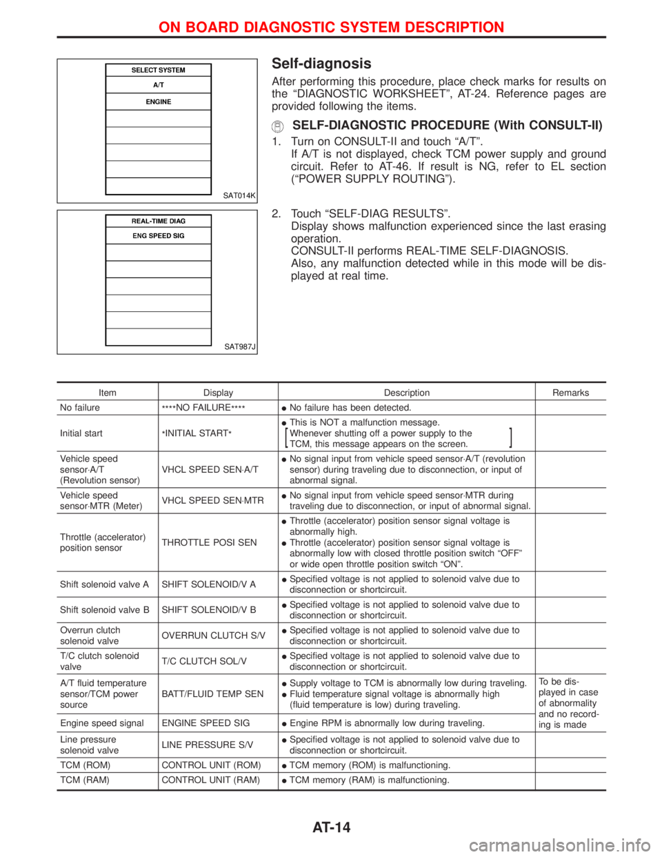
SELF-DIAGNOSTIC PROCEDURE (With CONSULT-II)
1. Turn on CONSULT-II and touch ªA/Tº.
If A/T is not displayed, check TCM power supply and ground
circuit. Refer to AT-46. If result is NG, refer to EL section
(ªPOWER SUPPLY ROUTINGº).
2. Touch ªSELF-DIAG RESULTSº.
Display shows malfunction experienced since the last erasing
operation.
CONSULT-II performs REAL-TIME SELF-DIAGNOSIS.
Also, any malfunction detected while in this mode will be dis-
played at real time.
Item Display Description Remarks
No failure
****NO FAILURE
****INo failure has been detected.
Initial start
*INITIAL START
*IThis is NOT a malfunction message.
Whenever shutting off a power supply to the
TCM, this message appears on the screen.
[]
Vehicle speed
sensor×A/T
(Revolution sensor)VHCL SPEED SEN×A/TINo signal input from vehicle speed sensor×A/T (revolution
sensor) during traveling due to disconnection, or input of
abnormal signal.
Vehicle speed
sensor×MTR (Meter)VHCL SPEED SEN×MTRINo signal input from vehicle speed sensor×MTR during
traveling due to disconnection, or input of abnormal signal.
Throttle (accelerator)
position sensorTHROTTLE POSI SENIThrottle (accelerator) position sensor signal voltage is
abnormally high.
IThrottle (accelerator) position sensor signal voltage is
abnormally low with closed throttle position switch ªOFFº
or wide open throttle position switch ªONº.
Shift solenoid valve A SHIFT SOLENOID/V AISpecified voltage is not applied to solenoid valve due to
disconnection or shortcircuit.
Shift solenoid valve B SHIFT SOLENOID/V BISpecified voltage is not applied to solenoid valve due to
disconnection or shortcircuit.
Overrun clutch
solenoid valveOVERRUN CLUTCH S/VISpecified voltage is not applied to solenoid valve due to
disconnection or shortcircuit.
T/C clutch solenoid
valveT/C CLUTCH SOL/VISpecified voltage is not applied to solenoid valve due to
disconnection or shortcircuit.
A/T fluid temperature
sensor/TCM power
sourceBATT/FLUID TEMP SENISupply voltage to TCM is abnormally low during traveling.
IFluid temperature signal voltage is abnormally high
(fluid temperature is low) during traveling.To be dis-
played in case
of abnormality
and no record-
ing is made Engine speed signal ENGINE SPEED SIGIEngine RPM is abnormally low during traveling.
Line pressure
solenoid valveLINE PRESSURE S/VISpecified voltage is not applied to solenoid valve due to
disconnection or shortcircuit.
TCM (ROM) CONTROL UNIT (ROM)ITCM memory (ROM) is malfunctioning.
TCM (RAM) CONTROL UNIT (RAM)ITCM memory (RAM) is malfunctioning.
SAT014K
SAT987J
ON BOARD DIAGNOSTIC SYSTEM DESCRIPTION
AT-14
Page 22 of 1767
Diagnosis by CONSULT-II
NOTICE
1. The CONSULT-II electrically displays shift timing and lock-up timing (that is, operation timing of each
solenoid).
Check for time difference between actual shift timing and the CONSULT-II display. If the difference is
noticeable, mechanical parts (except solenoids, sensors, etc.) may be malfunctioning. Check mechanical
parts using applicable diagnostic procedures.
2. Shift schedule (which implies gear position) displayed on CONSULT-II and that indicated in Service Manual
may differ slightly. This occurs because of the following reasons:
IActual shift schedule has more or less tolerance or allowance,
IShift schedule indicated in Service Manual refers to the point where shifts start. Gear position displayed
on CONSULT-II indicates the point where shifts are completed.
3. Shift solenoid valve ªAº or ªBº is displayed on CONSULT-II at the start of shifting. Gear position is displayed
upon completion of shifting (which is computed by TCM).
4. Additional CONSULT-II information can be found in the Operation Manual supplied with the CONSULT-II
unit.
SELF-DIAGNOSTIC RESULT TEST MODE
Refer to AT-14.
DATA MONITOR DIAGNOSTIC TEST MODE
Item DisplayMonitor item
Description Remarks ECU
input
signalsMain
signals
Vehicle speed sensor 1
(A/T)
(Revolution sensor)VHCL/S SE×A/T
[km/h] or [mph]
XÐIVehicle speed computed from signal
of revolution sensor is displayed.When racing engine in ªNº or ªPº posi-
tion with vehicle stationary, CON-
SULT-II data may not indicate
0 km/h (0 MPH).
Vehicle speed sensor 2
(Meter)VHCL/S SE×MTR
[km/h] or [mph]
XÐIVehicle speed computed from signal
of vehicle speed sensor is dis-
played.Vehicle speed display may not be
accurate under approx. 10 km/h
(6 MPH). It may not indicate 0 km/h (0
MPH) when vehicle is stationary.
Throttle (accelerator)
position sensorTHRTL POS SEN
[V]XÐIThrottle (accelerator) position sen-
sor signal voltage is displayed.
A/T fluid temperature
sensorFLUID TEMP SE
[V]
XÐIA/T fluid temperature sensor signal
voltage is displayed.
ISignal voltage lowers as fluid tem-
perature rises.
Battery voltage BATTERY VOLT
[V]XÐISource voltage of TCM is displayed.
Engine speed ENGINE SPEED
[rpm]
XXIEngine speed, computed from
engine speed signal, is displayed.Engine speed display may not be
accurate under approx. 800 rpm. It
may not indicate 0 rpm even when
engine is not running.
Overdrive control switch OVERDRIVE SW
[ON/OFF]XÐION/OFF state computed from signal
of overdrive control SW is displayed.
P/N position switch P/N POSI SW
[ON/OFF]XÐION/OFF state computed from signal
of P/N position SW is displayed.
R position switch R POSITION SW
[ON/OFF]XÐION/OFF state computed from signal
of R position SW is displayed.
D position switch D POSITION SW
[ON/OFF]XÐION/OFF state computed from signal
of D position SW is displayed.
2 position switch 2 POSITION SW
[ON/OFF]XÐION/OFF status, computed from sig-
nal of 2 position SW, is displayed.
1 position switch 1 POSITION SW
[ON/OFF]XÐION/OFF status, computed from sig-
nal of 1 position SW, is displayed.
ASCD-cruise signal ASCD×CRUISE
[ON/OFF]
XÐIStatus of ASCD cruise signal is dis-
played.
ON ... Cruising state
OFF ... Normal running stateIThis is displayed even when no
ASCD is mounted.
ON BOARD DIAGNOSTIC SYSTEM DESCRIPTION
AT-20
Page 125 of 1767
Disassembly
1. Drain ATF through drain plug.
2. Remove torque converter by holding it firmly and turning while
pulling straight out.
3. Check torque converter one-way clutch.
a. Insert Tool into spline of one-way clutch inner race.
b. Hook bearing support unitized with one-way clutch outer race
with suitable wire.
c. Check that one-way clutch inner race rotates only clockwise
with Tool while holding bearing support with wire.
4. Remove park/neutral position switch from transmission case.
5. Remove oil pan.
IAlways place oil pan straight down so that foreign par-
ticles inside will not move.
6. Place transmission into Tool with the control valve facing up.
SAT018B
NAT226
YAT339
SAT754I
NAT227
DISASSEMBLY
AT-123
Page 131 of 1767
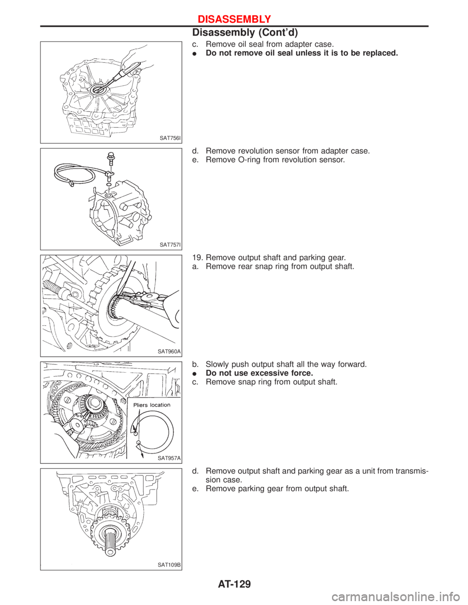
c. Remove oil seal from adapter case.
IDo not remove oil seal unless it is to be replaced.
d. Remove revolution sensor from adapter case.
e. Remove O-ring from revolution sensor.
19. Remove output shaft and parking gear.
a. Remove rear snap ring from output shaft.
b. Slowly push output shaft all the way forward.
IDo not use excessive force.
c. Remove snap ring from output shaft.
d. Remove output shaft and parking gear as a unit from transmis-
sion case.
e. Remove parking gear from output shaft.
SAT756I
SAT757I
SAT960A
SAT957A
SAT109B
DISASSEMBLY
Disassembly (Cont'd)
AT-129
Page 141 of 1767
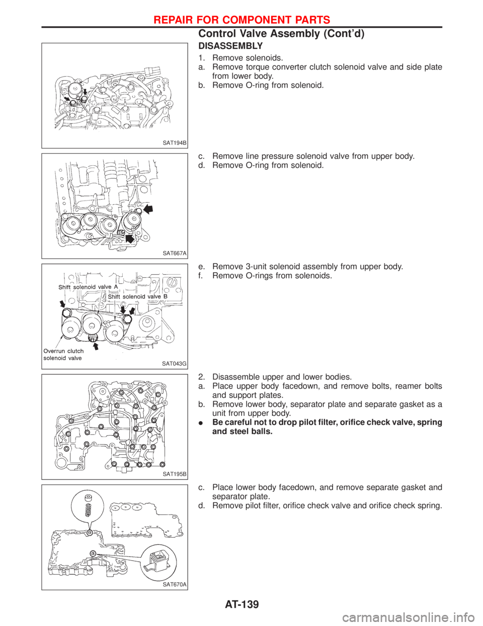
DISASSEMBLY
1. Remove solenoids.
a. Remove torque converter clutch solenoid valve and side plate
from lower body.
b. Remove O-ring from solenoid.
c. Remove line pressure solenoid valve from upper body.
d. Remove O-ring from solenoid.
e. Remove 3-unit solenoid assembly from upper body.
f. Remove O-rings from solenoids.
2. Disassemble upper and lower bodies.
a. Place upper body facedown, and remove bolts, reamer bolts
and support plates.
b. Remove lower body, separator plate and separate gasket as a
unit from upper body.
IBe careful not to drop pilot filter, orifice check valve, spring
and steel balls.
c. Place lower body facedown, and remove separate gasket and
separator plate.
d. Remove pilot filter, orifice check valve and orifice check spring.
SAT194B
SAT667A
SAT043G
SAT195B
SAT670A
REPAIR FOR COMPONENT PARTS
Control Valve Assembly (Cont'd)
AT-139
Page 143 of 1767
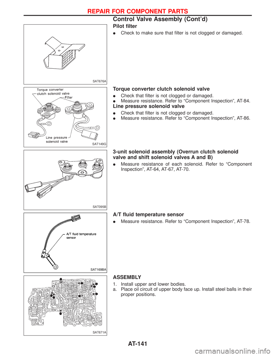
Pilot filter
ICheck to make sure that filter is not clogged or damaged.
Torque converter clutch solenoid valve
ICheck that filter is not clogged or damaged.
IMeasure resistance. Refer to ªComponent Inspectionº, AT-84.
Line pressure solenoid valve
ICheck that filter is not clogged or damaged.
IMeasure resistance. Refer to ªComponent Inspectionº, AT-86.
3-unit solenoid assembly (Overrun clutch solenoid
valve and shift solenoid valves A and B)
IMeasure resistance of each solenoid. Refer to ªComponent
Inspectionº, AT-64, AT-67, AT-70.
A/T fluid temperature sensor
IMeasure resistance. Refer to ªComponent Inspectionº, AT-78.
ASSEMBLY
1. Install upper and lower bodies.
a. Place oil circuit of upper body face up. Install steel balls in their
proper positions.
SAT676A
SAT149G
SAT095B
SAT169BA
SAT671A
REPAIR FOR COMPONENT PARTS
Control Valve Assembly (Cont'd)
AT-141
Page 145 of 1767
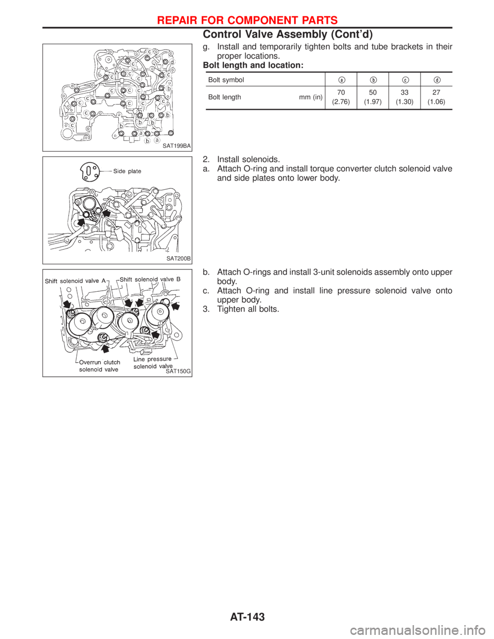
g. Install and temporarily tighten bolts and tube brackets in their
proper locations.
Bolt length and location:
Bolt symbolqaqbqcqd
Bolt length mm (in)70
(2.76)50
(1.97)33
(1.30)27
(1.06)
2. Install solenoids.
a. Attach O-ring and install torque converter clutch solenoid valve
and side plates onto lower body.
b. Attach O-rings and install 3-unit solenoids assembly onto upper
body.
c. Attach O-ring and install line pressure solenoid valve onto
upper body.
3. Tighten all bolts.
SAT199BA
SAT200B
SAT150G
REPAIR FOR COMPONENT PARTS
Control Valve Assembly (Cont'd)
AT-143
Page 171 of 1767
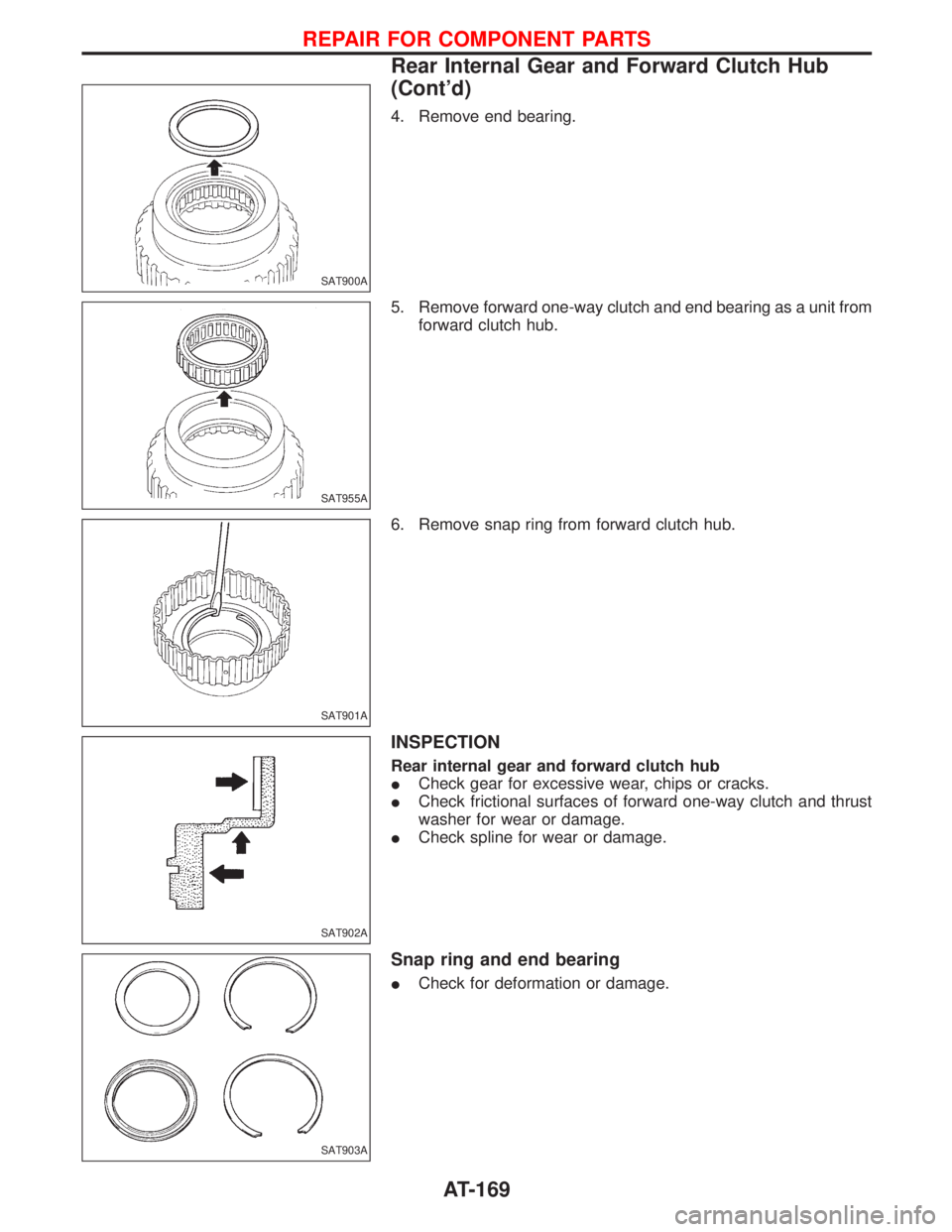
4. Remove end bearing.
5. Remove forward one-way clutch and end bearing as a unit from
forward clutch hub.
6. Remove snap ring from forward clutch hub.
INSPECTION
Rear internal gear and forward clutch hub
ICheck gear for excessive wear, chips or cracks.
ICheck frictional surfaces of forward one-way clutch and thrust
washer for wear or damage.
ICheck spline for wear or damage.
Snap ring and end bearing
ICheck for deformation or damage.
SAT900A
SAT955A
SAT901A
SAT902A
SAT903A
REPAIR FOR COMPONENT PARTS
Rear Internal Gear and Forward Clutch Hub
(Cont'd)
AT-169
Page 179 of 1767
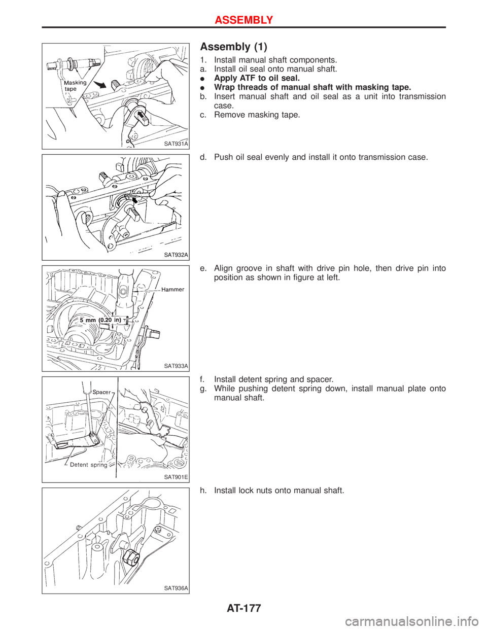
Assembly (1)
1. Install manual shaft components.
a. Install oil seal onto manual shaft.
IApply ATF to oil seal.
IWrap threads of manual shaft with masking tape.
b. Insert manual shaft and oil seal as a unit into transmission
case.
c. Remove masking tape.
d. Push oil seal evenly and install it onto transmission case.
e. Align groove in shaft with drive pin hole, then drive pin into
position as shown in figure at left.
f. Install detent spring and spacer.
g. While pushing detent spring down, install manual plate onto
manual shaft.
h. Install lock nuts onto manual shaft.
SAT931A
SAT932A
SAT933A
SAT901E
SAT936A
ASSEMBLY
AT-177