Location NISSAN TERRANO 2004 Service User Guide
[x] Cancel search | Manufacturer: NISSAN, Model Year: 2004, Model line: TERRANO, Model: NISSAN TERRANO 2004Pages: 1833, PDF Size: 53.42 MB
Page 289 of 1833
MEC990D
ENGINE AND EMISSION CONTROL OVERALL SYSTEMZD30DDTi
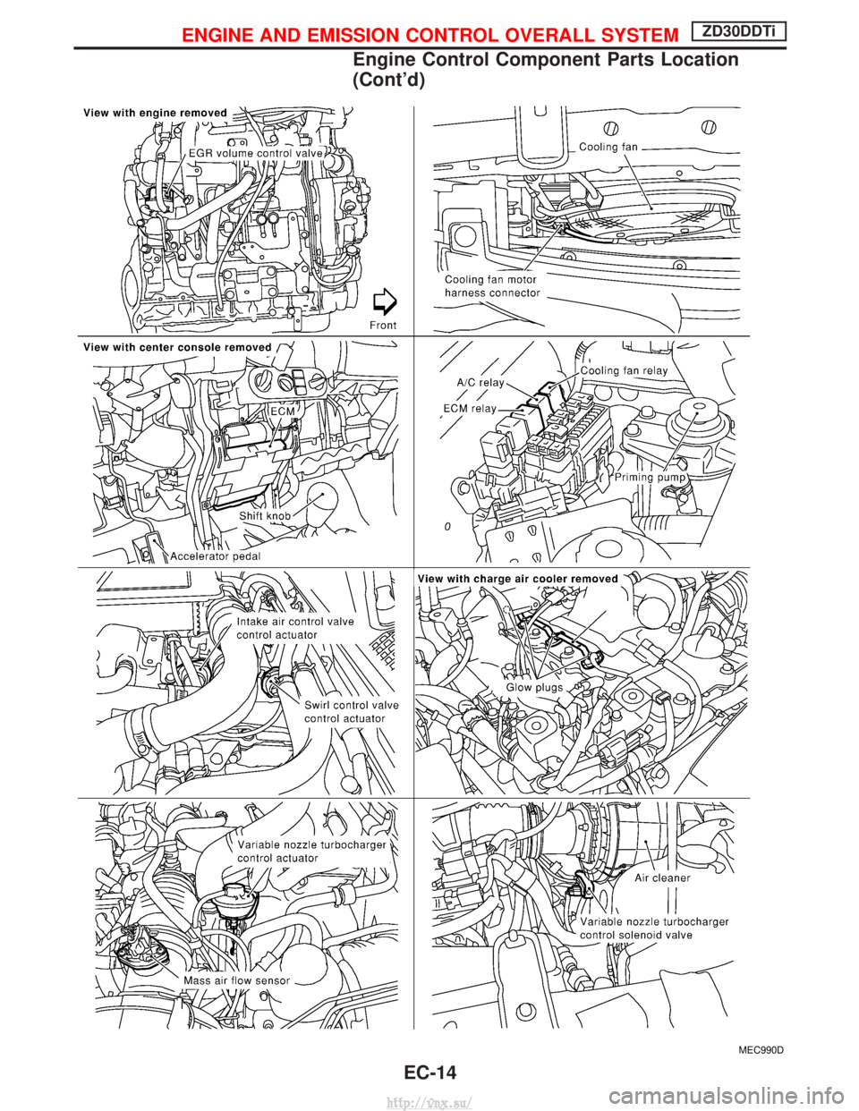
Engine Control Component Parts Location
(Cont'd)EC-14
http://vnx.su/
Page 290 of 1833
MEC029E
ENGINE AND EMISSION CONTROL OVERALL SYSTEMZD30DDTi
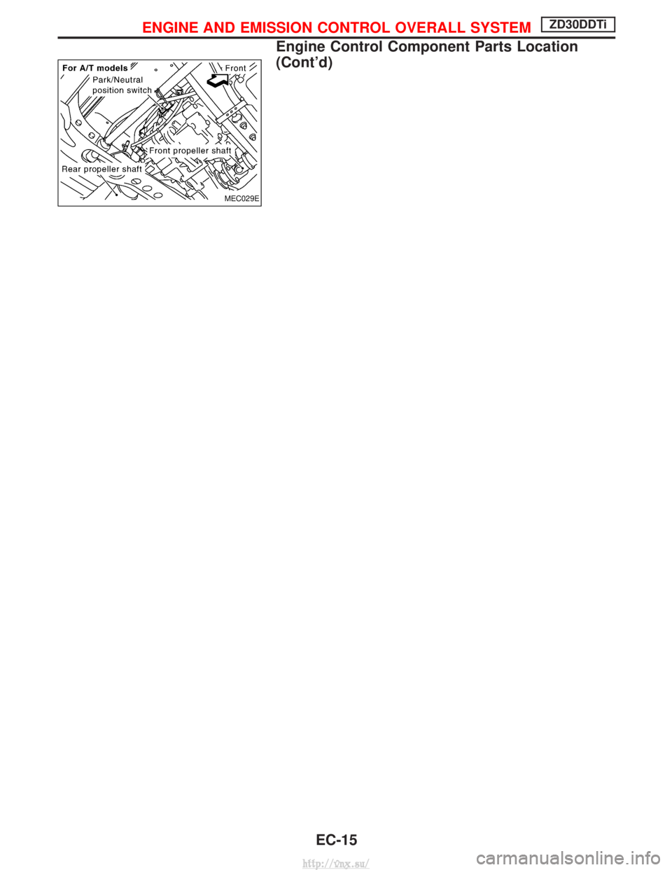
Engine Control Component Parts Location
(Cont'd)EC-15
http://vnx.su/
Page 299 of 1833
Injection Tube and Injection Nozzle
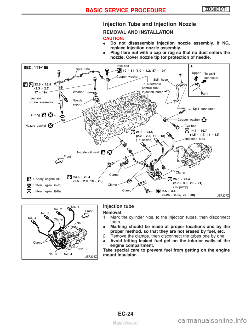
REMOVAL AND INSTALLATION
CAUTION:
IDo not disassemble injection nozzle assembly. If NG,
replace injection nozzle assembly.
I Plug flare nut with a cap or rag so that no dust enters the
nozzle. Cover nozzle tip for protection of needle.
Injection tube
Removal
1. Mark the cylinder Nos. to the injection tubes, then disconnect
them.
I Marking should be made at proper locations and by the
proper method, so that they are not erased by fuel, etc.
2. Remove the clamps, then disconnect the tubes one by one.
I Avoid letting leaked fuel get on the interior walls of the
engine compartment.
Take special care to prevent fuel from getting on the engine
mount insulator.
JEF237Z
JEF238Z
BASIC SERVICE PROCEDUREZD30DDTi
EC-24
http://vnx.su/
Page 519 of 1833
Description
SYSTEM DESCRIPTION
Sensor Input Signal to ECMECM
Function Actuator
Crankshaft position
sensor (TDC) Engine speed
Glow
control Glow lamp,
Glow relay "
Glow plugs
Engine coolant tem-
perature sensor Engine coolant tem-
perature
When engine coolant temperature is more than approximately 75ÉC
(167ÉF), the glow relay turns off, inactivating the quick-glow control
until coolant temperature drops below approximately 55ÉC (131ÉF).
When coolant temperature is lower than approximately 75ÉC
(167ÉF):
I
Ignition switch ON
After ignition switch has turned to ON, the glow relay turns ON
for a certain period of time in relation to engine coolant
temperature, allowing current to flow through glow plug.
I Cranking
The glow relay turns ON, allowing current to flow through glow
plug.
I Starting
After engine has started, current continues to flow through glow
plug (after-glow mode) for a certain period in relation to engine
coolant temperature.
When engine speed exceeds approximately 4,800 rpm, current
flow through glow plug is interrupted.
The glow indicator lamp turns ON for a certain period of time in
relation to engine coolant temperature at the time glow relay is
turned ON.
COMPONENT DESCRIPTION
Glow plug
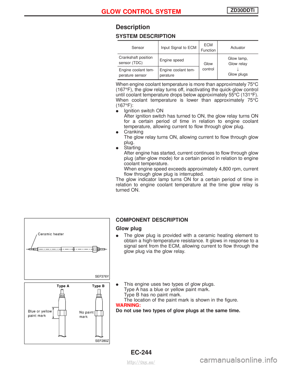
I The glow plug is provided with a ceramic heating element to
obtain a high-temperature resistance. It glows in response to a
signal sent from the ECM, allowing current to flow through the
glow plug via the glow relay.
I This engine uses two types of glow plugs.
Type A has a blue or yellow paint mark.
Type B has no paint mark.
The location of the paint mark is shown in the figure.
WARNING:
Do not use two types of glow plugs at the same time.
SEF376Y
SEF280Z
GLOW CONTROL SYSTEMZD30DDTi
EC-244
http://vnx.su/
Page 592 of 1833
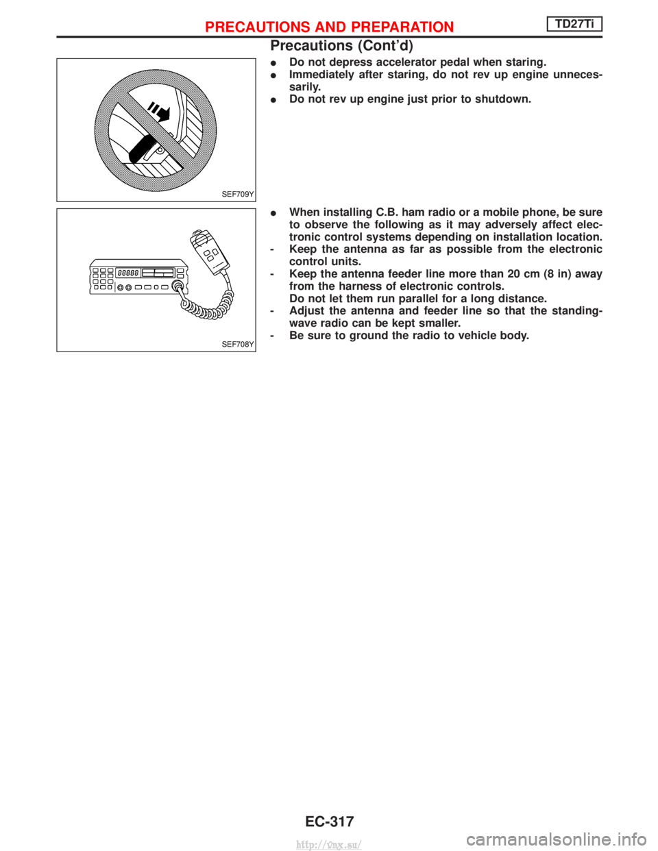
IDo not depress accelerator pedal when staring.
I Immediately after staring, do not rev up engine unneces-
sarily.
I Do not rev up engine just prior to shutdown.
I When installing C.B. ham radio or a mobile phone, be sure
to observe the following as it may adversely affect elec-
tronic control systems depending on installation location.
- Keep the antenna as far as possible from the electronic control units.
- Keep the antenna feeder line more than 20 cm (8 in) away from the harness of electronic controls.
Do not let them run parallel for a long distance.
- Adjust the antenna and feeder line so that the standing- wave radio can be kept smaller.
- Be sure to ground the radio to vehicle body.
SEF709Y
SEF708Y
PRECAUTIONS AND PREPARATIONTD27Ti
Precautions (Cont'd)
EC-317
http://vnx.su/
Page 598 of 1833
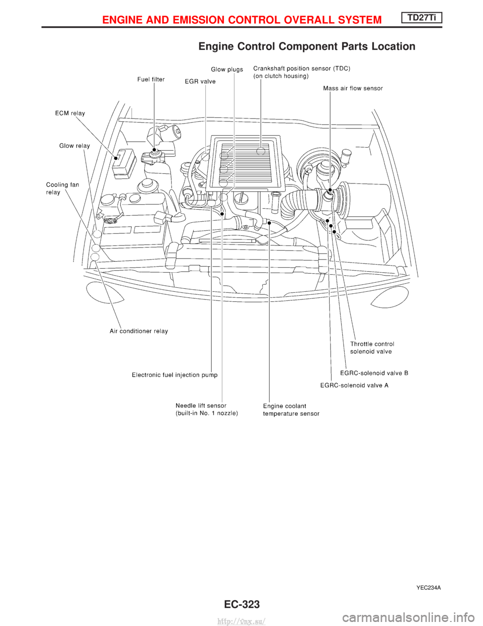
Engine Control Component Parts Location
YEC234A
ENGINE AND EMISSION CONTROL OVERALL SYSTEMTD27Ti
EC-323
http://vnx.su/
Page 599 of 1833
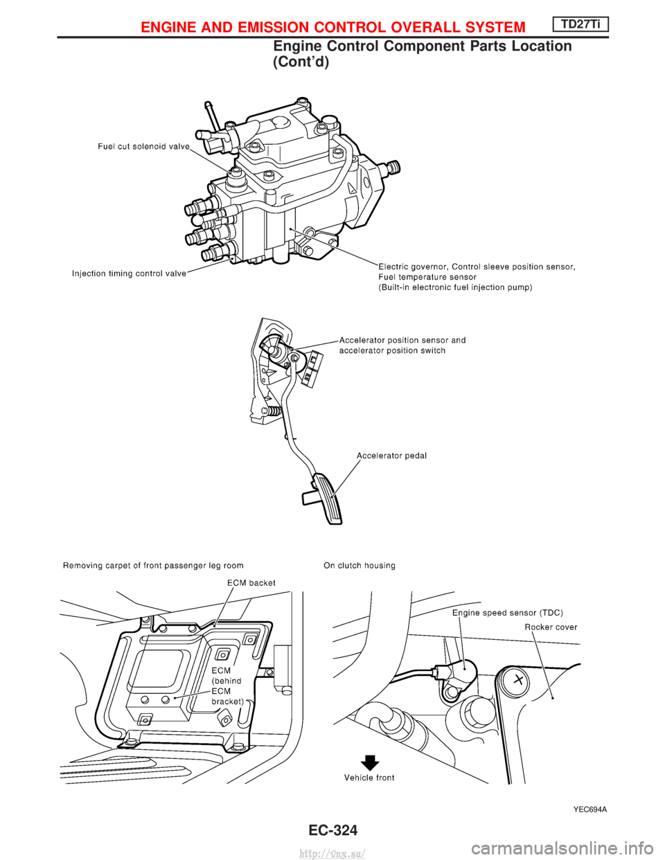
YEC694A
ENGINE AND EMISSION CONTROL OVERALL SYSTEMTD27Ti
Engine Control Component Parts Location
(Cont'd)EC-324
http://vnx.su/
Page 814 of 1833
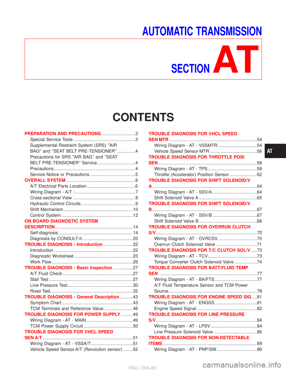
AUTOMATIC TRANSMISSIONSECTION
AT
CONTENTS
PREPARATION AND PRECAUTIONS ............................3
Special Service Tools ..................................................3
Supplemental Restraint System (SRS) ²AIR
BAG² and²SEAT BELT PRE-TENSIONER² ...............4
Precautions for SRS ²AIR BAG² and²SEAT
BELT PRE-TENSIONER² Service ...............................4
Precautions ..................................................................4
Service Notice or Precautions .....................................5
OVERALL SYSTEM ........................................................6
A/T Electrical Parts Location .......................................6
Wiring Diagram - A/T -.................................................7
Cross-sectional View ...................................................8
Hydraulic Control Circuits ............................................9
Shift Mechanism ........................................................10
Control System ..........................................................12
ON BOARD DIAGNOSTIC SYSTEM
DESCRIPTION ...............................................................14
Self-diagnosis ............................................................14
Diagnosis by CONSULT-II .........................................20
TROUBLE DIAGNOSIS - Introduction ........................22
Introduction ................................................................22
Diagnostic Worksheet ................................................23
Work Flow ..................................................................26
TROUBLE DIAGNOSIS - Basic Inspection ................27
A/T Fluid Check .........................................................27
Stall Test ....................................................................27
Line Pressure Test .....................................................30
Road Test...................................................................32
TROUBLE DIAGNOSIS - General Description ...........43
Symptom Chart ..........................................................43
TCM Terminals and Reference Value........................46
TROUBLE DIAGNOSIS FOR POWER SUPPLY ..........49
Wiring Diagram - AT - MAIN ......................................49
TCM Power Supply Circuit ........................................50
TROUBLE DIAGNOSIS FOR VHCL SPEED
SEN×A/T ........................................................................\
.51
Wiring Diagram - AT - VSSA/T ..................................51
Vehicle Speed Sensor×A/T (Revolution sensor) ........52 TROUBLE DIAGNOSIS FOR VHCL SPEED
SEN×MTR
.......................................................................54
Wiring Diagram - AT - VSSMTR ................................54
Vehicle Speed Sensor×MTR ......................................56
TROUBLE DIAGNOSIS FOR THROTTLE POSI
SEN ........................................................................\
........58
Wiring Diagram - AT - TPS ........................................58
Throttle (Accelerator) Position Sensor ......................62
TROUBLE DIAGNOSIS FOR SHIFT SOLENOID/V
A ........................................................................\
.............64
Wiring Diagram - AT - SSV/A ....................................64
Shift Solenoid Valve A ...............................................65
TROUBLE DIAGNOSIS FOR SHIFT SOLENOID/V
B ........................................................................\
.............67
Wiring Diagram - AT - SSV/B ....................................67
Shift Solenoid Valve B ...............................................68
TROUBLE DIAGNOSIS FOR OVERRUN CLUTCH
S/V ........................................................................\
..........70
Wiring Diagram - AT - OVRCSV................................70
Overrun Clutch Solenoid Valve .................................71
TROUBLE DIAGNOSIS FOR T/C CLUTCH SOL/V .....73
Wiring Diagram - AT - TCV........................................73
Torque Converter Clutch Solenoid Valve ..................74
TROUBLE DIAGNOSIS FOR BATT/FLUID TEMP
SEN ........................................................................\
........77
Wiring Diagram - AT - BA/FTS ..................................77
A/T Fluid Temperature Sensor and TCM Power
Source........................................................................\
78
TROUBLE DIAGNOSIS FOR ENGINE SPEED SIG ....81
Wiring Diagram - AT - ENGSS ..................................81
Engine Speed Signal .................................................82
TROUBLE DIAGNOSIS FOR LINE PRESSURE
S/V ........................................................................\
..........84
Wiring Diagram - AT - LPSV......................................84
Line Pressure Solenoid Valve ...................................86
TROUBLE DIAGNOSIS FOR NON-DETECTABLE
ITEMS........................................................................\
.....89 Wiring Diagram - AT - PNP/SW.................................89
http://vnx.su/
Page 815 of 1833
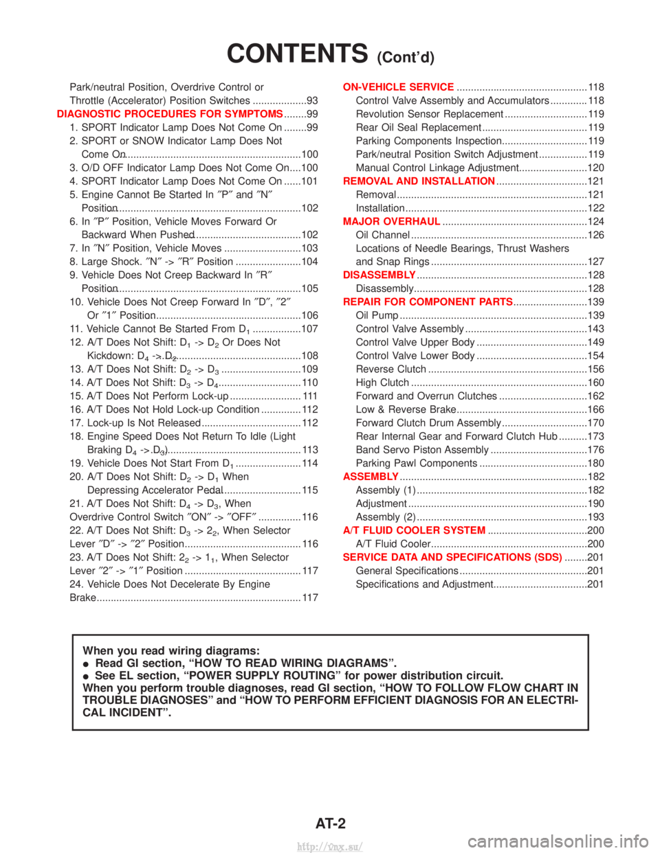
Park/neutral Position, Overdrive Control or
Throttle (Accelerator) Position Switches ...................93
DIAGNOSTIC PROCEDURES FOR SYMPTOMS ........99
1. SPORT Indicator Lamp Does Not Come On ........99
2. SPORT or SNOW Indicator Lamp Does Not Come On.................................................................100
3. O/D OFF Indicator Lamp Does Not Come On....100
4. SPORT Indicator Lamp Does Not Come On ......101
5. Engine Cannot Be Started In ²P² and ²N²
Position....................................................................102
6. In ²P² Position, Vehicle Moves Forward Or
Backward When Pushed.........................................102
7. In ²N² Position, Vehicle Moves ...........................103
8. Large Shock. ²N² ->²R² Position .......................104
9. Vehicle Does Not Creep Backward In ²R²
Position....................................................................105
10. Vehicle Does Not Creep Forward In ²D² ,²2²
Or ²1² Position.........................................................106
11. Vehicle Cannot Be Started From D
1.................107
12. A/T Does Not Shift: D
1-> D2Or Does Not
Kickdown: D
4-> D2..................................................108
13. A/T Does Not Shift: D
2-> D3............................109
14. A/T Does Not Shift: D
3-> D4............................. 110
15. A/T Does Not Perform Lock-up ......................... 111
16. A/T Does Not Hold Lock-up Condition .............. 112
17. Lock-up Is Not Released ................................... 112
18. Engine Speed Does Not Return To Idle (Light Braking D
4-> D3)..................................................... 113
19. Vehicle Does Not Start From D
1....................... 114
20. A/T Does Not Shift: D
2-> D1When
Depressing Accelerator Pedal................................. 115
21. A/T Does Not Shift: D
4-> D3, When
Overdrive Control Switch ²ON² ->²OFF² ............... 116
22. A/T Does Not Shift: D
3-> 22, When Selector
Lever ²D² ->²2² Position......................................... 116
23. A/T Does Not Shift: 2
2-> 11, When Selector
Lever ²2² ->²1² Position ......................................... 117
24. Vehicle Does Not Decelerate By Engine
Brake........................................................................\
117 ON-VEHICLE SERVICE
.............................................. 118
Control Valve Assembly and Accumulators ............. 118
Revolution Sensor Replacement ............................. 119
Rear Oil Seal Replacement ..................................... 119
Parking Components Inspection.............................. 119
Park/neutral Position Switch Adjustment ................. 119
Manual Control Linkage Adjustment........................120
REMOVAL AND INSTALLATION ................................121
Removal ...................................................................121
Installation ................................................................122
MAJOR OVERHAUL ...................................................124
Oil Channel ..............................................................126
Locations of Needle Bearings, Thrust Washers
and Snap Rings .......................................................127
DISASSEMBLY ............................................................128
Disassembly.............................................................128
REPAIR FOR COMPONENT PARTS ..........................139
Oil Pump ..................................................................139
Control Valve Assembly ...........................................143
Control Valve Upper Body .......................................149
Control Valve Lower Body .......................................154
Reverse Clutch ........................................................156
High Clutch ..............................................................160
Forward and Overrun Clutches ...............................162
Low & Reverse Brake..............................................166
Forward Clutch Drum Assembly ..............................170
Rear Internal Gear and Forward Clutch Hub ..........173
Band Servo Piston Assembly ..................................176
Parking Pawl Components ......................................180
ASSEMBLY ..................................................................182
Assembly (1) ............................................................182
Adjustment ...............................................................190
Assembly (2) ............................................................193
A/T FLUID COOLER SYSTEM ...................................200
A/T Fluid Cooler.......................................................200
SERVICE DATA AND SPECIFICATIONS (SDS) ........201
General Specifications .............................................201
Specifications and Adjustment.................................201
When you read wiring diagrams:
I Read GI section, ªHOW TO READ WIRING DIAGRAMSº.
I See EL section, ªPOWER SUPPLY ROUTINGº for power distribution circuit.
When you perform trouble diagnoses, read GI section, ªHOW TO FOLLOW FLOW CHART IN
TROUBLE DIAGNOSESº and ªHOW TO PERFORM EFFICIENT DIAGNOSIS FOR AN ELECTRI-
CAL INCIDENTº.
CONTENTS(Cont'd)
AT- 2
http://vnx.su/
Page 819 of 1833
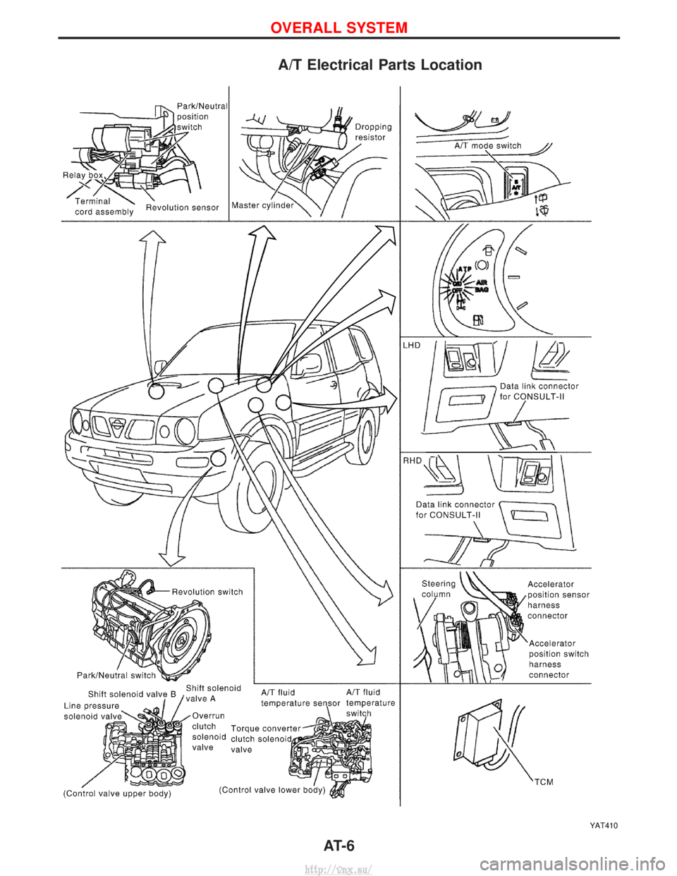
A/T Electrical Parts Location
YAT410
OVERALL SYSTEM
AT- 6
http://vnx.su/