low oil pressure NISSAN TERRANO 2004 Service Owner's Manual
[x] Cancel search | Manufacturer: NISSAN, Model Year: 2004, Model line: TERRANO, Model: NISSAN TERRANO 2004Pages: 1833, PDF Size: 53.42 MB
Page 579 of 1833

12 CHECK COMBINATION METER
Check combination meter continuity between the following terminals. Refer to Wiring Diagram.
MTBL1798
YEC702A
OK or NG
OK EGO TO 13.
NG ERepair or replace combination meter. Refer to EL section.
13 CHECK INTERMITTENT INCIDENT
Refer to ªTROUBLE DIAGNOSIS FOR INTERMITTENT INCIDENTº, EC-78.
OK EReplace engine oil pressure switch-1.
NG ERepair harness or connectors.
14 OVERALL FUNCTION CHECK-IV
1. Turn ignition switch ªOFFº.
2. Disconnect engine oil pressure switch-1 harness connector.
3. Turn ignition switch ªONº and wait at least 3 seconds.
4. Start engine and let it idle.
5. Check oil pressure warning lamp illumination.
Oil pressure warning lamp should go off.
OK or NG
OK EReplace engine oil pressure switch-1.
NG EGO TO 15.
ENGINE OIL PRESSURE SWITCHZD30DDTi
Diagnostic Procedure (Cont'd)
EC-304
http://vnx.su/
Page 580 of 1833
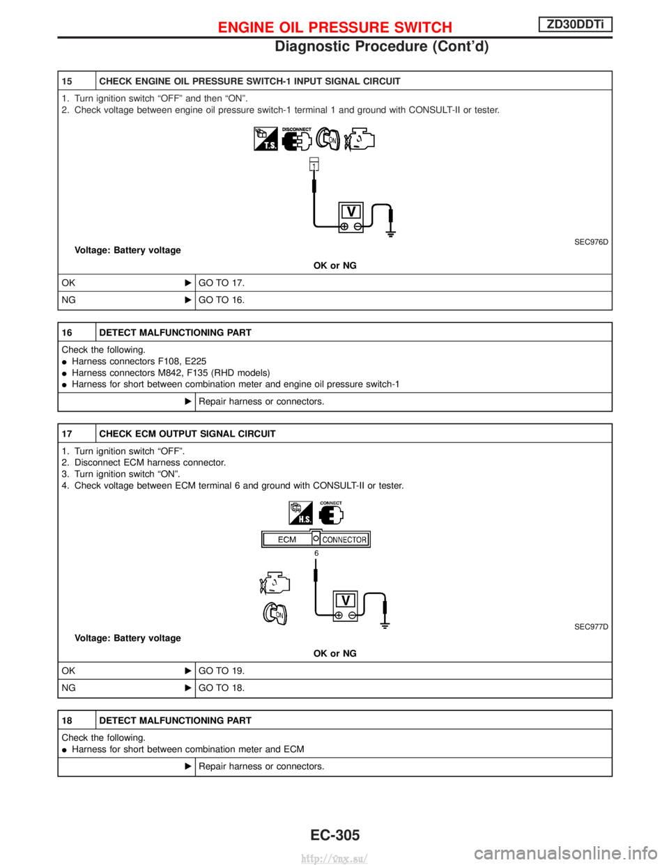
15 CHECK ENGINE OIL PRESSURE SWITCH-1 INPUT SIGNAL CIRCUIT
1. Turn ignition switch ªOFFº and then ªONº.
2. Check voltage between engine oil pressure switch-1 terminal 1 and ground with CONSULT-II or tester.
SEC976DVoltage: Battery voltageOK or NG
OK EGO TO 17.
NG EGO TO 16.
16 DETECT MALFUNCTIONING PART
Check the following.
IHarness connectors F108, E225
I Harness connectors M842, F135 (RHD models)
I Harness for short between combination meter and engine oil pressure switch-1
ERepair harness or connectors.
17 CHECK ECM OUTPUT SIGNAL CIRCUIT
1. Turn ignition switch ªOFFº.
2. Disconnect ECM harness connector.
3. Turn ignition switch ªONº.
4. Check voltage between ECM terminal 6 and ground with CONSULT-II or tester.
SEC977D
Voltage: Battery voltage
OK or NG
OK EGO TO 19.
NG EGO TO 18.
18 DETECT MALFUNCTIONING PART
Check the following.
IHarness for short between combination meter and ECM
ERepair harness or connectors.
ENGINE OIL PRESSURE SWITCHZD30DDTi
Diagnostic Procedure (Cont'd)
EC-305
http://vnx.su/
Page 581 of 1833
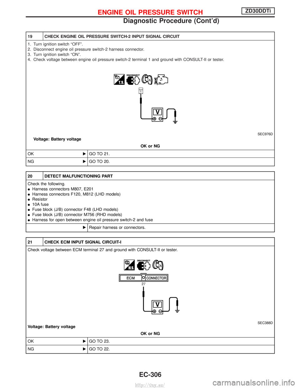
19 CHECK ENGINE OIL PRESSURE SWITCH-2 INPUT SIGNAL CIRCUIT
1. Turn ignition switch ªOFFº.
2. Disconnect engine oil pressure switch-2 harness connector.
3. Turn ignition switch ªONº.
4. Check voltage between engine oil pressure switch-2 terminal 1 and ground with CONSULT-II or tester.
SEC976D
Voltage: Battery voltageOK or NG
OK EGO TO 21.
NG EGO TO 20.
20 DETECT MALFUNCTIONING PART
Check the following.
IHarness connectors M807, E201
I Harness connectors F120, M812 (LHD models)
I Resistor
I 10A fuse
I Fuse block (J/B) connector F48 (LHD models)
I Fuse block (J/B) connector M756 (RHD models)
I Harness for open between engine oil pressure switch-2 and fuse
ERepair harness or connectors.
21 CHECK ECM INPUT SIGNAL CIRCUIT-I
Check voltage between ECM terminal 27 and ground with CONSULT-II or tester.
SEC388DVoltage: Battery voltage
OK or NG
OK EGO TO 23.
NG EGO TO 22.
ENGINE OIL PRESSURE SWITCHZD30DDTi
Diagnostic Procedure (Cont'd)
EC-306
http://vnx.su/
Page 582 of 1833
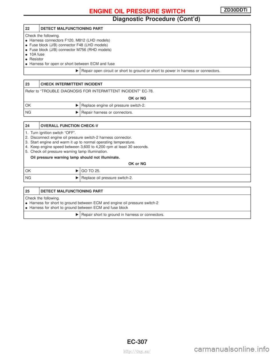
22 DETECT MALFUNCTIONING PART
Check the following.
IHarness connectors F120, M812 (LHD models)
I Fuse block (J/B) connector F48 (LHD models)
I Fuse block (J/B) connector M756 (RHD models)
I 10A fuse
I Resistor
I Harness for open or short between ECM and fuse
ERepair open circuit or short to ground or short to power in harness or connectors.
23 CHECK INTERMITTENT INCIDENT
Refer to ªTROUBLE DIAGNOSIS FOR INTERMITTENT INCIDENTº EC-78.
OK or NG
OK EReplace engine oil pressure switch-2.
NG ERepair harness or connectors.
24 OVERALL FUNCTION CHECK-V
1. Turn ignition switch ªOFFº.
2. Disconnect engine oil pressure switch-2 harness connector.
3. Start engine and warm it up to normal operating temperature.
4. Keep engine speed between 3,600 to 4,200 rpm at least 30 seconds.
5. Check oil pressure warning lamp illumination.
Oil pressure warning lamp should not illuminate.
OK or NG
OK EGO TO 25.
NG EReplace oil pressure switch-2.
25 DETECT MALFUNCTIONING PART
Check the following.
IHarness for short to ground between ECM and engine oil pressure switch-2
I Harness for short to ground between ECM and fuse block
ERepair short to ground in harness or connectors.
ENGINE OIL PRESSURE SWITCHZD30DDTi
Diagnostic Procedure (Cont'd)
EC-307
http://vnx.su/
Page 638 of 1833
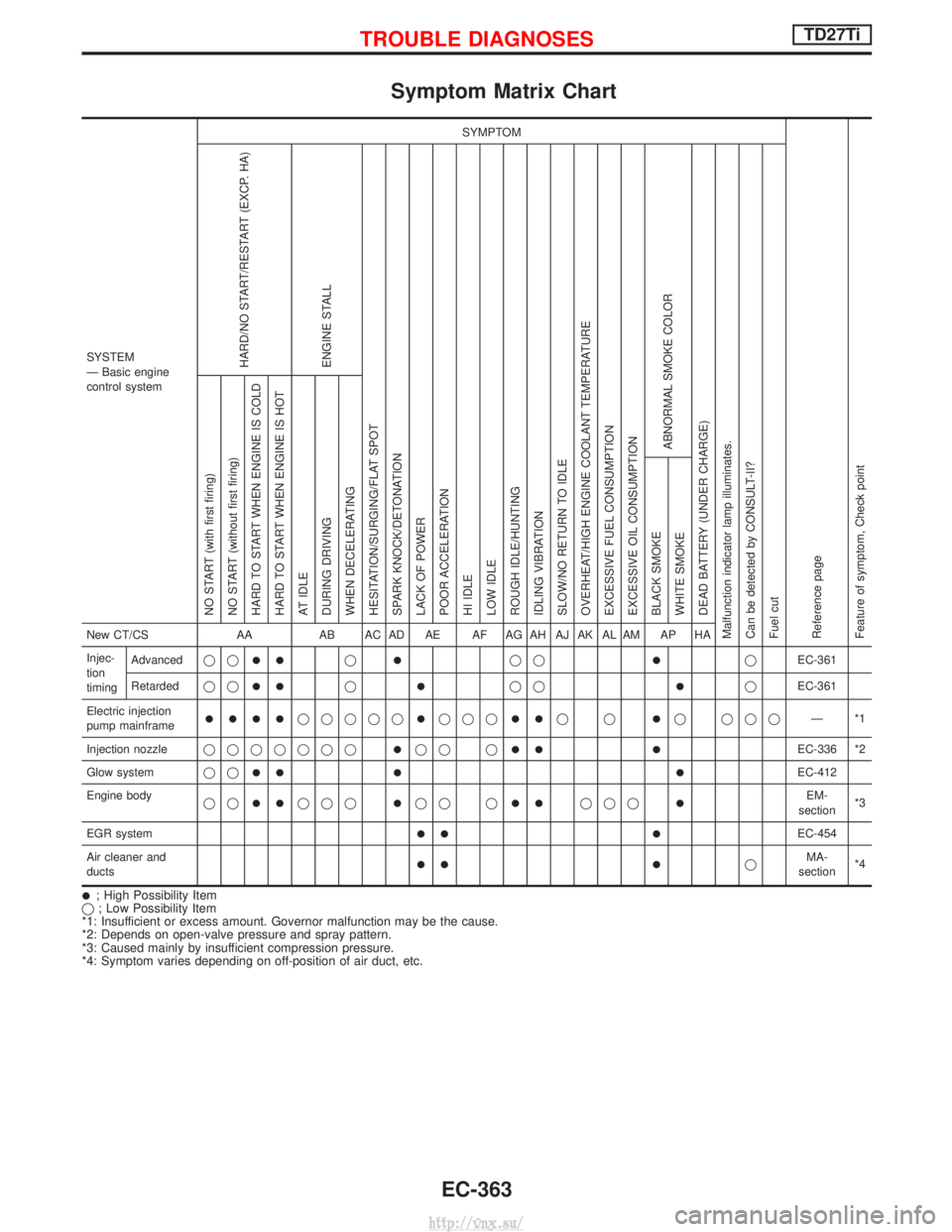
Symptom Matrix Chart
SYSTEM
Ð Basic engine
control systemSYMPTOM
Reference page
Feature of symptom, Check pointHARD/NO START/RESTART (EXCP. HA)
ENGINE STALL
HESITATION/SURGING/FLAT SPOT
SPARK KNOCK/DETONATION
LACK OF POWER
POOR ACCELERATION
HI IDLE
LOW IDLE
ROUGH IDLE/HUNTING
IDLING VIBRATION
SLOW/NO RETURN TO IDLE
OVERHEAT/HIGH ENGINE COOLANT TEMPERATURE
EXCESSIVE FUEL CONSUMPTION
EXCESSIVE OIL CONSUMPTION ABNORMAL SMOKE COLOR
DEAD BATTERY (UNDER CHARGE)
Malfunction indicator lamp illuminates.
Can be detected by CONSULT-II?
Fuel cut NO START (with first firing)
NO START (without first firing)
HARD TO START WHEN ENGINE IS COLD
HARD TO START WHEN ENGINE IS HOT
AT IDLE
DURING DRIVING
WHEN DECELERATING
BLACK SMOKE
WHITE SMOKENew CT/CS
AAAB AC AD AE AF AG AH AJ AK AL AM AP HA
Injec-
tion
timing Advanced
qq
IIqIqqIqEC-361
Retarded qq
IIqIqqIqEC-361
Electric injection
pump mainframe
IIIIqqqqqIqqqIIqqIq qqq Ð*1
Injection nozzle qqqqqqq
Iqq qIIIEC-336 *2
Glow system qq
III IEC-412
Engine body qq
IIqqqIqq qIIqqqIEM-
section *3
EGR system
II IEC-454
Air cleaner and
ducts
II IqMA-
section *4
I; High Possibility Item
q ; Low Possibility Item
*1: Insufficient or excess amount. Governor malfunction may be the cause.
*2: Depends on open-valve pressure and spray pattern.
*3: Caused mainly by insufficient compression pressure.
*4: Symptom varies depending on off-position of air duct, etc.
TROUBLE DIAGNOSESTD27Ti
EC-363
http://vnx.su/
Page 645 of 1833
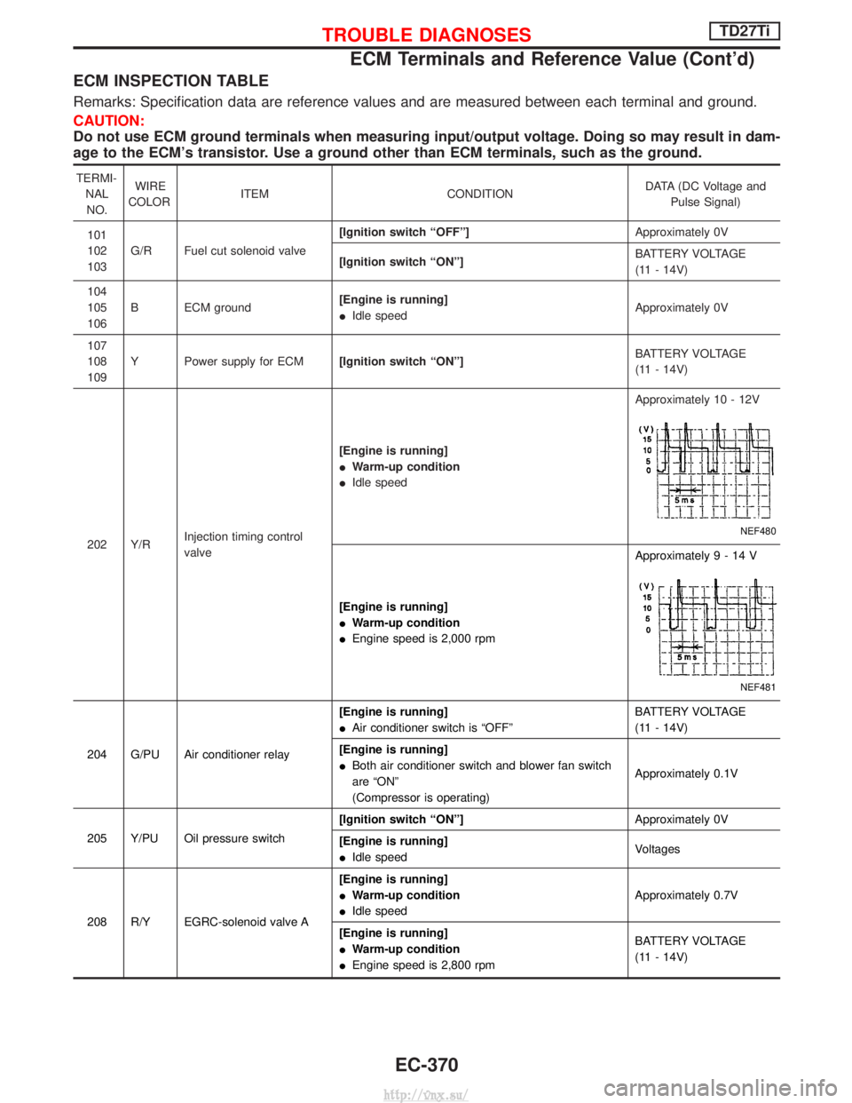
ECM INSPECTION TABLE
Remarks: Specification data are reference values and are measured between each terminal and ground.
CAUTION:
Do not use ECM ground terminals when measuring input/output voltage. Doing so may result in dam-
age to the ECM's transistor. Use a ground other than ECM terminals, such as the ground.
TERMI-NALNO. WIRE
COLOR ITEM CONDITION DATA (DC Voltage and
Pulse Signal)
101
102
103 G/R Fuel cut solenoid valve [Ignition switch ªOFFº]
Approximately 0V
[Ignition switch ªONº] BATTERY VOLTAGE
(11 - 14V)
104
105
106 B ECM ground
[Engine is running]
I
Idle speed Approximately 0V
107
108
109 Y Power supply for ECM
[Ignition switch ªONº] BATTERY VOLTAGE
(11 - 14V)
202 Y/R Injection timing control
valve [Engine is running]
I
Warm-up condition
I Idle speed Approximately 10 - 12V
NEF480
[Engine is running]
I
Warm-up condition
I Engine speed is 2,000 rpm Approximately9-14V
NEF481
204 G/PU Air conditioner relay
[Engine is running]
I
Air conditioner switch is ªOFFº BATTERY VOLTAGE
(11 - 14V)
[Engine is running]
I Both air conditioner switch and blower fan switch
are ªONº
(Compressor is operating) Approximately 0.1V
205 Y/PU Oil pressure switch [Ignition switch ªONº]
Approximately 0V
[Engine is running]
I Idle speed Voltages
208 R/Y EGRC-solenoid valve A [Engine is running]
I
Warm-up condition
I Idle speed Approximately 0.7V
[Engine is running]
I Warm-up condition
I Engine speed is 2,800 rpm BATTERY VOLTAGE
(11 - 14V)
TROUBLE DIAGNOSESTD27Ti
ECM Terminals and Reference Value (Cont'd)
EC-370
http://vnx.su/
Page 824 of 1833
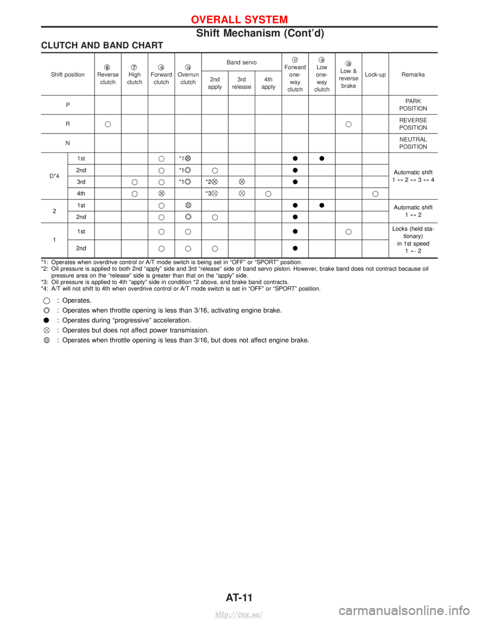
CLUTCH AND BAND CHART
Shift positionq6Reverse
clutch q7High
clutch q16Forward
clutch q18Overrun
clutch Band servo
q
17Forward
one-way
clutch q19Low
one- way
clutch q20Low &
reverse brake Lock-up Remarks
2nd
apply 3rd
release 4th
apply
P PARK
POSITION
R q qREVERSE
POSITION
N NEUTRAL
POSITION
D*4 1st
q*1
vv
Automatic shift
1 ) 2) 3) 4
2nd
q*1
q v
3rd qq*1
*2v
4th q
*3qq
2 1st
q
vv
Automatic shift
1) 2
2nd q
qv
1 1st
qq vqLocks (held sta-
tionary)
in 1st speed 1+ 2
2nd
qqq v
*1: Operates when overdrive control or A/T mode switch is being set in ªOFFº or ªSPORTº position.
*2: Oil pressure is applied to both 2nd ªapplyº side and 3rd ªreleaseº side of band servo piston. However, brake band does not contract because oil pressure area on the ªreleaseº side is greater than that on the ªapplyº side.
*3: Oil pressure is applied to 4th ªapplyº side in condition *2 above, and brake band contracts.
*4: A/T will not shift to 4th when overdrive control or A/T mode switch is set in ªOFFº or ªSPORTº position.
q : Operates.
: Operates when throttle opening is less than 3/16, activating engine brake.
v : Operates during ªprogressiveº acceleration.
: Operates but does not affect power transmission.
: Operates when throttle opening is less than 3/16, but does not affect engine brake.
OVERALL SYSTEM
Shift Mechanism (Cont'd)
AT-11
http://vnx.su/
Page 844 of 1833
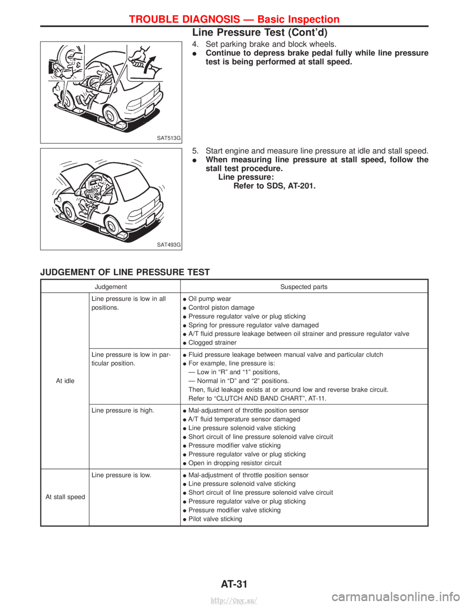
4. Set parking brake and block wheels.
IContinue to depress brake pedal fully while line pressure
test is being performed at stall speed.
5. Start engine and measure line pressure at idle and stall speed.
I When measuring line pressure at stall speed, follow the
stall test procedure.
Line pressure: Refer to SDS, AT-201.
JUDGEMENT OF LINE PRESSURE TEST
Judgement Suspected parts
At idle Line pressure is low in all
positions.
I
Oil pump wear
I Control piston damage
I Pressure regulator valve or plug sticking
I Spring for pressure regulator valve damaged
I A/T fluid pressure leakage between oil strainer and pressure regulator valve
I Clogged strainer
Line pressure is low in par-
ticular position. I
Fluid pressure leakage between manual valve and particular clutch
I For example, line pressure is:
Ð Low in ªRº and ª1º positions,
Ð Normal in ªDº and ª2º positions.
Then, fluid leakage exists at or around low and reverse brake circuit.
Refer to ªCLUTCH AND BAND CHARTº, AT-11.
Line pressure is high. IMal-adjustment of throttle position sensor
I A/T fluid temperature sensor damaged
I Line pressure solenoid valve sticking
I Short circuit of line pressure solenoid valve circuit
I Pressure modifier valve sticking
I Pressure regulator valve or plug sticking
I Open in dropping resistor circuit
At stall speed Line pressure is low.
IMal-adjustment of throttle position sensor
I Line pressure solenoid valve sticking
I Short circuit of line pressure solenoid valve circuit
I Pressure regulator valve or plug sticking
I Pressure modifier valve sticking
I Pilot valve sticking
SAT513G
SAT493G
TROUBLE DIAGNOSIS Ð Basic Inspection
Line Pressure Test (Cont'd)
AT-31
http://vnx.su/
Page 856 of 1833
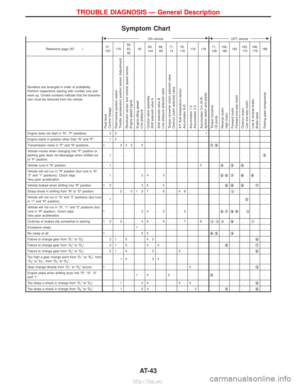
Symptom Chart
FON vehicleEFOFF vehicleE
Reference page (AT- )27,
120 11 9 56,
62,
82 30
65,
144 68,
86 71,
74 78,
11 8 11 8 11 8 71,
128 156,
160 162162,
170 166,
176 180
Numbers are arranged in order of probability.
Perform inspections starting with number one and
work up. Circled numbers indicate that the transmis-
sion must be removed from the vehicle.
Fluid level
Control linkage
Park/neutral position switch
Throttle (accelerator) position sensor (Adjustment)
Revolution sensor and vehicle speed sensor
Engine speed signal
Engine idling speed
Line pressure
Control valve assembly
Shift solenoid valve A
Shift solenoid valve B
Line pressure solenoid valve
Torque converter clutch solenoid valve
Overrun clutch solenoid valve
A/T fluid temperature sensor
Accumulator N-D
Accumulator 1-2
Accumulator 2-3
Accumulator 3-4 (N-R)
Ignition switch and starter
Torque converter
Oil pump
Reverse clutch
High clutch
Forward clutch
Forward one-way clutch
Overrun clutch
Low one-way clutch
Low & reverse brake
Brake band
Parking pawl components
Engine does not start in ªNº, ªPº positions. . 2 3................1. ......... .
Engine starts in position other than ªNº and ªPº. . 1 2 ................. . ......... .
Transmission noise in ªPº and ªNº positions. 1 . . 3 4 5 . 2 ............q
7q6........ .
Vehicle moves when changing into ªPº position or
parking gear does not disengage when shifted out
of ªPº position. . 1.................. .
.........q
2
Vehicle runs in ªNº position.
. 1................2. .. q4.q3.q5... .
Vehicle will not run in ªRº position (but runs in ªDº,
ª2º and ª1º positions). Clutch slips.
Very poor acceleration. . 1.....24..3........ ..
q
5q6q7.q8.q9..
Vehicle braked when shifting into ªRº position. 1 2 .....35..4........ ... q
6q8.q9.. q7.
Sharp shock in shifting from ªNº to ªDº position. . . . 2 . 5137 . . 6 . . 48.... ....q
10..... .
Vehicle will not run in ªDº and ª2º positions (but runs
in ª1º and ªRº position). . 1.................. .
......q
2.. .
Vehicle will not run in ªDº, ª1º and ª2º positions (but
runs in ªRº position). Clutch slips.
Very poor acceleration. 1 ......24..3...5.... ..
q
6q7q8q9.q10.. .
Clutches or brakes slip somewhat in starting. 1 2 . 3 . . . 4 6 . . 5 . . . 7 . . 8 . q
13q12q10.q9... q11..
Excessive creep. . .....1............. . ......... .
No creep at all. 1 ......23........... q
6q5..q4..... .
Failure to change gear from ªD
1ºtoªD2º. . 21.5...43.......... . ........q6.
Failure to change gear from ªD
2ºtoªD3º. . 21.5...4.3......... ... q6.....q7.
Failure to change gear from ªD
3ºtoªD4º. . 21.4....3....5..... . ........q6.
Too high a gear change point from ªD
1ºtoªD2º, from
ªD2ºtoªD3º, from ªD3ºtoªD4º. . ..12....34......... .
......... .
Gear change directly from ªD
1ºtoªD3º occurs. 1 ...............2... . ........q3.
Engine stops when shifting lever into ªRº, ªDº, ª2º
and ª1º. . .....1.3...2.......
q
4......... .
Too sharp a shock in change from ªD
1ºtoªD2º. . ..1...24.....5.3... . ........q6.
Too sharp a shock in change from ªD
2ºtoªD3º. . ..1...24........3.. ... q5.....q6.
TROUBLE DIAGNOSIS Ð General Description
AT-43
http://vnx.su/
Page 857 of 1833
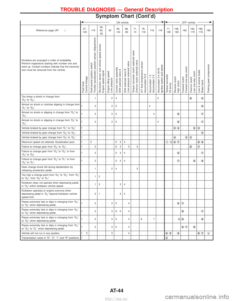
FON vehicleEFOFF vehicleE
Reference page (AT- )27,
120 11 9 56,
62,
82 30
65,
144 68,
86 71,
74 78,
11 8 11 8 11 8 71,
128 156,
160 162162,
170 166,
176 180
Numbers are arranged in order of probability.
Perform inspections starting with number one and
work up. Circled numbers indicate that the transmis-
sion must be removed from the vehicle.
Fluid level
Control linkage
Park/neutral position switch
Throttle (accelerator) position sensor (Adjustment)
Revolution sensor and vehicle speed sensor
Engine speed signal
Engine idling speed
Line pressure
Control valve assembly
Shift solenoid valve A
Shift solenoid valve B
Line pressure solenoid valve
Torque converter clutch solenoid valve
Overrun clutch solenoid valve
A/T fluid temperature sensor
Accumulator N-D
Accumulator 1-2
Accumulator 2-3
Accumulator 3-4 (N-R)
Ignition switch and starter
Torque converter
Oil pump
Reverse clutch
High clutch
Forward clutch
Forward one-way clutch
Overrun clutch
Low one-way clutch
Low & reverse brake
Brake band
Parking pawl components
Too sharp a shock in change from
ªD3ºtoªD4º. . ..1...24.........3. .
.....q6..q5.
Almost no shock or clutches slipping in change from
ªD
1ºtoªD2º. 1 ..2...35.......4... .
........q6.
Almost no shock or slipping in change from ªD
2ºto
ªD3º. 1 ..2...35........4.. ...
q6.....q7.
Almost no shock or slipping in change from ªD
3ºto
ªD4º. 1 ..2...35.........4. ...
q6.....q7.
Vehicle braked by gear change from ªD
1ºtoªD2º. 1 ................... .. q2q4...q5q3..
Vehicle braked by gear change from ªD
2ºtoªD3º. 1 ................... . ........q2.
Vehicle braked by gear change from ªD
3ºtoªD4º. 1 ................... .. q4..q3q2... .
Maximum speed not attained. Acceleration poor. 1 . 2 .....534.........q
11q10q6q7....q9q8.
Failure to change gear from ªD
4ºtoªD3º. 1 ..2....64.5.3...... . .....q8.q7..
Failure to change gear from ªD
3ºtoªD2º or from
ªD4ºtoªD2º. 1 ..2....534......... ...
q6.....q7.
Failure to change gear from ªD
2ºtoªD1º or from
ªD3ºtoªD1º. 1 ..2....534......... ...
q7...q6.q8.
Gear change shock felt during deceleration by
releasing accelerator pedal. . ..1...24....3...... .
......... .
Too high a change point from ªD
4ºtoªD3º, from ªD3º
to ªD2º, from ªD2ºtoªD1º. . ..12............... .
......... .
Kickdown does not operate when depressing pedal
in ªD
4º within kickdown vehicle speed. . ..12....34......... .
......... .
Kickdown operates or engine overruns when
depressing pedal in ªD
4º beyond kickdown vehicle
speed limit. . ..21....34......... .
......... .
Races extremely fast or slips in changing from ªD
4º
to ªD3º when depressing pedal. 1 ..2...35..4........ ...
q6q7..... .
Races extremely fast or slips in changing from ªD
4º
to ªD2º when depressing pedal. 1 ..2...365.4........ ....
q8....q7.
Races extremely fast or slips in changing from ªD
3º
to ªD2º when depressing pedal. 1 ..2...35..4..6..7.. ...
q10q9....q8.
Races extremely fast or slips in changing from ªD
4º
or ªD3ºtoªD1º when depressing pedal. 1 ..2...35..4........ ....
q6q7.q8.. .
Vehicle will not run in any position. 1 2 .....3...4........ q
9q5.q6.... q8q7q10
Transmission noise in ªDº, ª2º, ª1º and ªRº positions. 1
................... q2......... .
TROUBLE DIAGNOSIS Ð General Description
Symptom Chart (Cont'd)
AT-44
http://vnx.su/