Arm tightening torque NISSAN TERRANO 2004 Service Repair Manual
[x] Cancel search | Manufacturer: NISSAN, Model Year: 2004, Model line: TERRANO, Model: NISSAN TERRANO 2004Pages: 1833, PDF Size: 53.42 MB
Page 1142 of 1833
INSTALLATION AND ADJUSTMENT
Adjustment of anchor arm adjusting nut is in tightening direc-
tion only.
Do not adjust by loosening anchor arm adjusting nut.
1. Coat multi-purpose grease on the serration of torsion barspring.
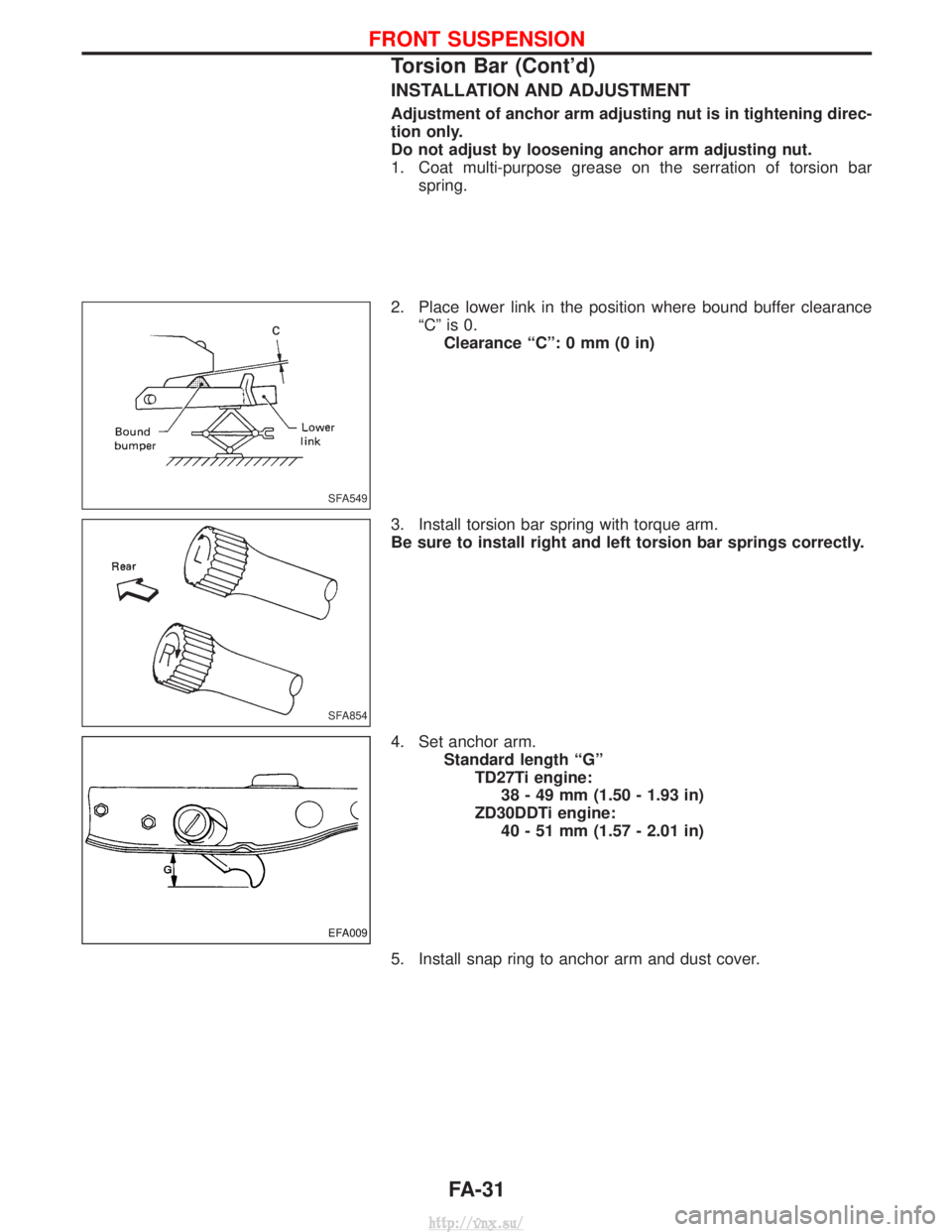
2. Place lower link in the position where bound buffer clearance ªCº is 0.Clearance ªCº: 0 mm (0 in)
3. Install torsion bar spring with torque arm.
Be sure to install right and left torsion bar springs correctly.
4. Set anchor arm. Standard length ªGºTD27Ti engine:38 - 49 mm (1.50 - 1.93 in)
ZD30DDTi engine: 40 - 51 mm (1.57 - 2.01 in)
5. Install snap ring to anchor arm and dust cover.
SFA549
SFA854
EFA009
FRONT SUSPENSION
Torsion Bar (Cont'd)
FA-31
http://vnx.su/
Page 1150 of 1833
Inspection and Adjustment
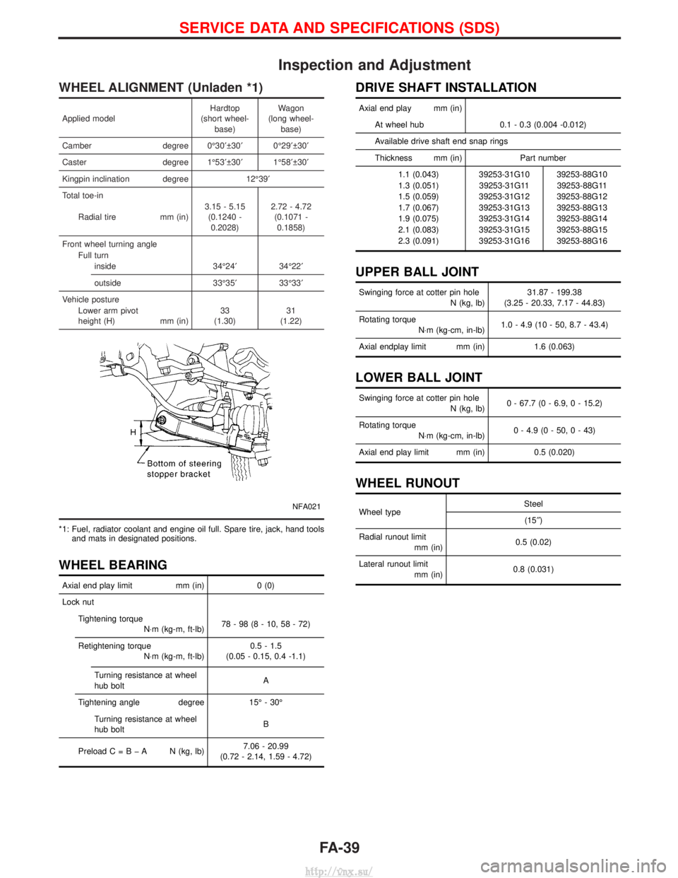
WHEEL ALIGNMENT (Unladen *1)
Applied modelHardtop
(short wheel- base) Wagon
(long wheel- base)
Camber degree 0É30¢ 30¢0É29¢ 30¢
Caster degree 1É53¢ 30¢1É58¢ 30¢
Kingpin inclination degree 12É39¢
Total toe-in
Radial tire mm (in)3.15 - 5.15
(0.1240 -0.2028) 2.72 - 4.72
(0.1071 -0.1858)
Front wheel turning angle Full turninside 34É24¢34É22¢
outside 33É35¢33É33¢
Vehicle posture Lower arm pivot
height (H) mm (in)33
(1.30) 31
(1.22)
NFA021
*1: Fuel, radiator coolant and engine oil full. Spare tire, jack, hand tools and mats in designated positions.
WHEEL BEARING
Axial end play limit mm (in)0 (0)
Lock nut Tightening torque N×m (kg-m, ft-lb) 78-98(8-10,58-72)
Retightening torque N×m (kg-m, ft-lb) 0.5 - 1.5
(0.05 - 0.15, 0.4 -1.1)
Turning resistance at wheel
hub bolt A
Tightening angle degree 15É - 30É
Turning resistance at wheel
hub bolt B
PreloadC=BþA N(kg, lb) 7.06 - 20.99
(0.72 - 2.14, 1.59 - 4.72)
DRIVE SHAFT INSTALLATION
Axial end play mm (in)
At wheel hub 0.1 - 0.3 (0.004 -0.012)
Available drive shaft end snap rings
Thickness mm (in) Part number 1.1 (0.043) 39253-31G10 39253-88G10
1.3 (0.051) 39253-31G11 39253-88G11
1.5 (0.059) 39253-31G12 39253-88G12
1.7 (0.067) 39253-31G13 39253-88G13
1.9 (0.075) 39253-31G14 39253-88G14
2.1 (0.083) 39253-31G15 39253-88G15
2.3 (0.091) 39253-31G16 39253-88G16
UPPER BALL JOINT
Swinging force at cotter pin hole N (kg, lb)31.87 - 199.38
(3.25 - 20.33, 7.17 - 44.83)
Rotating torque N×m (kg-cm, in-lb) 1.0 - 4.9 (10 - 50, 8.7 - 43.4)
Axial endplay limit mm (in) 1.6 (0.063)
LOWER BALL JOINT
Swinging force at cotter pin hole
N (kg, lb)0 - 67.7 (0 - 6.9, 0 - 15.2)
Rotating torque N×m (kg-cm, in-lb) 0 - 4.9 (0 - 50, 0 - 43)
Axial end play limit mm (in) 0.5 (0.020)
WHEEL RUNOUT
Wheel type Steel
(15² )
Radial runout limit mm (in) 0.5 (0.02)
Lateral runout limit mm (in) 0.8 (0.031)
SERVICE DATA AND SPECIFICATIONS (SDS)
FA-39
http://vnx.su/
Page 1609 of 1833
Installation
1. Prior to wiper arm installation, turn on wiper switch to operatewiper motor and then turn it ªOFFº (Auto Stop).
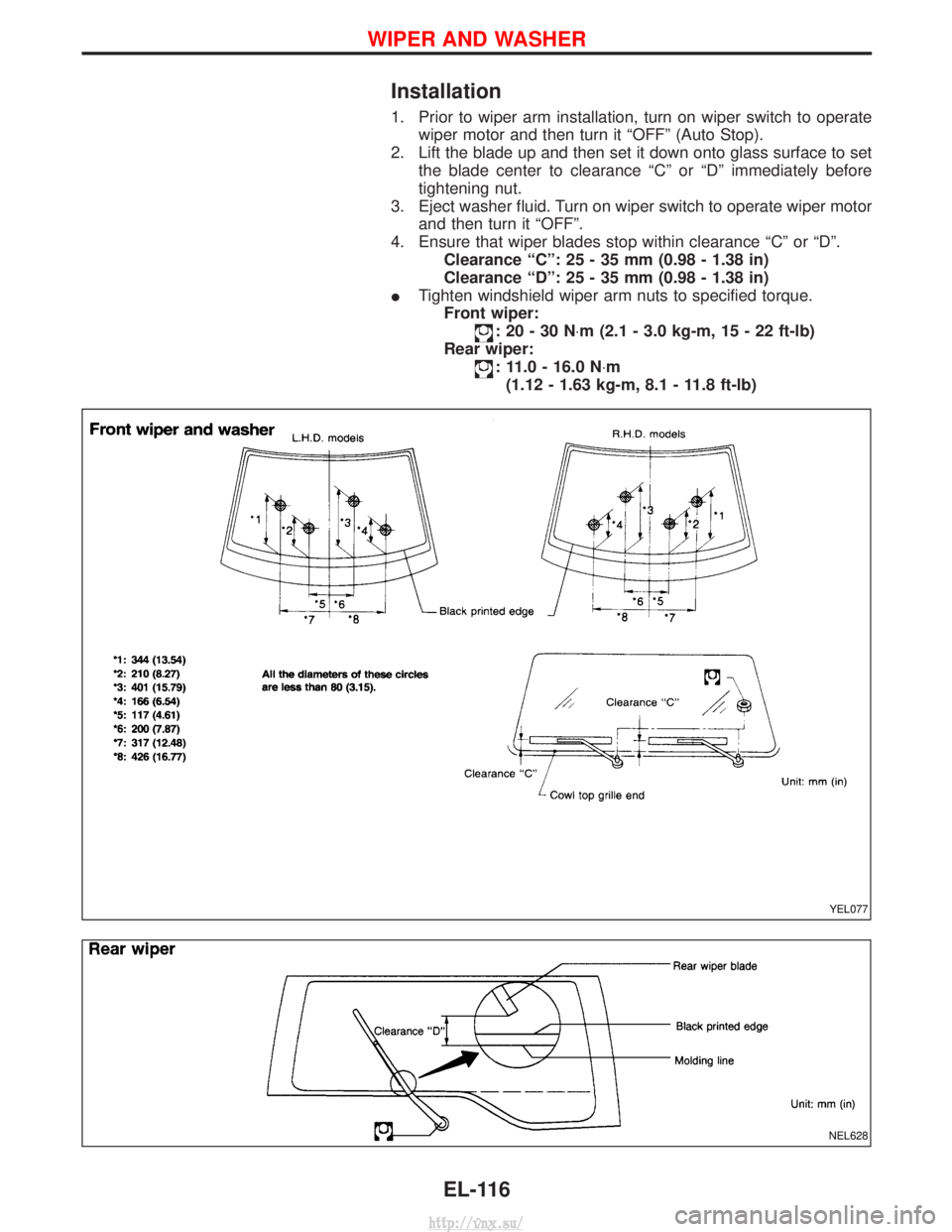
2. Lift the blade up and then set it down onto glass surface to set the blade center to clearance ªCº or ªDº immediately before
tightening nut.
3. Eject washer fluid. Turn on wiper switch to operate wiper motor and then turn it ªOFFº.
4. Ensure that wiper blades stop within clearance ªCº or ªDº. Clearance ªCº: 25 - 35 mm (0.98 - 1.38 in)
Clearance ªDº: 25 - 35 mm (0.98 - 1.38 in)
I Tighten windshield wiper arm nuts to specified torque.
Front wiper:
:20-30N ×m (2.1 - 3.0 kg-m, 15 - 22 ft-lb)
Rear wiper:
: 11.0 - 16.0 N ×m
(1.12 - 1.63 kg-m, 8.1 - 11.8 ft-lb)
YEL077
NEL628
WIPER AND WASHER
EL-116
http://vnx.su/