Combination meter connection NISSAN TERRANO 2004 Service Repair Manual
[x] Cancel search | Manufacturer: NISSAN, Model Year: 2004, Model line: TERRANO, Model: NISSAN TERRANO 2004Pages: 1833, PDF Size: 53.42 MB
Page 692 of 1833
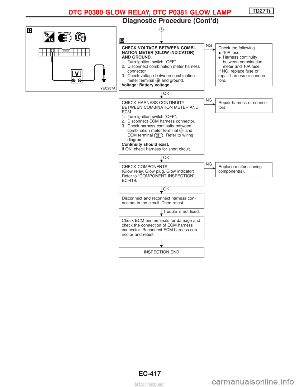
qA
CHECK VOLTAGE BETWEEN COMBI-
NATION METER (GLOW INDICATOR)
AND GROUND.
1. Turn ignition switch ªOFFº.
2. Disconnect combination meter harness connector.
3. Check voltage between combination meter terminal q
28and ground.
Voltage: Battery voltage
OK
ENG Check the following.
I10A fuse
I Harness continuity
between combination
meter and 10A fuse
If NG, replace fuse or
repair harness or connec-
tors.
CHECK HARNESS CONTINUITY
BETWEEN COMBINATION METER AND
ECM.
1. Turn ignition switch ªOFFº.
2. Disconnect ECM harness connector.
3. Check harness continuity between combination meter terminal q
47and
ECM terminal221. Refer to wiring
diagram.
Continuity should exist.
If OK, check harness for short circuit.
OK
ENG Repair harness or connec-
tors.
CHECK COMPONENTS.
(Glow relay, Glow plug, Glow indicator).
Refer to ªCOMPONENT INSPECTIONº,
EC-419.
OK
ENGReplace malfunctioning
component(s).
Disconnect and reconnect harness con-
nectors in the circuit. Then retest.
Trouble is not fixed.
Check ECM pin terminals for damage and
check the connection of ECM harness
connector. Reconnect ECM harness con-
nector and retest.
INSPECTION END
YEC257A
H
H
H
H
H
H
DTC P0380 GLOW RELAY, DTC P0381 GLOW LAMPTD27Ti
Diagnostic Procedure (Cont'd)
EC-417
http://vnx.su/
Page 697 of 1833
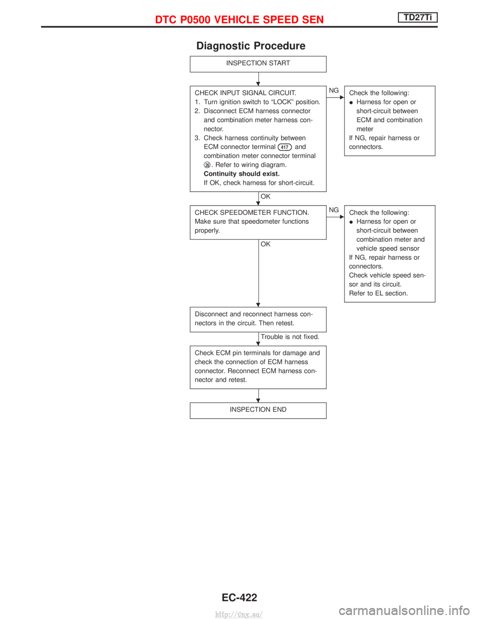
Diagnostic Procedure
INSPECTION START
CHECK INPUT SIGNAL CIRCUIT.
1. Turn ignition switch to ªLOCKº position.
2. Disconnect ECM harness connector and combination meter harness con-
nector.
3. Check harness continuity between ECM connector terminal
417and
combination meter connector terminal
q
26. Refer to wiring diagram.
Continuity should exist.
If OK, check harness for short-circuit.
OK
ENG Check the following:
IHarness for open or
short-circuit between
ECM and combination
meter
If NG, repair harness or
connectors.
CHECK SPEEDOMETER FUNCTION.
Make sure that speedometer functions
properly.
OK
ENG Check the following:
IHarness for open or
short-circuit between
combination meter and
vehicle speed sensor
If NG, repair harness or
connectors.
Check vehicle speed sen-
sor and its circuit.
Refer to EL section.
Disconnect and reconnect harness con-
nectors in the circuit. Then retest.
Trouble is not fixed.
Check ECM pin terminals for damage and
check the connection of ECM harness
connector. Reconnect ECM harness con-
nector and retest.
INSPECTION END
H
H
H
H
H
DTC P0500 VEHICLE SPEED SENTD27Ti
EC-422
http://vnx.su/
Page 704 of 1833
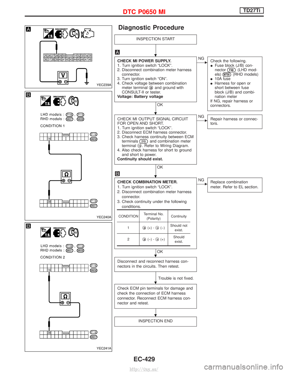
Diagnostic Procedure
INSPECTION START
CHECK MI POWER SUPPLY.
1. Turn ignition switch ªLOCKº.
2. Disconnect combination meter harness connector.
3. Turn ignition switch ªONº.
4. Check voltage between combination meter terminal q
28and ground with
CONSULT-II or tester.
Voltage: Battery voltage
OK
ENG Check the following.
IFuse block (J/B) con-
nector
F48(LHD mod-
els)M756(RHD models)
I 10A fuse
I Harness for open or
short between fuse
block (J/B) and combi-
nation meter
If NG, repair harness or
connectors.
CHECK MI OUTPUT SIGNAL CIRCUIT
FOR OPEN AND SHORT.
1. Turn ignition switch ªLOCKº.
2. Disconnect ECM harness connector.
3. Check harness continuity between ECM terminals
215and combination meter
terminal q14. Refer to Wiring Diagram.
4. Also check harness for short to ground and short to power.
Continuity should exist.
OK
ENG Repair harness or connec-
tors.
CHECK COMBINATION METER.
1. Turn ignition switch ªLOCKº.
2. Disconnect combination meter harness connector.
3. Check continuity under the following conditions.
OK
ENG Replace combination
meter. Refer to EL section.
Disconnect and reconnect harness con-
nectors in the circuits. Then retest.
Trouble is not fixed.
Check ECM pin terminals for damage and
check the connection of ECM harness
connector. Reconnect ECM harness con-
nector and retest.
INSPECTION END
CONDITION Terminal No.
(Polarity) Continuity
1 q
28(+) -q14(þ) Should not
exist.
2 q
28(þ) -q14(+) Should
exist.
YEC239A
YEC240A
YEC241A
H
H
H
H
H
H
DTC P0650 MITD27Ti
EC-429
http://vnx.su/
Page 1236 of 1833
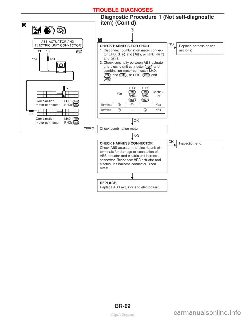
qA
CHECK HARNESS FOR SHORT.
1. Disconnect combination meter connec-tor LHD:
F118andF119, or RHD:M837
andM838.
2. Check continuity between ABS actuator and electric unit connector
F29and
combination meter connector LHD:
F118andF119, or RHD:M837and
M838.
OK
ENG Replace harness or con-
nector(s).
Check combination meter
NG
CHECK HARNESS CONNECTOR.
Check ABS actuator and electric unit pin
terminals for damage or connection of
ABS actuator and electric unit harness
connector. Reconnect ABS actuator and
electric unit harness connector. Then
retest.
EOK Inspection end
REPLACE.
Replace ABS actuator and electric unit.
F29 LHD:F119RHD:M838
LHD:F118RHD:M837
Continu-
ity
Terminal q
13q1ÐYes
Terminal q
21Ðq44Ye s
YBR270
H
H
H
H
TROUBLE DIAGNOSES
Diagnostic Procedure 1 (Not self-diagnostic
item) (Cont'd)
BR-69
http://vnx.su/
Page 1628 of 1833
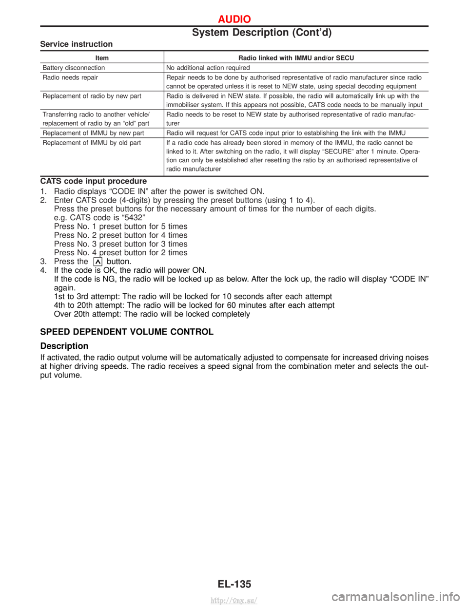
Service instruction
ItemRadio linked with IMMU and/or SECU
Battery disconnection No additional action required
Radio needs repair Repair needs to be done by authorised representative of radio manufacturer since radio cannot be operated unless it is reset to NEW state, using special decoding equipment
Replacement of radio by new part Radio is delivered in NEW state. If possible, the radio will automatically link up with the immobiliser system. If this appears not possible, CATS code needs to be manually input
Transferring radio to another vehicle/
replacement of radio by an ªoldº part Radio needs to be reset to NEW state by authorised representative of radio manufac-
turer
Replacement of IMMU by new part Radio will request for CATS code input prior to establishing the link with the IMMU
Replacement of IMMU by old part If a radio code has already been stored in memory of the IMMU, the radio cannot be linked to it. After switching on the radio, it will display ªSECUREº after 1 minute. Opera-
tion can only be established after resetting the ratio by an authorised representative of
radio manufacturer
CATS code input procedure
1. Radio displays ªCODE INº after the power is switched ON.
2. Enter CATS code (4-digits) by pressing the preset buttons (using 1 to 4).Press the preset buttons for the necessary amount of times for the number of each digits.
e.g. CATS code is ª5432º
Press No. 1 preset button for 5 times
Press No. 2 preset button for 4 times
Press No. 3 preset button for 3 times
Press No. 4 preset button for 2 times
3. Press the
button.
4. If the code is OK, the radio will power ON. If the code is NG, the radio will be locked up as below. After the lock up, the radio will display ªCODE INº
again.
1st to 3rd attempt: The radio will be locked for 10 seconds after each attempt
4th to 20th attempt: The radio will be locked for 60 minutes after each attempt
Over 20th attempt: The radio will be locked completely
SPEED DEPENDENT VOLUME CONTROL
Description
If activated, the radio output volume will be automatically adjusted to compensate for increased driving noises
at higher driving speeds. The radio receives a speed signal from the combination meter and selects the out-
put volume.
AUDIO
System Description (Cont'd)
EL-135
http://vnx.su/
Page 1831 of 1833
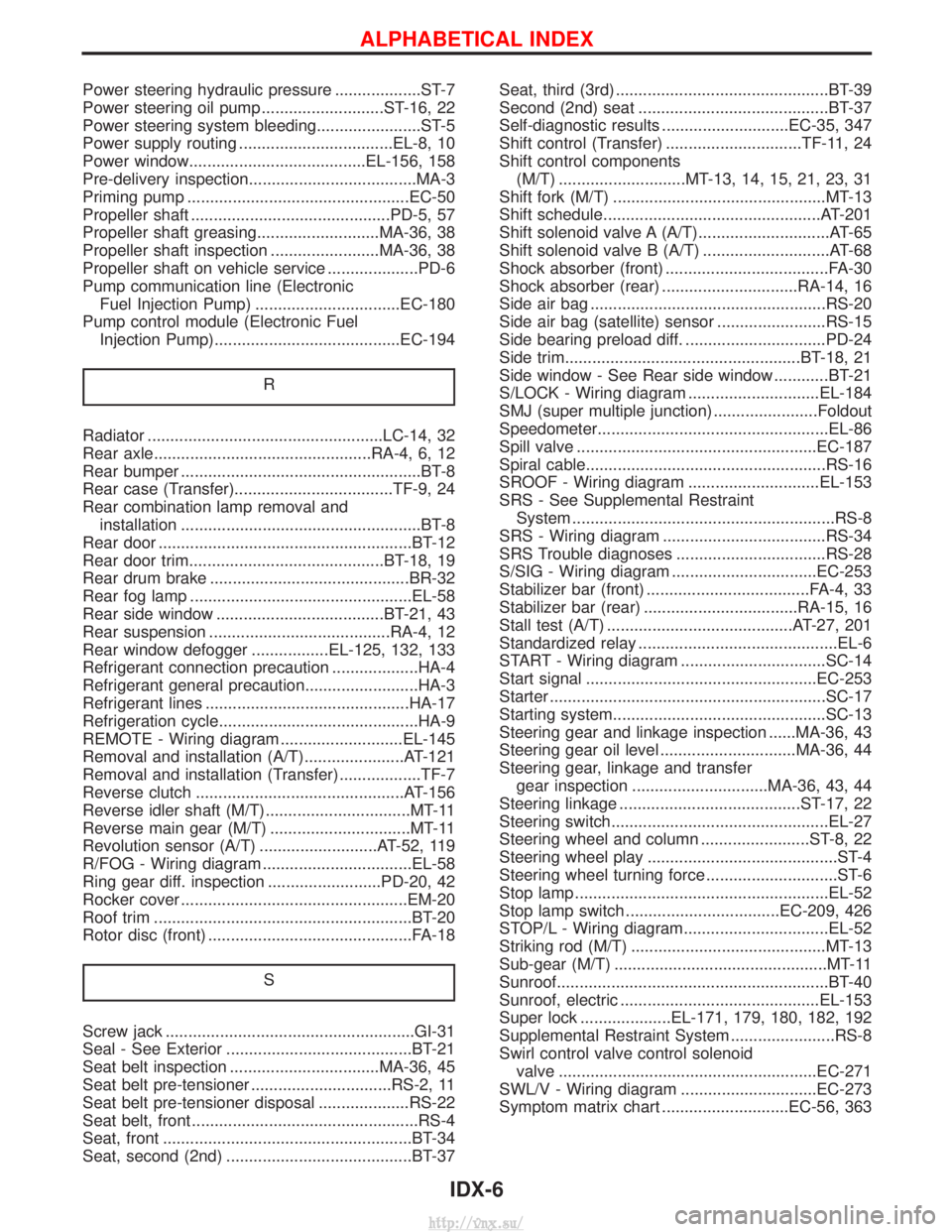
Power steering hydraulic pressure ...................ST-7
Power steering oil pump ...........................ST-16, 22
Power steering system bleeding.......................ST-5
Power supply routing ..................................EL-8, 10
Power window.......................................EL-156, 158
Pre-delivery inspection.....................................MA-3
Priming pump .................................................EC-50
Propeller shaft ............................................PD-5, 57
Propeller shaft greasing...........................MA-36, 38
Propeller shaft inspection ........................MA-36, 38
Propeller shaft on vehicle service ....................PD-6
Pump communication line (ElectronicFuel Injection Pump) ................................EC-180
Pump control module (Electronic Fuel Injection Pump).........................................EC-194
R
Radiator ....................................................LC-14, 32
Rear axle................................................RA-4, 6, 12
Rear bumper .....................................................BT-8
Rear case (Transfer)...................................TF-9, 24
Rear combination lamp removal andinstallation .....................................................BT-8
Rear door ........................................................BT-12
Rear door trim...........................................BT-18, 19
Rear drum brake ............................................BR-32
Rear fog lamp .................................................EL-58
Rear side window .....................................BT-21, 43
Rear suspension ........................................RA-4, 12
Rear window defogger .................EL-125, 132, 133
Refrigerant connection precaution ...................HA-4
Refrigerant general precaution.........................HA-3
Refrigerant lines .............................................HA-17
Refrigeration cycle............................................HA-9
REMOTE - Wiring diagram ...........................EL-145
Removal and installation (A/T)......................AT-121
Removal and installation (Transfer) ..................TF-7
Reverse clutch ..............................................AT-156
Reverse idler shaft (M/T)................................MT-11
Reverse main gear (M/T) ...............................MT-11
Revolution sensor (A/T) ..........................AT-52, 119
R/FOG - Wiring diagram .................................EL-58
Ring gear diff. inspection .........................PD-20, 42
Rocker cover ..................................................EM-20
Roof trim .........................................................BT-20
Rotor disc (front) .............................................FA-18
S
Screw jack .......................................................GI-31
Seal - See Exterior .........................................BT-21
Seat belt inspection .................................MA-36, 45
Seat belt pre-tensioner ...............................RS-2, 11
Seat belt pre-tensioner disposal ....................RS-22
Seat belt, front ..................................................RS-4
Seat, front .......................................................BT-34
Seat, second (2nd) .........................................BT-37 Seat, third (3rd) ...............................................BT-39
Second (2nd) seat ..........................................BT-37
Self-diagnostic results ............................EC-35, 347
Shift control (Transfer) ..............................TF-11, 24
Shift control components
(M/T) ............................MT-13, 14, 15, 21, 23, 31
Shift fork (M/T) ...............................................MT-13
Shift schedule................................................AT-201
Shift solenoid valve A (A/T).............................AT-65
Shift solenoid valve B (A/T) ............................AT-68
Shock absorber (front) ....................................FA-30
Shock absorber (rear) ..............................RA-14, 16
Side air bag ....................................................RS-20
Side air bag (satellite) sensor ........................RS-15
Side bearing preload diff. ...............................PD-24
Side trim....................................................BT-18, 21
Side window - See Rear side window ............BT-21
S/LOCK - Wiring diagram .............................EL-184
SMJ (super multiple junction) .......................Foldout
Speedometer...................................................EL-86
Spill valve .....................................................EC-187
Spiral cable.....................................................RS-16
SROOF - Wiring diagram .............................EL-153
SRS - See Supplemental Restraint System ..........................................................RS-8
SRS - Wiring diagram ....................................RS-34
SRS Trouble diagnoses .................................RS-28
S/SIG - Wiring diagram ................................EC-253
Stabilizer bar (front) ....................................FA-4, 33
Stabilizer bar (rear) ..................................RA-15, 16
Stall test (A/T) .........................................AT-27, 201
Standardized relay ............................................EL-6
START - Wiring diagram ................................SC-14
Start signal ...................................................EC-253
Starter .............................................................SC-17
Starting system...............................................SC-13
Steering gear and linkage inspection ......MA-36, 43
Steering gear oil level ..............................MA-36, 44
Steering gear, linkage and transfer gear inspection ..............................MA-36, 43, 44
Steering linkage ........................................ST-17, 22
Steering switch................................................EL-27
Steering wheel and column ........................ST-8, 22
Steering wheel play ..........................................ST-4
Steering wheel turning force .............................ST-6
Stop lamp ........................................................EL-52
Stop lamp switch ..................................EC-209, 426
STOP/L - Wiring diagram................................EL-52
Striking rod (M/T) ...........................................MT-13
Sub-gear (M/T) ...............................................MT-11
Sunroof............................................................BT-40
Sunroof, electric ............................................EL-153
Super lock ....................EL-171, 179, 180, 182, 192
Supplemental Restraint System .......................RS-8
Swirl control valve control solenoid valve .........................................................EC-271
SWL/V - Wiring diagram ..............................EC-273
Symptom matrix chart ............................EC-56, 363
ALPHABETICAL INDEX
IDX-6
http://vnx.su/