wheel torque NISSAN TERRANO 2004 Service Repair Manual
[x] Cancel search | Manufacturer: NISSAN, Model Year: 2004, Model line: TERRANO, Model: NISSAN TERRANO 2004Pages: 1833, PDF Size: 53.42 MB
Page 4 of 1833
GENERAL INFORMATIONSECTION
GI
CONTENTS
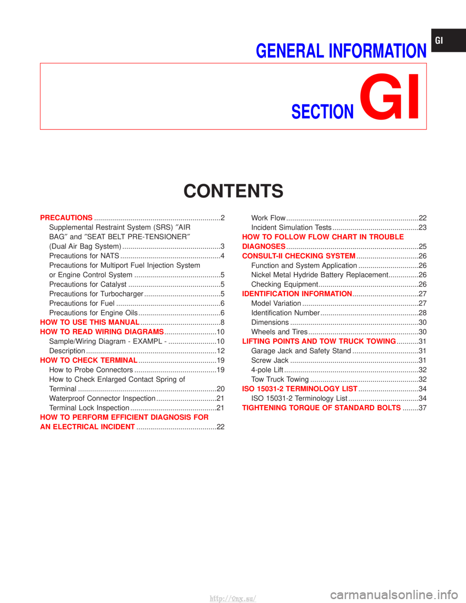
PRECAUTIONS ...............................................................2
Supplemental Restraint System (SRS) ²AIR
BAG² and²SEAT BELT PRE-TENSIONER²
(Dual Air Bag System) .................................................3
Precautions for NATS ..................................................4
Precautions for Multiport Fuel Injection System
or Engine Control System ...........................................5
Precautions for Catalyst ..............................................5
Precautions for Turbocharger ......................................5
Precautions for Fuel ....................................................6
Precautions for Engine Oils .........................................6
HOW TO USE THIS MANUAL ........................................8
HOW TO READ WIRING DIAGRAMS ..........................10
Sample/Wiring Diagram - EXAMPL - ........................10
Description .................................................................12
HOW TO CHECK TERMINAL .......................................19
How to Probe Connectors .........................................19
How to Check Enlarged Contact Spring of
Terminal .....................................................................20
Waterproof Connector Inspection ..............................21
Terminal Lock Inspection ...........................................21
HOW TO PERFORM EFFICIENT DIAGNOSIS FOR
AN ELECTRICAL INCIDENT ........................................22 Work Flow ..................................................................22
Incident Simulation Tests ...........................................23
HOW TO FOLLOW FLOW CHART IN TROUBLE
DIAGNOSES ..................................................................25
CONSULT-II CHECKING SYSTEM ...............................26
Function and System Application ..............................26
Nickel Metal Hydride Battery Replacement...............26
Checking Equipment..................................................26
IDENTIFICATION INFORMATION .................................27
Model Variation ..........................................................27
Identification Number .................................................28
Dimensions ................................................................30
Wheels and Tires .......................................................30
LIFTING POINTS AND TOW TRUCK TOWING ...........31
Garage Jack and Safety Stand .................................31
Screw Jack ................................................................31
4-pole Lift ...................................................................32
Tow Truck Towing ......................................................32
ISO 15031-2 TERMINOLOGY LIST ..............................34
ISO 15031-2 Terminology List ...................................34
TIGHTENING TORQUE OF STANDARD BOLTS ........37
http://vnx.su/
Page 12 of 1833
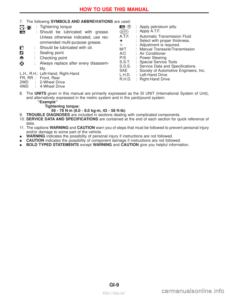
7. The followingSYMBOLS AND ABBREVIATIONS are used:
,: Tightening torque
: Should be lubricated with grease.
Unless otherwise indicated, use rec-
ommended multi-purpose grease.
: Should be lubricated with oil.
: Sealing point
: Checking point
: Always replace after every disassem- bly.
L.H., R.H.: Left-Hand, Right-Hand
FR, RR : Front, Rear
2WD : 2-Wheel Drive
4WD : 4-Wheel Drive
qP: Apply petroleum jelly.
: Apply A.T.F.
A.T.F. : Automatic Transmission Fluid
H : Select with proper thickness.
I : Adjustment is required.
M/T : Manual Transaxle/Transmission
A/C : Air Conditioner
P/S : Power Steering
S.S.T. : Special Service Tools
S.D.S. : Service Data and Specifications
SAE : Society of Automotive Engineers, Inc.
L.H.D. : Left-Hand Drive
R.H.D. : Right-Hand Drive
8. The UNITSgiven in this manual are primarily expressed as the SI UNIT (International System of Unit),
and alternatively expressed in the metric system and in the yard/pound system. ªExampleºTightening torque:59-78N ×m (6.0 - 8.0 kg-m, 43 - 58 ft-lb)
9. TROUBLE DIAGNOSES are included in sections dealing with complicated components.
10. SERVICE DATA AND SPECIFICATIONS are contained at the end of each section for quick reference of
data.
11. The captions WARNINGandCAUTION warn you of steps that must be followed to prevent personal injury
and/or damage to some part of the vehicle.
I WARNING indicates the possibility of personal injury if instructions are not followed.
I CAUTION indicates the possibility of component damage if instructions are not followed.
I BOLD TYPED STATEMENTS exceptWARNING andCAUTION give you helpful information.
HOW TO USE THIS MANUAL
GI-9
http://vnx.su/
Page 42 of 1833
MAINTENANCE
SECTION
MA
CONTENTS
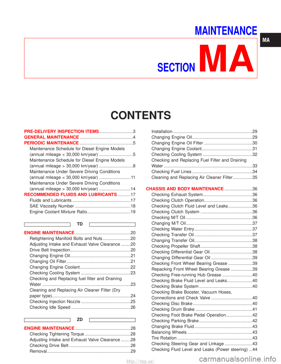
PRE-DELIVERY INSPECTION ITEMS ............................3
GENERAL MAINTENANCE ............................................4
PERIODIC MAINTENANCE ............................................5
Maintenance Schedule for Diesel Engine Models
(annual mileage < 30,000 km/year) ............................5
Maintenance Schedule for Diesel Engine Models
(annual mileage > 30,000 km/year) ............................8
Maintenance Under Severe Driving Conditions
(annual mileage < 30,000 km/year) .......................... 11
Maintenance Under Severe Driving Conditions
(annual mileage > 30,000 km/year) ..........................14
RECOMMENDED FLUIDS AND LUBRICANTS ...........17
Fluids and Lubricants ................................................17
SAE Viscosity Number ..............................................18
Engine Coolant Mixture Ratio....................................19
TD
ENGINE MAINTENANCE ..............................................20
Retightening Manifold Bolts and Nuts .......................20
Adjusting Intake and Exhaust Valve Clearance ........20
Drive Belt Inspection..................................................20
Changing Engine Oil..................................................21
Changing Oil Filter .....................................................21
Changing Engine Coolant..........................................22
Checking Cooling System .........................................23
Checking and Replacing fuel filter and Draining
Water ........................................................................\
.23
Cleaning and Replacing Air Cleaner Filter (Dry
paper type).................................................................24
Checking Injection Nozzle .........................................25
Checking Idle Speed .................................................26
ZD
ENGINE MAINTENANCE ..............................................28
Checking Tightening Torque ......................................28
Adjusting Intake and Exhaust Valve Clearance ........28
Checking Drive Belt ...................................................28
Removal .....................................................................29 Installation ..................................................................29
Changing Engine Oil..................................................29
Changing Engine Oil Filter ........................................30
Changing Engine Coolant..........................................31
Checking Cooling System .........................................32
Checking and Replacing Fuel Filter and Draining
Water ........................................................................\
.33
Checking Fuel Lines ..................................................34
Cleaning and Replacing Air Cleaner Filter ................35
CHASSIS AND BODY MAINTENANCE .......................36
Checking Exhaust System.........................................36
Checking Clutch Operation........................................36
Checking Clutch Fluid Level and Leaks ....................36
Checking Clutch System ...........................................36
Checking M/T Oil .......................................................36
Changing M/T Oil.......................................................37
Checking Water Entry ................................................37
Checking Transfer Oil ................................................37
Changing Transfer Oil................................................38
Checking Propeller Shaft ...........................................38
Checking Differential Gear Oil ...................................38
Changing Differential Gear Oil ..................................39
Checking Front Wheel Bearing Grease ....................39
Repacking Front Wheel Bearing Grease ..................39
Checking Free-running Hub Grease .........................40
Checking Brake Fluid Level and Leaks.....................40
Checking Brake System ............................................40
Checking Brake Booster, Vacuum Hoses,
Connections and Check Valve ..................................40
Checking Disc Brake .................................................40
Checking Drum Brake ...............................................41
Checking Foot Brake Pedal Operation......................42
Checking Parking Brake ............................................42
Changing Brake Fluid ................................................43
Balancing Wheels ......................................................43
Tire Rotation ..............................................................43
Checking Steering Gear and Linkage .......................43
Checking Fluid Level and Leaks (Power steering) ...44
http://vnx.su/
Page 91 of 1833
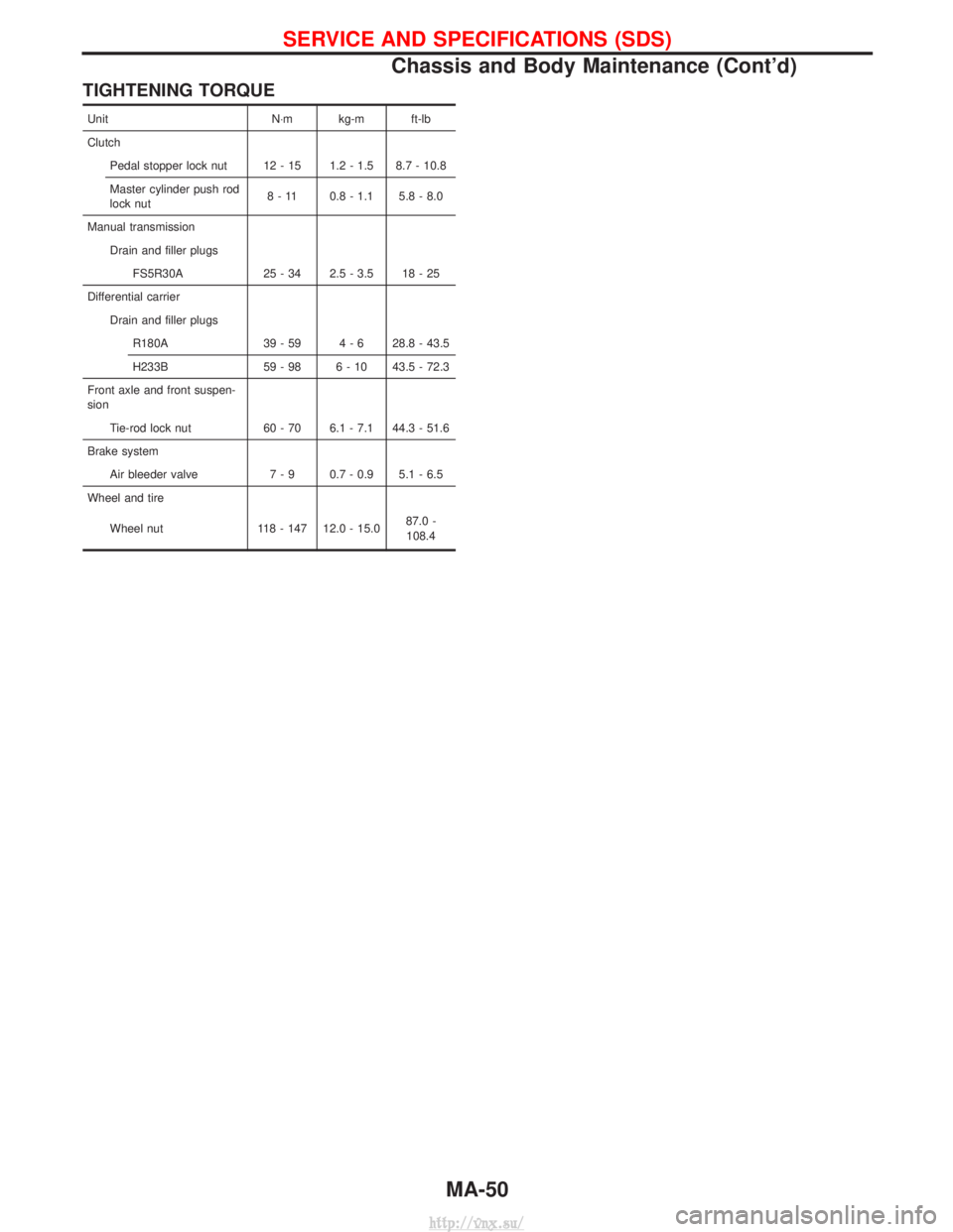
TIGHTENING TORQUE
UnitN×m kg-m ft-lb
Clutch Pedal stopper lock nut 12 - 15 1.2 - 1.5 8.7 - 10.8
Master cylinder push rod
lock nut 8 - 11 0.8 - 1.1 5.8 - 8.0
Manual transmission Drain and filler plugsFS5R30A 25 - 34 2.5 - 3.5 18 - 25
Differential carrier Drain and filler plugsR180A 39 - 59 4 - 6 28.8 - 43.5
H233B 59 - 98 6 - 10 43.5 - 72.3
Front axle and front suspen-
sion Tie-rod lock nut 60 - 70 6.1 - 7.1 44.3 - 51.6
Brake system Air bleeder valve 7 - 9 0.7 - 0.9 5.1 - 6.5
Wheel and tire
Wheel nut 118 - 147 12.0 - 15.0 87.0 -
108.4
SERVICE AND SPECIFICATIONS (SDS)
Chassis and Body Maintenance (Cont'd)
MA-50
http://vnx.su/
Page 818 of 1833
IBefore assembly, apply a coat of recommended ATF to all parts. Apply petroleum jelly to protect O-rings
and seals, and to hold bearings and washers in place during assembly. Do not use grease.
I Extreme care should be taken to avoid damage to O-rings, seals and gaskets when assembling.
I After overhaul, refill the transmission with new ATF.
I When the A/T drain plug is removed, only some of the fluid is drained. Old A/T fluid will remain in torque
converter and ATF cooling system.
Always follow the procedures under ªChanging A/T Fluidº in the MA section when changing A/T fluid.
Service Notice or Precautions
FAIL-SAFE
The TCM has an electronic Fail-Safe (limp home mode). This allows the vehicle to be driven even if a major
electrical input/output device circuit is damaged.
Under Fail-Safe, the vehicle always runs in third gear even with a shift lever position of ª1º, ª2º or ªDº. Cus-
tomer may complain of ªsluggish or poor accelerationº.
When the Fail-Safe operation occurs the next time the key is turned to the ªONº position, the SPORT indica-
tor lamp will blink for about 8 seconds. (For diagnosis, refer to AT-33.)
Fail-Safe may activate without electrical circuit damages if the vehicle is driven under extreme conditions (such
as excessive wheel spins and emergency braking immediately afterwards). In this case, turn the ignition key
ªOFFº for 5 seconds and then ªONº to recover normal shift pattern.
The blinking of the SPORT indicator lamp for about 8 seconds will appear only once and be cleared. The cus-
tomer may resume normal driving conditions by chance.
Always follow the ªWORK FLOWº (Refer to AT-26).
The SELF-DIAGNOSIS results will be as follows:
The first SELF-DIAGNOSIS will indicate the damage of the vehicle speed sensor or the revolution sensor.
During the next SELF-DIAGNOSIS performed after checking the sensor, no damages will be indicated.
PREPARATION AND PRECAUTIONS
Precautions (Cont'd)
AT- 5
http://vnx.su/
Page 1094 of 1833
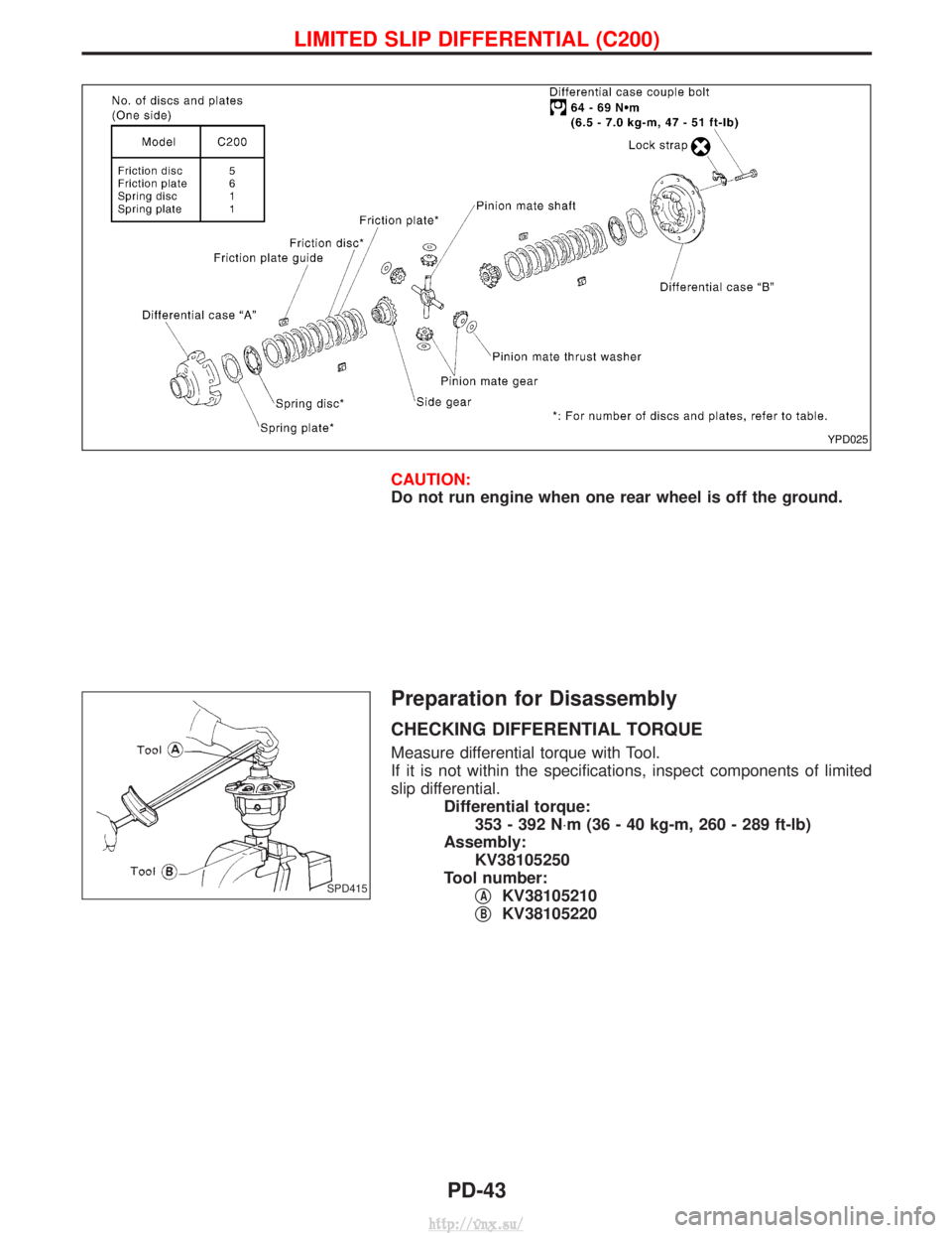
CAUTION:
Do not run engine when one rear wheel is off the ground.
Preparation for Disassembly
CHECKING DIFFERENTIAL TORQUE
Measure differential torque with Tool.
If it is not within the specifications, inspect components of limited
slip differential.Differential torque:353 - 392 N×m (36 - 40 kg-m, 260 - 289 ft-lb)
Assembly: KV38105250
Tool number: q
AKV38105210
q
BKV38105220
YPD025
SPD415
LIMITED SLIP DIFFERENTIAL (C200)
PD-43
http://vnx.su/
Page 1114 of 1833
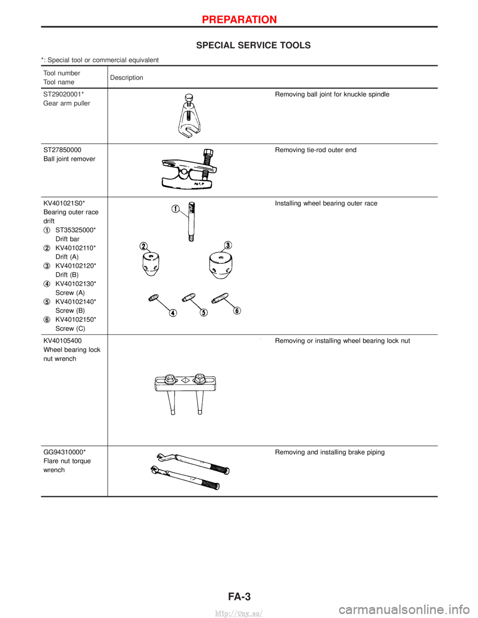
SPECIAL SERVICE TOOLS
*: Special tool or commercial equivalent
Tool number
Tool nameDescription
ST29020001*
Gear arm puller
Removing ball joint for knuckle spindle
ST27850000
Ball joint remover
Removing tie-rod outer end
KV401021S0*
Bearing outer race
drift
q
1ST35325000*
Drift bar
q
2KV40102110*
Drift (A)
q
3KV40102120*
Drift (B)
q
4KV40102130*
Screw (A)
q
5KV40102140*
Screw (B)
q
6KV40102150*
Screw (C)
Installing wheel bearing outer race
KV40105400
Wheel bearing lock
nut wrench
Removing or installing wheel bearing lock nut
GG94310000*
Flare nut torque
wrench
Removing and installing brake piping
PREPARATION
FA-3
http://vnx.su/
Page 1116 of 1833
Front Axle and Front Suspension Parts
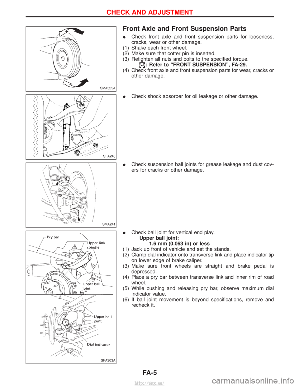
ICheck front axle and front suspension parts for looseness,
cracks, wear or other damage.
(1) Shake each front wheel.
(2) Make sure that cotter pin is inserted.
(3) Retighten all nuts and bolts to the specified torque.
: Refer to ªFRONT SUSPENSIONº, FA-29.
(4) Check front axle and front suspension parts for wear, cracks or other damage.
I Check shock absorber for oil leakage or other damage.
I Check suspension ball joints for grease leakage and dust cov-
ers for cracks or other damage.
I Check ball joint for vertical end play.
Upper ball joint: 1.6 mm (0.063 in) or less
(1) Jack up front of vehicle and set the stands.
(2) Clamp dial indicator onto transverse link and place indicator tip on lower edge of brake caliper.
(3) Make sure front wheels are straight and brake pedal is depressed.
(4) Place a pry bar between transverse link and inner rim of road wheel.
(5) While pushing and releasing pry bar, observe maximum dial indicator value.
(6) If ball joint movement is beyond specifications, remove and recheck it.
SMA525A
SFA240
SMA241
SFA303A
CHECK AND ADJUSTMENT
FA-5
http://vnx.su/
Page 1118 of 1833
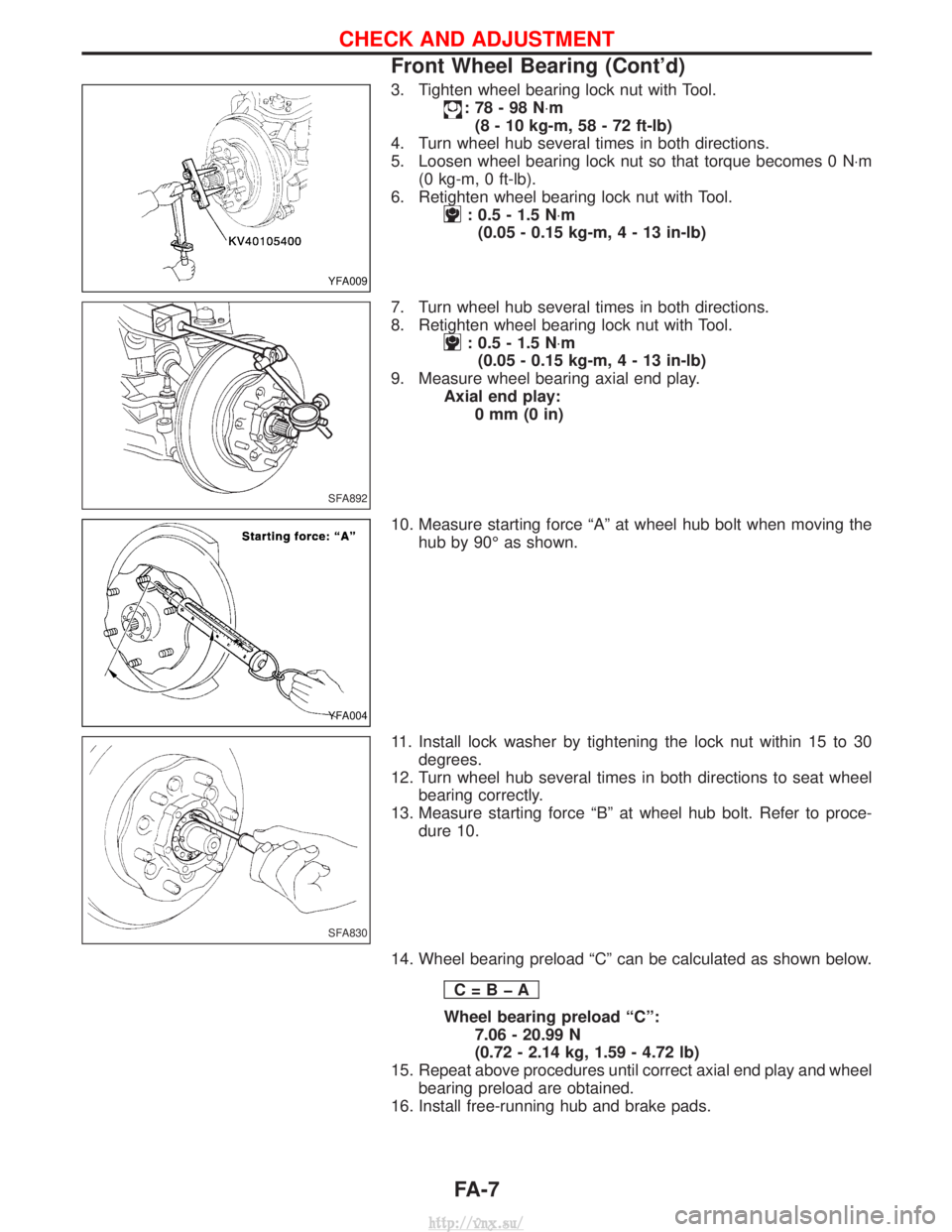
3. Tighten wheel bearing lock nut with Tool.
:78-98N×m
(8 - 10 kg-m, 58 - 72 ft-lb)
4. Turn wheel hub several times in both directions.
5. Loosen wheel bearing lock nut so that torque becomes 0 N ×m
(0 kg-m, 0 ft-lb).
6. Retighten wheel bearing lock nut with Tool.
: 0.5 - 1.5 N ×m
(0.05 - 0.15 kg-m,4-13 in-lb)
7. Turn wheel hub several times in both directions.
8. Retighten wheel bearing lock nut with Tool.
: 0.5 - 1.5 N ×m
(0.05 - 0.15 kg-m,4-13 in-lb)
9. Measure wheel bearing axial end play. Axial end play:0mm(0in)
10. Measure starting force ªAº at wheel hub bolt when moving the hub by 90É as shown.
11. Install lock washer by tightening the lock nut within 15 to 30 degrees.
12. Turn wheel hub several times in both directions to seat wheel bearing correctly.
13. Measure starting force ªBº at wheel hub bolt. Refer to proce- dure 10.
14. Wheel bearing preload ªCº can be calculated as shown below. C=BþA
Wheel bearing preload ªCº:7.06 - 20.99 N
(0.72 - 2.14 kg, 1.59 - 4.72 lb)
15. Repeat above procedures until correct axial end play and wheel bearing preload are obtained.
16. Install free-running hub and brake pads.
YFA009
SFA892
YFA004
SFA830
CHECK AND ADJUSTMENT
Front Wheel Bearing (Cont'd)
FA-7
http://vnx.su/
Page 1122 of 1833
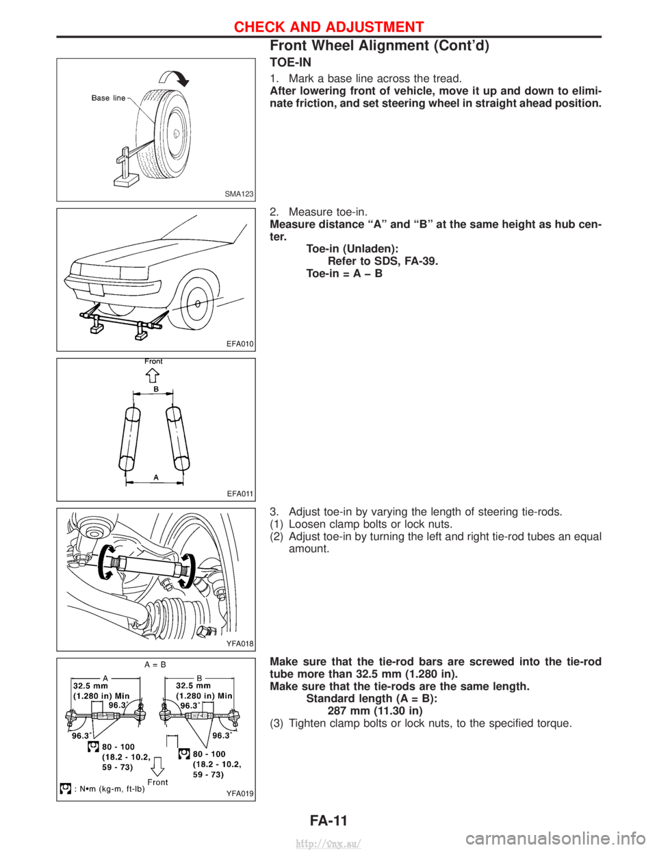
TOE-IN
1. Mark a base line across the tread.
After lowering front of vehicle, move it up and down to elimi-
nate friction, and set steering wheel in straight ahead position.
2. Measure toe-in.
Measure distance ªAº and ªBº at the same height as hub cen-
ter.Toe-in (Unladen):Refer to SDS, FA-39.
Toe-in = A þ B
3. Adjust toe-in by varying the length of steering tie-rods.
(1) Loosen clamp bolts or lock nuts.
(2) Adjust toe-in by turning the left and right tie-rod tubes an equal amount.
Make sure that the tie-rod bars are screwed into the tie-rod
tube more than 32.5 mm (1.280 in).
Make sure that the tie-rods are the same length. Standard length (A = B):287 mm (11.30 in)
(3) Tighten clamp bolts or lock nuts, to the specified torque.
SMA123
EFA010
EFA011
YFA018
YFA019
CHECK AND ADJUSTMENT
Front Wheel Alignment (Cont'd)
FA-11
http://vnx.su/