tire type NISSAN TERRANO 2004 Service Repair Manual
[x] Cancel search | Manufacturer: NISSAN, Model Year: 2004, Model line: TERRANO, Model: NISSAN TERRANO 2004Pages: 1833, PDF Size: 53.42 MB
Page 42 of 1833
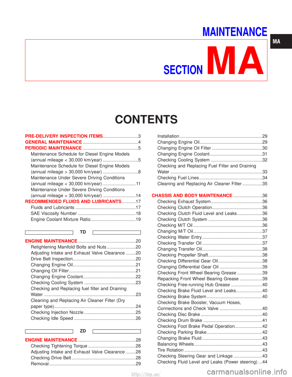
MAINTENANCE
SECTION
MA
CONTENTS
PRE-DELIVERY INSPECTION ITEMS ............................3
GENERAL MAINTENANCE ............................................4
PERIODIC MAINTENANCE ............................................5
Maintenance Schedule for Diesel Engine Models
(annual mileage < 30,000 km/year) ............................5
Maintenance Schedule for Diesel Engine Models
(annual mileage > 30,000 km/year) ............................8
Maintenance Under Severe Driving Conditions
(annual mileage < 30,000 km/year) .......................... 11
Maintenance Under Severe Driving Conditions
(annual mileage > 30,000 km/year) ..........................14
RECOMMENDED FLUIDS AND LUBRICANTS ...........17
Fluids and Lubricants ................................................17
SAE Viscosity Number ..............................................18
Engine Coolant Mixture Ratio....................................19
TD
ENGINE MAINTENANCE ..............................................20
Retightening Manifold Bolts and Nuts .......................20
Adjusting Intake and Exhaust Valve Clearance ........20
Drive Belt Inspection..................................................20
Changing Engine Oil..................................................21
Changing Oil Filter .....................................................21
Changing Engine Coolant..........................................22
Checking Cooling System .........................................23
Checking and Replacing fuel filter and Draining
Water ........................................................................\
.23
Cleaning and Replacing Air Cleaner Filter (Dry
paper type).................................................................24
Checking Injection Nozzle .........................................25
Checking Idle Speed .................................................26
ZD
ENGINE MAINTENANCE ..............................................28
Checking Tightening Torque ......................................28
Adjusting Intake and Exhaust Valve Clearance ........28
Checking Drive Belt ...................................................28
Removal .....................................................................29 Installation ..................................................................29
Changing Engine Oil..................................................29
Changing Engine Oil Filter ........................................30
Changing Engine Coolant..........................................31
Checking Cooling System .........................................32
Checking and Replacing Fuel Filter and Draining
Water ........................................................................\
.33
Checking Fuel Lines ..................................................34
Cleaning and Replacing Air Cleaner Filter ................35
CHASSIS AND BODY MAINTENANCE .......................36
Checking Exhaust System.........................................36
Checking Clutch Operation........................................36
Checking Clutch Fluid Level and Leaks ....................36
Checking Clutch System ...........................................36
Checking M/T Oil .......................................................36
Changing M/T Oil.......................................................37
Checking Water Entry ................................................37
Checking Transfer Oil ................................................37
Changing Transfer Oil................................................38
Checking Propeller Shaft ...........................................38
Checking Differential Gear Oil ...................................38
Changing Differential Gear Oil ..................................39
Checking Front Wheel Bearing Grease ....................39
Repacking Front Wheel Bearing Grease ..................39
Checking Free-running Hub Grease .........................40
Checking Brake Fluid Level and Leaks.....................40
Checking Brake System ............................................40
Checking Brake Booster, Vacuum Hoses,
Connections and Check Valve ..................................40
Checking Disc Brake .................................................40
Checking Drum Brake ...............................................41
Checking Foot Brake Pedal Operation......................42
Checking Parking Brake ............................................42
Changing Brake Fluid ................................................43
Balancing Wheels ......................................................43
Tire Rotation ..............................................................43
Checking Steering Gear and Linkage .......................43
Checking Fluid Level and Leaks (Power steering) ...44
http://vnx.su/
Page 90 of 1833
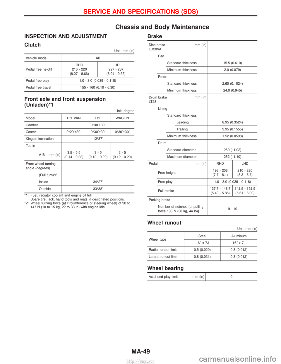
Chassis and Body Maintenance
INSPECTION AND ADJUSTMENT
Clutch
Unit: mm (in)
Vehicle modelAll
Pedal free height RHD
210 - 220
(8.27 - 8.66) LHD
227 - 237
(8.94 - 9.33)
Pedal free play 1.0 - 3.0 (0.039 - 0.118)
Pedal free travel 155 - 160 (6.10 - 6.30)
Front axle and front suspension
(Unladen)*1
Unit: degree
Model H/T VAN H/T WAGON
Camber 0É30¢ 30¢
Caster 0É29¢ 30¢ 0É30¢ 30¢ 0É30¢ 30¢
Kingpin inclination 12É37¢
Toe-in
A-B mm (in) 3.5 - 5.5
(0.14 - 0.22) 3-5
(0.12 - 0.20) 3-5
(0.12 - 0.20)
Front wheel turning
angle (degrees) (Full turn)*2
Inside 34É27¢
Outside 33É38¢
*1: Fuel, radiator coolant and engine oil full. Spare tire, jack, hand tools and mats in designated positions.
*2: Wheel turning force (at circumference of steering wheel) of 98 to 147 N (10 to 15 kg, 22 to 33 lb) with engine idle.
Brake
Disc brake mm (in)
LD28VA
PadStandard thickness 15.5 (0.610)
Minimum thickness 2.0 (0.079)
Rotor Standard thickness 2.60 (0.1024)
Minimum thickness 24.0 (0.945)
Drum brake mm (in)
LT28 LiningStandard thicknessLeading 8.95 (0.3524)
Trailing 3.95 (0.1555)
Minimum thickness 1.52 (0.0598)
Drum Standard diameter 280 (11.02)
Maximum diameter 282 (11.10)
Pedal mm (in) RHD LHD
Free height 196 - 206
(7.7 - 8.1) 210 - 220
(8.3 - 8.7)
Free play 1.0 - 3.0 (0.039 - 0.118)
Full stroke 137.7 - 148.7
(5.42 - 5.85) 142.5 - 152.5
(5.61 - 6.00)
Parking brake Number of notches [at pulling
force 196 N (20 kg, 44 lb)] 9-10
Wheel runout
Unit: mm (in)
Wheel typeSteel Aluminum
16² x7J 16 ²x7J
Radial runout limit 0.5 (0.020) 0.3 (0.012)
Lateral runout limit 0.8 (0.031) 0.3 (0.012)
Wheel bearing
Axial end play limit mm (in) 0
SERVICE AND SPECIFICATIONS (SDS)
MA-49
http://vnx.su/
Page 817 of 1833
Supplemental Restraint System (SRS) ªAIR
BAGº and ªSEAT BELT PRE-TENSIONERº
The Supplemental Restraint System such as ªAIR BAGº and ªSEAT BELT PRE-TENSIONERº used along with
a seat belt, helps to reduce the risk or severity of injury to the driver and front passenger for certain types of
collision. The SRS composition which is available to NISSAN MODEL R20 is as follows (The composition
varies according to the destination and optional equipment.):
IFor a frontal collision
The Supplemental Restraint System consists of driver air bag module (located in the center of the steer-
ing wheel), front passenger air bag module (located on the instrument panel on passenger side), front seat
belt pre-tensioners, a diagnosis sensor unit, warning lamp, wiring harness and spiral cable.
I For a side collision
The Supplemental Restraint System consists of front side air bag module (located in the outer side of front
seat), side air bag (satellite) sensor, diagnosis sensor unit (one of components of air bags for a frontal
collision), wiring harness, warning lamp (one of components of air bags for a frontal collision).
WARNING:
I To avoid rendering the SRS inoperative, which could increase the risk of personal injury or death
in the event of a collision which would result in air bag inflation, all maintenance should be per-
formed by an authorized NISSAN dealer.
I Improper maintenance, including incorrect removal and installation of the SRS, can lead to per-
sonal injury caused by unintentional activation of the system.
I Do not use electrical test equipment on any circuit related to the SRS unless instructed to in this
Service Manual. Spiral cable and wiring harnesses covered with yellow insulation tape either just
before the harness connectors or for the complete harness are related to the SRS.
Precautions for SRS ªAIR BAGº and ªSEAT
BELT PRE-TENSIONERº Service
IDo not use electrical test equipment to check SRS circuits unless instructed to in this Service Manual.
I Before servicing the SRS, turn ignition switch ªOFFº, disconnect both battery cables and wait at least 3
minutes.
For approximately 3 minutes after the cables are removed, it is still possible for the air bag and seat belt
pre-tensioner to deploy. Therefore, do not work on any SRS connectors or wires until at least 3 minutes
have passed.
I Diagnosis sensor unit must always be installed with their arrow marks ª +º pointing towards the front of
the vehicle for proper operation. Also check diagnosis sensor unit for cracks, deformities or rust before
installation and replace as required.
I The spiral cable must be aligned with the neutral position since its rotations are limited. Do not attempt to
turn steering wheel or column after removal of steering gear.
I Handle air bag module carefully. Always place driver and front passenger air bag modules with the pad
side facing upward and place front side air bag module (built-in type) standing with stud bolt side setting
bottom.
I Conduct self-diagnosis to check entire SRS for proper function after replacing any components.
I After air bag inflates, the front instrument panel assembly should be replaced if damaged.
Precautions
IBefore proceeding with disassembly, thoroughly clean the outside of the transmission. It is important to
prevent the internal parts from becoming contaminated by dirt or other foreign matter.
I Disassembly should be done in a clean work area.
I Use lint-free cloth or towels for wiping parts clean. Common shop rags can leave fibers that could inter-
fere with the operation of the transmission.
I Place disassembled parts in order for easier and proper assembly.
I All parts should be carefully cleaned with a general purpose, non-flammable solvent before inspection or
reassembly.
I Gaskets, seals and O-rings should be replaced any time the transmission is disassembled.
I It is very important to perform functional tests whenever they are indicated.
I The valve body contains precision parts and requires extreme care when parts are removed and serviced.
Place removed parts in a parts rack in order to replace them in correct positions and sequences. Care will
also prevent springs and small parts from becoming scattered or lost.
I Properly installed valves, sleeves, plugs, etc. will slide along bores in valve body under their own weight.
PREPARATION AND PRECAUTIONS
AT- 4
http://vnx.su/
Page 1136 of 1833
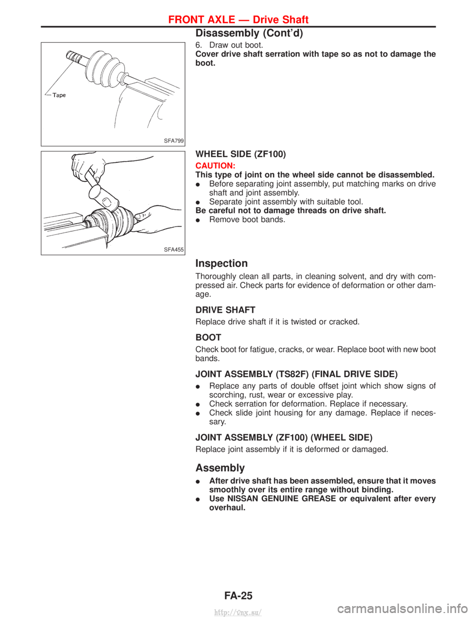
6. Draw out boot.
Cover drive shaft serration with tape so as not to damage the
boot.
WHEEL SIDE (ZF100)
CAUTION:
This type of joint on the wheel side cannot be disassembled.
IBefore separating joint assembly, put matching marks on drive
shaft and joint assembly.
I Separate joint assembly with suitable tool.
Be careful not to damage threads on drive shaft.
I Remove boot bands.
Inspection
Thoroughly clean all parts, in cleaning solvent, and dry with com-
pressed air. Check parts for evidence of deformation or other dam-
age.
DRIVE SHAFT
Replace drive shaft if it is twisted or cracked.
BOOT
Check boot for fatigue, cracks, or wear. Replace boot with new boot
bands.
JOINT ASSEMBLY (TS82F) (FINAL DRIVE SIDE)
IReplace any parts of double offset joint which show signs of
scorching, rust, wear or excessive play.
I Check serration for deformation. Replace if necessary.
I Check slide joint housing for any damage. Replace if neces-
sary.
JOINT ASSEMBLY (ZF100) (WHEEL SIDE)
Replace joint assembly if it is deformed or damaged.
Assembly
IAfter drive shaft has been assembled, ensure that it moves
smoothly over its entire range without binding.
I Use NISSAN GENUINE GREASE or equivalent after every
overhaul.
SFA799
SFA455
FRONT AXLE Ð Drive Shaft
Disassembly (Cont'd)
FA-25
http://vnx.su/
Page 1150 of 1833
Inspection and Adjustment
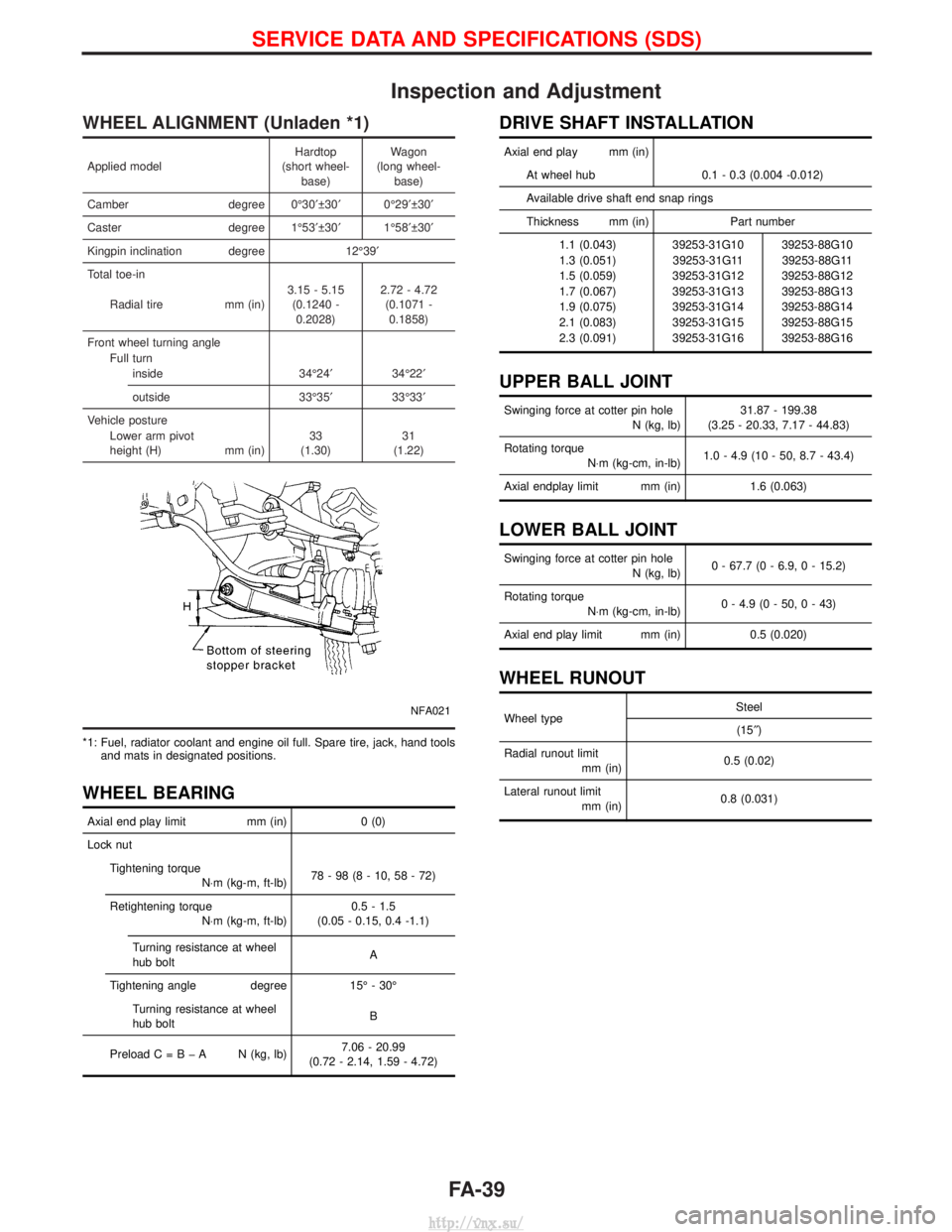
WHEEL ALIGNMENT (Unladen *1)
Applied modelHardtop
(short wheel- base) Wagon
(long wheel- base)
Camber degree 0É30¢ 30¢0É29¢ 30¢
Caster degree 1É53¢ 30¢1É58¢ 30¢
Kingpin inclination degree 12É39¢
Total toe-in
Radial tire mm (in)3.15 - 5.15
(0.1240 -0.2028) 2.72 - 4.72
(0.1071 -0.1858)
Front wheel turning angle Full turninside 34É24¢34É22¢
outside 33É35¢33É33¢
Vehicle posture Lower arm pivot
height (H) mm (in)33
(1.30) 31
(1.22)
NFA021
*1: Fuel, radiator coolant and engine oil full. Spare tire, jack, hand tools and mats in designated positions.
WHEEL BEARING
Axial end play limit mm (in)0 (0)
Lock nut Tightening torque N×m (kg-m, ft-lb) 78-98(8-10,58-72)
Retightening torque N×m (kg-m, ft-lb) 0.5 - 1.5
(0.05 - 0.15, 0.4 -1.1)
Turning resistance at wheel
hub bolt A
Tightening angle degree 15É - 30É
Turning resistance at wheel
hub bolt B
PreloadC=BþA N(kg, lb) 7.06 - 20.99
(0.72 - 2.14, 1.59 - 4.72)
DRIVE SHAFT INSTALLATION
Axial end play mm (in)
At wheel hub 0.1 - 0.3 (0.004 -0.012)
Available drive shaft end snap rings
Thickness mm (in) Part number 1.1 (0.043) 39253-31G10 39253-88G10
1.3 (0.051) 39253-31G11 39253-88G11
1.5 (0.059) 39253-31G12 39253-88G12
1.7 (0.067) 39253-31G13 39253-88G13
1.9 (0.075) 39253-31G14 39253-88G14
2.1 (0.083) 39253-31G15 39253-88G15
2.3 (0.091) 39253-31G16 39253-88G16
UPPER BALL JOINT
Swinging force at cotter pin hole N (kg, lb)31.87 - 199.38
(3.25 - 20.33, 7.17 - 44.83)
Rotating torque N×m (kg-cm, in-lb) 1.0 - 4.9 (10 - 50, 8.7 - 43.4)
Axial endplay limit mm (in) 1.6 (0.063)
LOWER BALL JOINT
Swinging force at cotter pin hole
N (kg, lb)0 - 67.7 (0 - 6.9, 0 - 15.2)
Rotating torque N×m (kg-cm, in-lb) 0 - 4.9 (0 - 50, 0 - 43)
Axial end play limit mm (in) 0.5 (0.020)
WHEEL RUNOUT
Wheel type Steel
(15² )
Radial runout limit mm (in) 0.5 (0.02)
Lateral runout limit mm (in) 0.8 (0.031)
SERVICE DATA AND SPECIFICATIONS (SDS)
FA-39
http://vnx.su/
Page 1255 of 1833
Supplemental Restraint System (SRS) ªAIR
BAGº and ªSEAT BELT PRE-TENSIONERº
The Supplemental Restraint System such as ªAIR BAGº and ªSEAT BELT PRE-TENSIONERº used along with
a seat belt, helps to reduce the risk or severity of injury to the driver and front passenger for certain types of
collision. The SRS composition which is available to NISSAN MODEL R20 is as follows (The composition
varies according to the destination and optional equipment.):
IFor a frontal collision
The Supplemental Restraint System consists of driver air bag module (located in the center of the steer-
ing wheel), front passenger air bag module (located on the instrument panel on passenger side), front seat
belt pre-tensioners, a diagnosis sensor unit, warning lamp, wiring harness and spiral cable.
I For a side collision
The Supplemental Restraint System consists of front side air bag module (located in the outer side of front
seat), side air bag (satellite) sensor, diagnosis sensor unit (one of components of air bags for a frontal
collision), wiring harness, warning lamp (one of components of air bags for a frontal collision).
WARNING:
I To avoid rendering the SRS inoperative, which could increase the risk of personal injury or death
in the event of a collision which would result in air bag inflation, all maintenance should be per-
formed by an authorized NISSAN dealer.
I Improper maintenance, including incorrect removal and installation of the SRS, can lead to per-
sonal injury caused by unintentional activation of the system.
I Do not use electrical test equipment on any circuit related to the SRS unless instructed to in this
Service Manual. Spiral cable and wiring harnesses covered with yellow insulation tape either just
before the harness connectors or for the complete harness are related to the SRS.
Precautions for SRS ªAIR BAGº and ªSEAT
BELT PRE-TENSIONERº Service
IDo not use electrical test equipment to check SRS circuits unless instructed to in this Service Manual.
I Before servicing the SRS, turn ignition switch ªOFFº, disconnect both battery cables and wait at least 3
minutes.
For approximately 3 minutes after the cables are removed, it is still possible for the air bag and seat belt
pre-tensioner to deploy. Therefore, do not work on any SRS connectors or wires until at least 3 minutes
have passed.
I Diagnosis sensor unit must always be installed with their arrow marks ª +º pointing towards the front of
the vehicle for proper operation. Also check diagnosis sensor unit for cracks, deformities or rust before
installation and replace as required.
I The spiral cable must be aligned with the neutral position since its rotations are limited. Do not attempt to
turn steering wheel or column after removal of steering gear.
I Handle air bag module carefully. Always place driver and front passenger air bag modules with the pad
side facing upward and place front side air bag module (built-in type) standing with stud bolt side setting
bottom.
I Conduct self-diagnosis to check entire SRS for proper function after replacing any components.
I After air bag inflates, the front instrument panel assembly should be replaced if damaged.
Precautions for Steering System
IBefore disassembly, thoroughly clean the outside of the unit.
I Disassembly should be done in a clean work area. It is important to prevent the internal parts from
becoming contaminated by dirt or other foreign matter.
I When disassembling parts, be sure to place them in order on a part rack so they can be reinstalled
in their proper positions.
I Use nylon cloths or paper towels to clean the parts; common shop rags can leave lint that might
interfere with their operation.
I Before inspection or reassembly, carefully clean all parts with a general purpose, non-flammable
solvent.
I Before assembly, apply a coat of recommended ATF* to hydraulic parts. Vaseline may be applied
to O-rings and seals. Do not use any grease.
I Replace all gaskets, seals and O-rings. Avoid damaging O-rings, seals and gaskets during instal-
lation. Perform functional tests whenever designated.
*: Automatic transmission fluid
PRECAUTIONS
ST-2
http://vnx.su/
Page 1283 of 1833
Precautions
SUPPLEMENTAL RESTRAINT SYSTEM (SRS) ªAIR BAGº AND ªSEAT BELT
PRE-TENSIONERº
The Supplemental Restraint System such as ªAIR BAGº and ªSEAT BELT PRE-TENSIONERº used along with
a seat belt, helps to reduce the risk or severity of injury to the driver and front passenger for certain types of
collision. The SRS composition which is available to NISSAN MODEL R20 is as follows (The composition
varies according to the destination and optional equipment.):
IFor a frontal collision
The Supplemental Restraint System consists of driver air bag module (located in the center of the steer-
ing wheel), front passenger air bag module (located on the instrument panel on passenger side), front seat
belt pre-tensioners, a diagnosis sensor unit, warning lamp, wiring harness and spiral cable.
I For a side collision
The Supplemental Restraint System consists of front side air bag module (located in the outer side of front
seat), side air bag (satellite) sensor, diagnosis sensor unit (one of components of air bags for a frontal
collision), wiring harness, warning lamp (one of components of air bags for a frontal collision).
WARNING:
I To avoid rendering the SRS inoperative, which could increase the risk of personal injury or death
in the event of a collision which would result in air bag inflation, all maintenance should be per-
formed by an authorized NISSAN dealer.
I Improper maintenance, including incorrect removal and installation of the SRS, can lead to per-
sonal injury caused by unintentional activation of the system.
I Do not use electrical test equipment on any circuit related to the SRS unless instructed to in this
Service Manual. Spiral cable and wiring harnesses covered with yellow insulation tape either just
before the harness connectors or for the complete harness are related to the SRS.
PRECAUTIONS FOR SRS ªAIR BAGº AND ªSEAT BELT PRE-TENSIONERº SERVICE
IDo not use electrical test equipment to check SRS circuits unless instructed to in this Service Manual.
I Before servicing the SRS, turn ignition switch ªOFFº, disconnect both battery cables and wait at least 3
minutes.
For approximately 3 minutes after the cables are removed, it is still possible for the air bag and seat belt
pre-tensioner to deploy. Therefore, do not work on any SRS connectors or wires until at least 3 minutes
have passed.
I Diagnosis sensor unit must always be installed with their arrow marks ª +º pointing towards the front of
the vehicle for proper operation. Also check diagnosis sensor unit for cracks, deformities or rust before
installation and replace as required.
I The spiral cable must be aligned with the neutral position since its rotations are limited. Do not attempt to
turn steering wheel or column after removal of steering gear.
I Handle air bag module carefully. Always place driver and front passenger air bag modules with the pad
side facing upward and place front side air bag module (built-in type) standing with stud bolt side setting
bottom.
I Conduct self-diagnosis to check entire SRS for proper function after replacing any components.
I After air bag inflates, the front instrument panel assembly should be replaced if damaged.
WIRING DIAGRAMS AND TROUBLE DIAGNOSIS
When you read wiring diagrams, refer to the following:
IGI-10, ªHOW TO READ WIRING DIAGRAMSº
I EL-8, ªPOWER SUPPLY ROUTINGº for power distribution circuit
When you perform trouble diagnosis, refer to the following:
I GI-25, ªHOW TO FOLLOW TEST GROUPS IN TROUBLE DIAGNOSISº
I GI-22, ªHOW TO PERFORM EFFICIENT DIAGNOSES FOR AN ELECTRICAL INCIDENTº
SUPPLEMENTAL RESTRAINT SYSTEM (SRS)
RS-8
http://vnx.su/
Page 1540 of 1833
Bulb Replacement
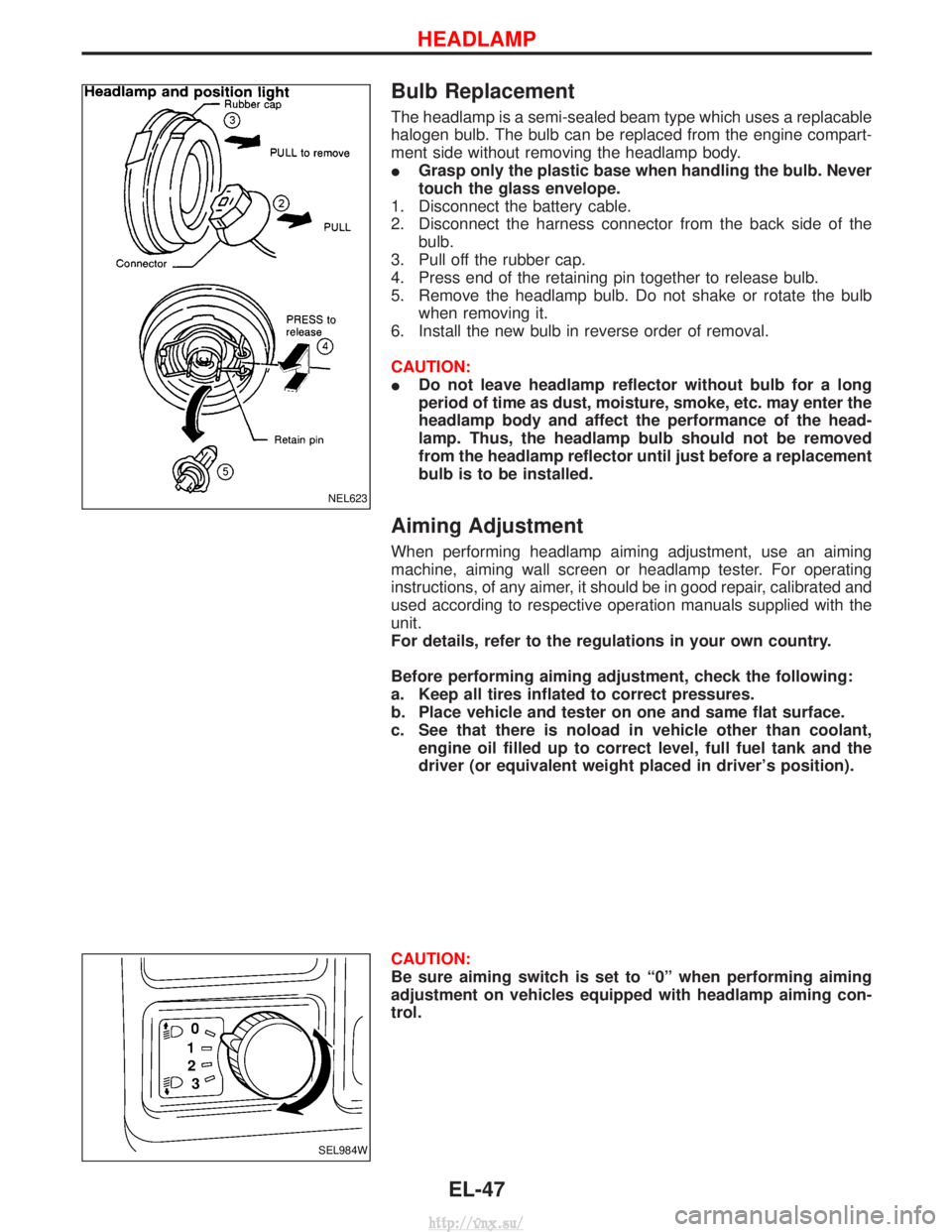
The headlamp is a semi-sealed beam type which uses a replacable
halogen bulb. The bulb can be replaced from the engine compart-
ment side without removing the headlamp body.
IGrasp only the plastic base when handling the bulb. Never
touch the glass envelope.
1. Disconnect the battery cable.
2. Disconnect the harness connector from the back side of the bulb.
3. Pull off the rubber cap.
4. Press end of the retaining pin together to release bulb.
5. Remove the headlamp bulb. Do not shake or rotate the bulb when removing it.
6. Install the new bulb in reverse order of removal.
CAUTION:
I Do not leave headlamp reflector without bulb for a long
period of time as dust, moisture, smoke, etc. may enter the
headlamp body and affect the performance of the head-
lamp. Thus, the headlamp bulb should not be removed
from the headlamp reflector until just before a replacement
bulb is to be installed.
Aiming Adjustment
When performing headlamp aiming adjustment, use an aiming
machine, aiming wall screen or headlamp tester. For operating
instructions, of any aimer, it should be in good repair, calibrated and
used according to respective operation manuals supplied with the
unit.
For details, refer to the regulations in your own country.
Before performing aiming adjustment, check the following:
a. Keep all tires inflated to correct pressures.
b. Place vehicle and tester on one and same flat surface.
c. See that there is noload in vehicle other than coolant,
engine oil filled up to correct level, full fuel tank and the
driver (or equivalent weight placed in driver's position).
CAUTION:
Be sure aiming switch is set to ª0º when performing aiming
adjustment on vehicles equipped with headlamp aiming con-
trol.
NEL623
SEL984W
HEADLAMP
EL-47
http://vnx.su/