dash panel NISSAN TERRANO 2004 Service Repair Manual
[x] Cancel search | Manufacturer: NISSAN, Model Year: 2004, Model line: TERRANO, Model: NISSAN TERRANO 2004Pages: 1833, PDF Size: 53.42 MB
Page 314 of 1833

CONSULT-II
CONSULT-II INSPECTION PROCEDURE
1. Turn ignition switch OFF.
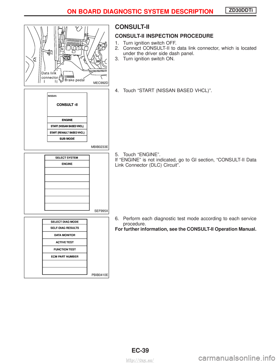
2. Connect CONSULT-II to data link connector, which is locatedunder the driver side dash panel.
3. Turn ignition switch ON.
4. Touch ªSTART (NISSAN BASED VHCL)º.
5. Touch ªENGINEº.
If ªENGINEº is not indicated, go to GI section, ªCONSULT-II Data
Link Connector (DLC) Circuitº.
6. Perform each diagnostic test mode according to each service procedure.
For further information, see the CONSULT-II Operation Manual.
MEC992D
MBIB0233E
SEF995X
PBIB0410E
ON BOARD DIAGNOSTIC SYSTEM DESCRIPTIONZD30DDTi
EC-39
http://vnx.su/
Page 1183 of 1833

Adjustment
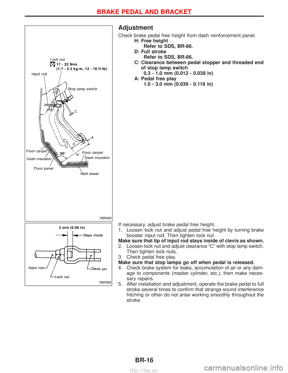
Check brake pedal free height from dash reinforcement panel.H: Free heightRefer to SDS, BR-86.
D: Full stroke Refer to SDS, BR-86.
C: Clearance between pedal stopper and threaded end of stop lamp switch0.3 - 1.0 mm (0.012 - 0.039 in)
A: Pedal free play 1.0 - 3.0 mm (0.039 - 0.118 in)
If necessary, adjust brake pedal free height.
1. Loosen lock nut and adjust pedal free height by turning brake booster input rod. Then tighten lock nut.
Make sure that tip of input rod stays inside of clevis as shown.
2. Loosen lock nut and adjust clearance ªCº with stop lamp switch. Then tighten lock nuts.
3. Check pedal free play.
Make sure that stop lamps go off when pedal is released.
4. Check brake system for leaks, accumulation of air or any dam- age to components (master cylinder, etc.); then make neces-
sary repairs.
5. After installation and adjustment, operate the brake pedal to full stroke several times to confirm that strange sound interference
hitching or other do not arise working smoothly throughout the
stroke.
YBR450
YBR300
BRAKE PEDAL AND BRACKET
BR-16
http://vnx.su/
Page 1186 of 1833

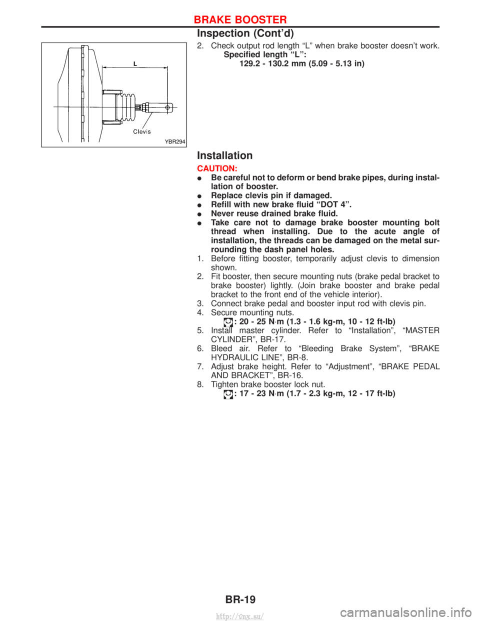
2. Check output rod length ªLº when brake booster doesn't work.Specified length ªLº:129.2 - 130.2 mm (5.09 - 5.13 in)
Installation
CAUTION:
IBe careful not to deform or bend brake pipes, during instal-
lation of booster.
I Replace clevis pin if damaged.
I Refill with new brake fluid ªDOT 4º.
I Never reuse drained brake fluid.
I Take care not to damage brake booster mounting bolt
thread when installing. Due to the acute angle of
installation, the threads can be damaged on the metal sur-
rounding the dash panel holes.
1. Before fitting booster, temporarily adjust clevis to dimension shown.
2. Fit booster, then secure mounting nuts (brake pedal bracket to brake booster) lightly. (Join brake booster and brake pedal
bracket to the front end of the vehicle interior).
3. Connect brake pedal and booster input rod with clevis pin.
4. Secure mounting nuts.
:20-25N ×m (1.3 - 1.6 kg-m, 10 - 12 ft-lb)
5. Install master cylinder. Refer to ªInstallationº, ªMASTER CYLINDERº, BR-17.
6. Bleed air. Refer to ªBleeding Brake Systemº, ªBRAKE HYDRAULIC LINEº, BR-8.
7. Adjust brake height. Refer to ªAdjustmentº, ªBRAKE PEDAL AND BRACKETº, BR-16.
8. Tighten brake booster lock nut.
:17-23N ×m (1.7 - 2.3 kg-m, 12 - 17 ft-lb)
YBR294
BRAKE BOOSTER
Inspection (Cont'd)
BR-19
http://vnx.su/