spare tire NISSAN TERRANO 2004 Service Repair Manual
[x] Cancel search | Manufacturer: NISSAN, Model Year: 2004, Model line: TERRANO, Model: NISSAN TERRANO 2004Pages: 1833, PDF Size: 53.42 MB
Page 33 of 1833
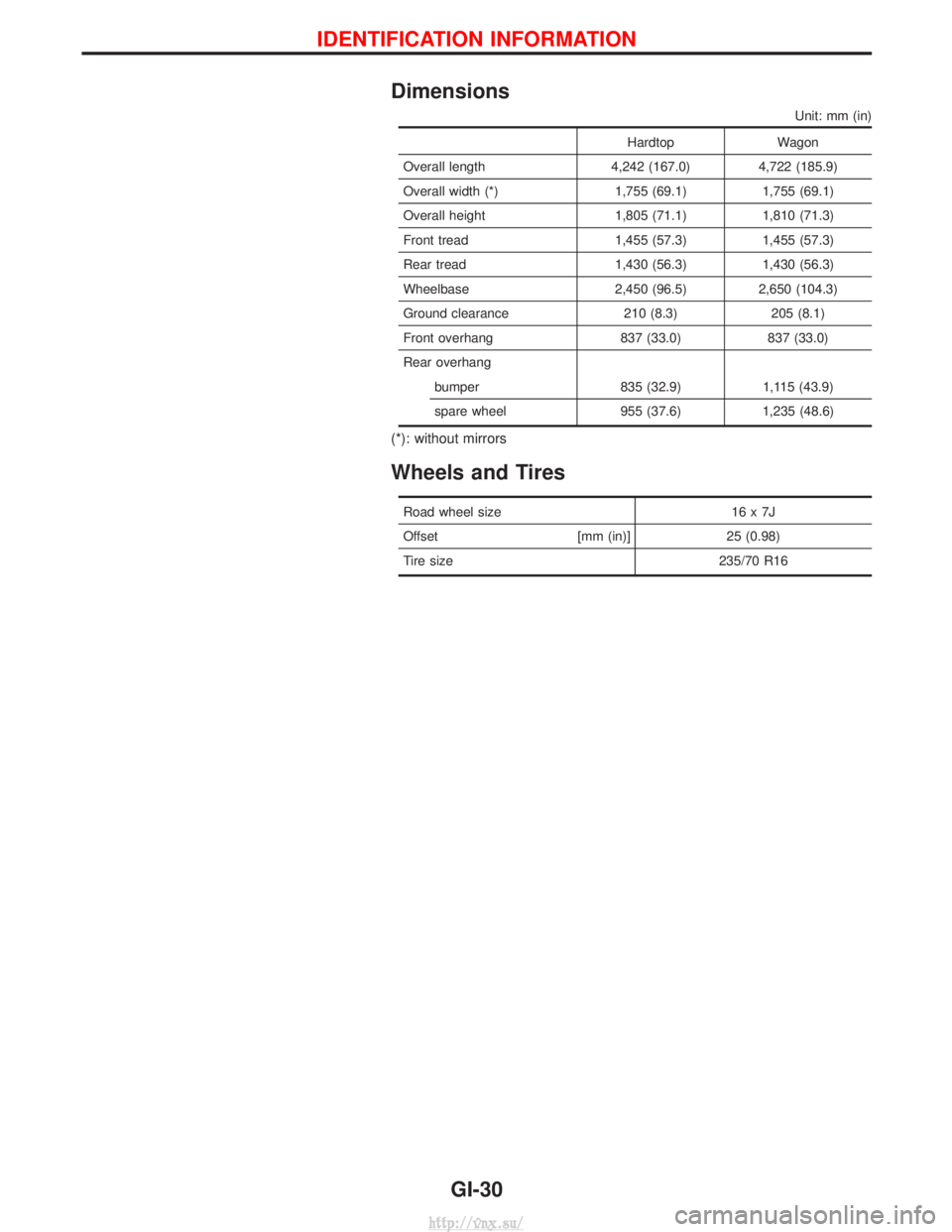
Dimensions
Unit: mm (in)
HardtopWagon
Overall length 4,242 (167.0) 4,722 (185.9)
Overall width (*) 1,755 (69.1) 1,755 (69.1)
Overall height 1,805 (71.1) 1,810 (71.3)
Front tread 1,455 (57.3) 1,455 (57.3)
Rear tread 1,430 (56.3) 1,430 (56.3)
Wheelbase 2,450 (96.5) 2,650 (104.3)
Ground clearance 210 (8.3) 205 (8.1)
Front overhang 837 (33.0) 837 (33.0)
Rear overhang bumper 835 (32.9) 1,115 (43.9)
spare wheel 955 (37.6) 1,235 (48.6)
(*): without mirrors
Wheels and Tires
Road wheel size 16 x 7J
Offset [mm (in)]25 (0.98)
Tire size 235/70 R16
IDENTIFICATION INFORMATION
GI-30
http://vnx.su/
Page 44 of 1833
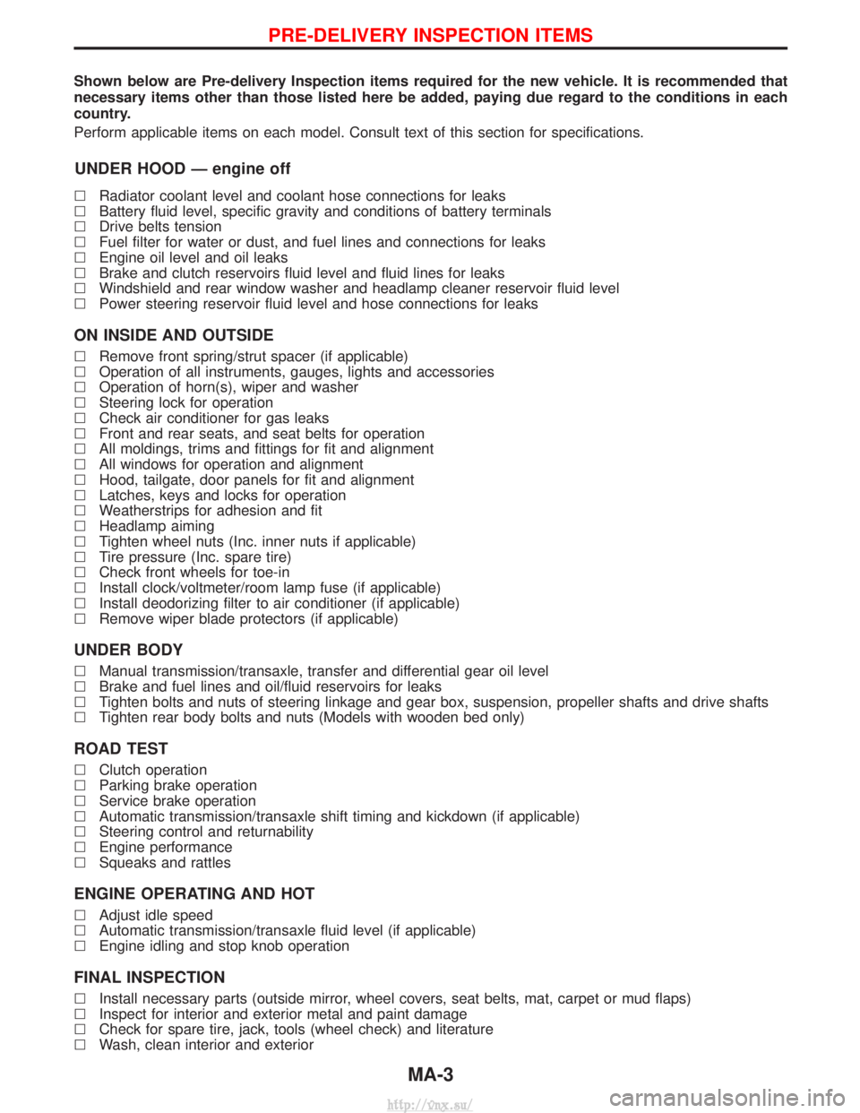
Shown below are Pre-delivery Inspection items required for the new vehicle. It is recommended that
necessary items other than those listed here be added, paying due regard to the conditions in each
country.
Perform applicable items on each model. Consult text of this section for specifications.
UNDER HOOD Ð engine off
lRadiator coolant level and coolant hose connections for leaks
l Battery fluid level, specific gravity and conditions of battery terminals
l Drive belts tension
l Fuel filter for water or dust, and fuel lines and connections for leaks
l Engine oil level and oil leaks
l Brake and clutch reservoirs fluid level and fluid lines for leaks
l Windshield and rear window washer and headlamp cleaner reservoir fluid level
l Power steering reservoir fluid level and hose connections for leaks
ON INSIDE AND OUTSIDE
lRemove front spring/strut spacer (if applicable)
l Operation of all instruments, gauges, lights and accessories
l Operation of horn(s), wiper and washer
l Steering lock for operation
l Check air conditioner for gas leaks
l Front and rear seats, and seat belts for operation
l All moldings, trims and fittings for fit and alignment
l All windows for operation and alignment
l Hood, tailgate, door panels for fit and alignment
l Latches, keys and locks for operation
l Weatherstrips for adhesion and fit
l Headlamp aiming
l Tighten wheel nuts (Inc. inner nuts if applicable)
l Tire pressure (Inc. spare tire)
l Check front wheels for toe-in
l Install clock/voltmeter/room lamp fuse (if applicable)
l Install deodorizing filter to air conditioner (if applicable)
l Remove wiper blade protectors (if applicable)
UNDER BODY
lManual transmission/transaxle, transfer and differential gear oil level
l Brake and fuel lines and oil/fluid reservoirs for leaks
l Tighten bolts and nuts of steering linkage and gear box, suspension, propeller shafts and drive shafts
l Tighten rear body bolts and nuts (Models with wooden bed only)
ROAD TEST
lClutch operation
l Parking brake operation
l Service brake operation
l Automatic transmission/transaxle shift timing and kickdown (if applicable)
l Steering control and returnability
l Engine performance
l Squeaks and rattles
ENGINE OPERATING AND HOT
lAdjust idle speed
l Automatic transmission/transaxle fluid level (if applicable)
l Engine idling and stop knob operation
FINAL INSPECTION
lInstall necessary parts (outside mirror, wheel covers, seat belts, mat, carpet or mud flaps)
l Inspect for interior and exterior metal and paint damage
l Check for spare tire, jack, tools (wheel check) and literature
l Wash, clean interior and exterior
PRE-DELIVERY INSPECTION ITEMS
MA-3
http://vnx.su/
Page 45 of 1833
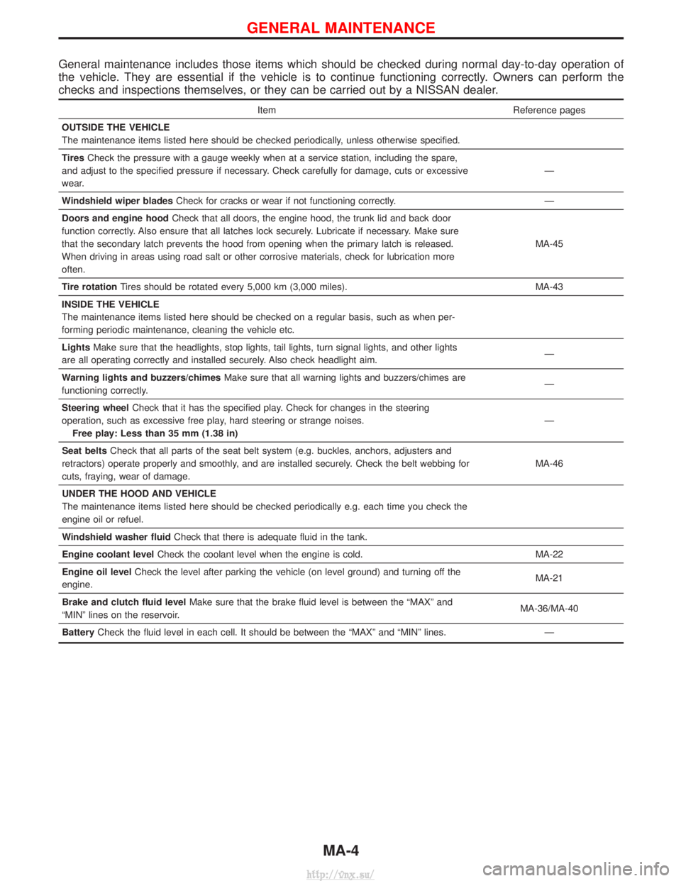
General maintenance includes those items which should be checked during normal day-to-day operation of
the vehicle. They are essential if the vehicle is to continue functioning correctly. Owners can perform the
checks and inspections themselves, or they can be carried out by a NISSAN dealer.
ItemReference pages
OUTSIDE THE VEHICLE
The maintenance items listed here should be checked periodically, unless otherwise specified.
Tires Check the pressure with a gauge weekly when at a service station, including the spare,
and adjust to the specified pressure if necessary. Check carefully for damage, cuts or excessive
wear. Ð
Windshield wiper blades Check for cracks or wear if not functioning correctly. Ð
Doors and engine hood Check that all doors, the engine hood, the trunk lid and back door
function correctly. Also ensure that all latches lock securely. Lubricate if necessary. Make sure
that the secondary latch prevents the hood from opening when the primary latch is released.
When driving in areas using road salt or other corrosive materials, check for lubrication more
often. MA-45
Tire rotation Tires should be rotated every 5,000 km (3,000 miles). MA-43
INSIDE THE VEHICLE
The maintenance items listed here should be checked on a regular basis, such as when per-
forming periodic maintenance, cleaning the vehicle etc.
Lights Make sure that the headlights, stop lights, tail lights, turn signal lights, and other lights
are all operating correctly and installed securely. Also check headlight aim. Ð
Warning lights and buzzers/chimes Make sure that all warning lights and buzzers/chimes are
functioning correctly. Ð
Steering wheel Check that it has the specified play. Check for changes in the steering
operation, such as excessive free play, hard steering or strange noises. Free play: Less than 35 mm (1.38 in) Ð
Seat belts Check that all parts of the seat belt system (e.g. buckles, anchors, adjusters and
retractors) operate properly and smoothly, and are installed securely. Check the belt webbing for
cuts, fraying, wear of damage. MA-46
UNDER THE HOOD AND VEHICLE
The maintenance items listed here should be checked periodically e.g. each time you check the
engine oil or refuel.
Windshield washer fluid Check that there is adequate fluid in the tank.
Engine coolant level Check the coolant level when the engine is cold. MA-22
Engine oil level Check the level after parking the vehicle (on level ground) and turning off the
engine. MA-21
Brake and clutch fluid level Make sure that the brake fluid level is between the ªMAXº and
ªMINº lines on the reservoir. MA-36/MA-40
Battery Check the fluid level in each cell. It should be between the ªMAXº and ªMINº lines. Ð
GENERAL MAINTENANCE
MA-4
http://vnx.su/
Page 90 of 1833
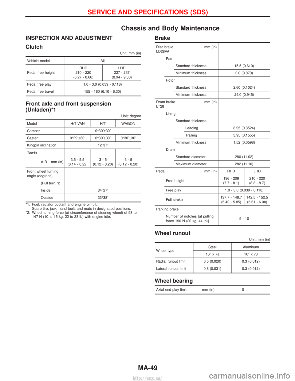
Chassis and Body Maintenance
INSPECTION AND ADJUSTMENT
Clutch
Unit: mm (in)
Vehicle modelAll
Pedal free height RHD
210 - 220
(8.27 - 8.66) LHD
227 - 237
(8.94 - 9.33)
Pedal free play 1.0 - 3.0 (0.039 - 0.118)
Pedal free travel 155 - 160 (6.10 - 6.30)
Front axle and front suspension
(Unladen)*1
Unit: degree
Model H/T VAN H/T WAGON
Camber 0É30¢ 30¢
Caster 0É29¢ 30¢ 0É30¢ 30¢ 0É30¢ 30¢
Kingpin inclination 12É37¢
Toe-in
A-B mm (in) 3.5 - 5.5
(0.14 - 0.22) 3-5
(0.12 - 0.20) 3-5
(0.12 - 0.20)
Front wheel turning
angle (degrees) (Full turn)*2
Inside 34É27¢
Outside 33É38¢
*1: Fuel, radiator coolant and engine oil full. Spare tire, jack, hand tools and mats in designated positions.
*2: Wheel turning force (at circumference of steering wheel) of 98 to 147 N (10 to 15 kg, 22 to 33 lb) with engine idle.
Brake
Disc brake mm (in)
LD28VA
PadStandard thickness 15.5 (0.610)
Minimum thickness 2.0 (0.079)
Rotor Standard thickness 2.60 (0.1024)
Minimum thickness 24.0 (0.945)
Drum brake mm (in)
LT28 LiningStandard thicknessLeading 8.95 (0.3524)
Trailing 3.95 (0.1555)
Minimum thickness 1.52 (0.0598)
Drum Standard diameter 280 (11.02)
Maximum diameter 282 (11.10)
Pedal mm (in) RHD LHD
Free height 196 - 206
(7.7 - 8.1) 210 - 220
(8.3 - 8.7)
Free play 1.0 - 3.0 (0.039 - 0.118)
Full stroke 137.7 - 148.7
(5.42 - 5.85) 142.5 - 152.5
(5.61 - 6.00)
Parking brake Number of notches [at pulling
force 196 N (20 kg, 44 lb)] 9-10
Wheel runout
Unit: mm (in)
Wheel typeSteel Aluminum
16² x7J 16 ²x7J
Radial runout limit 0.5 (0.020) 0.3 (0.012)
Lateral runout limit 0.8 (0.031) 0.3 (0.012)
Wheel bearing
Axial end play limit mm (in) 0
SERVICE AND SPECIFICATIONS (SDS)
MA-49
http://vnx.su/
Page 1113 of 1833
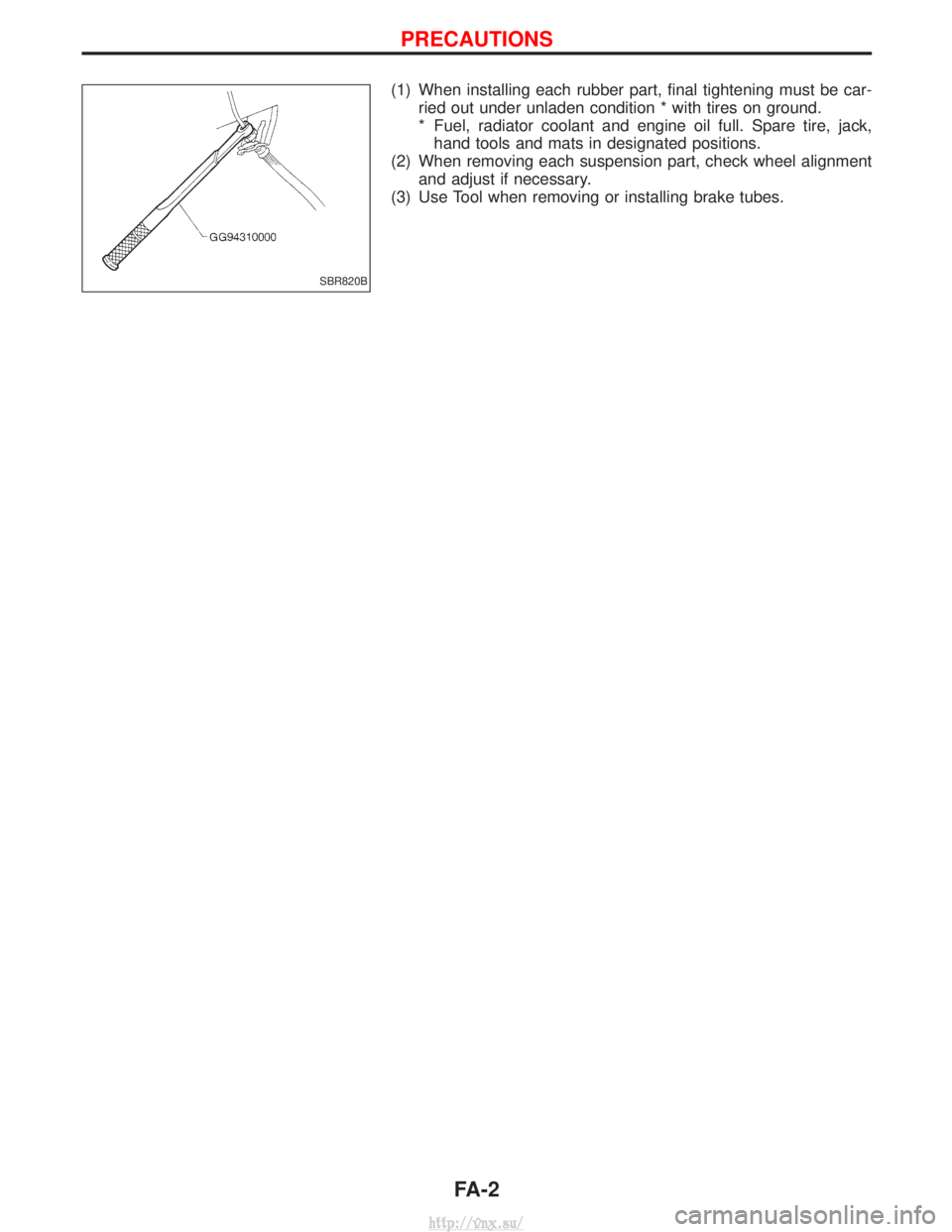
(1) When installing each rubber part, final tightening must be car-ried out under unladen condition * with tires on ground.
* Fuel, radiator coolant and engine oil full. Spare tire, jack,hand tools and mats in designated positions.
(2) When removing each suspension part, check wheel alignment and adjust if necessary.
(3) Use Tool when removing or installing brake tubes.
SBR820B
PRECAUTIONS
FA-2
http://vnx.su/
Page 1150 of 1833
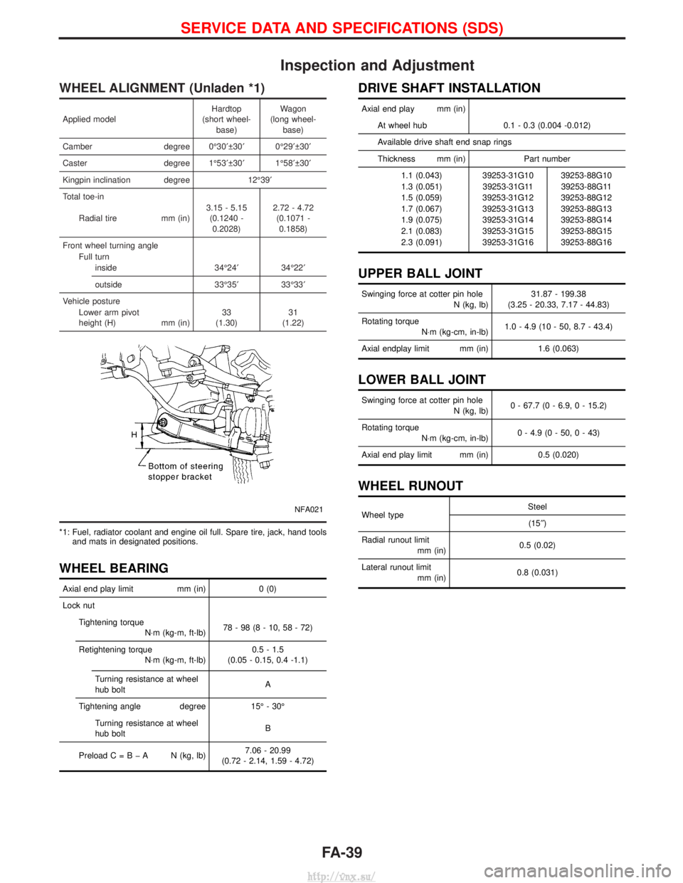
Inspection and Adjustment
WHEEL ALIGNMENT (Unladen *1)
Applied modelHardtop
(short wheel- base) Wagon
(long wheel- base)
Camber degree 0É30¢ 30¢0É29¢ 30¢
Caster degree 1É53¢ 30¢1É58¢ 30¢
Kingpin inclination degree 12É39¢
Total toe-in
Radial tire mm (in)3.15 - 5.15
(0.1240 -0.2028) 2.72 - 4.72
(0.1071 -0.1858)
Front wheel turning angle Full turninside 34É24¢34É22¢
outside 33É35¢33É33¢
Vehicle posture Lower arm pivot
height (H) mm (in)33
(1.30) 31
(1.22)
NFA021
*1: Fuel, radiator coolant and engine oil full. Spare tire, jack, hand tools and mats in designated positions.
WHEEL BEARING
Axial end play limit mm (in)0 (0)
Lock nut Tightening torque N×m (kg-m, ft-lb) 78-98(8-10,58-72)
Retightening torque N×m (kg-m, ft-lb) 0.5 - 1.5
(0.05 - 0.15, 0.4 -1.1)
Turning resistance at wheel
hub bolt A
Tightening angle degree 15É - 30É
Turning resistance at wheel
hub bolt B
PreloadC=BþA N(kg, lb) 7.06 - 20.99
(0.72 - 2.14, 1.59 - 4.72)
DRIVE SHAFT INSTALLATION
Axial end play mm (in)
At wheel hub 0.1 - 0.3 (0.004 -0.012)
Available drive shaft end snap rings
Thickness mm (in) Part number 1.1 (0.043) 39253-31G10 39253-88G10
1.3 (0.051) 39253-31G11 39253-88G11
1.5 (0.059) 39253-31G12 39253-88G12
1.7 (0.067) 39253-31G13 39253-88G13
1.9 (0.075) 39253-31G14 39253-88G14
2.1 (0.083) 39253-31G15 39253-88G15
2.3 (0.091) 39253-31G16 39253-88G16
UPPER BALL JOINT
Swinging force at cotter pin hole N (kg, lb)31.87 - 199.38
(3.25 - 20.33, 7.17 - 44.83)
Rotating torque N×m (kg-cm, in-lb) 1.0 - 4.9 (10 - 50, 8.7 - 43.4)
Axial endplay limit mm (in) 1.6 (0.063)
LOWER BALL JOINT
Swinging force at cotter pin hole
N (kg, lb)0 - 67.7 (0 - 6.9, 0 - 15.2)
Rotating torque N×m (kg-cm, in-lb) 0 - 4.9 (0 - 50, 0 - 43)
Axial end play limit mm (in) 0.5 (0.020)
WHEEL RUNOUT
Wheel type Steel
(15² )
Radial runout limit mm (in) 0.5 (0.02)
Lateral runout limit mm (in) 0.8 (0.031)
SERVICE DATA AND SPECIFICATIONS (SDS)
FA-39
http://vnx.su/
Page 1153 of 1833
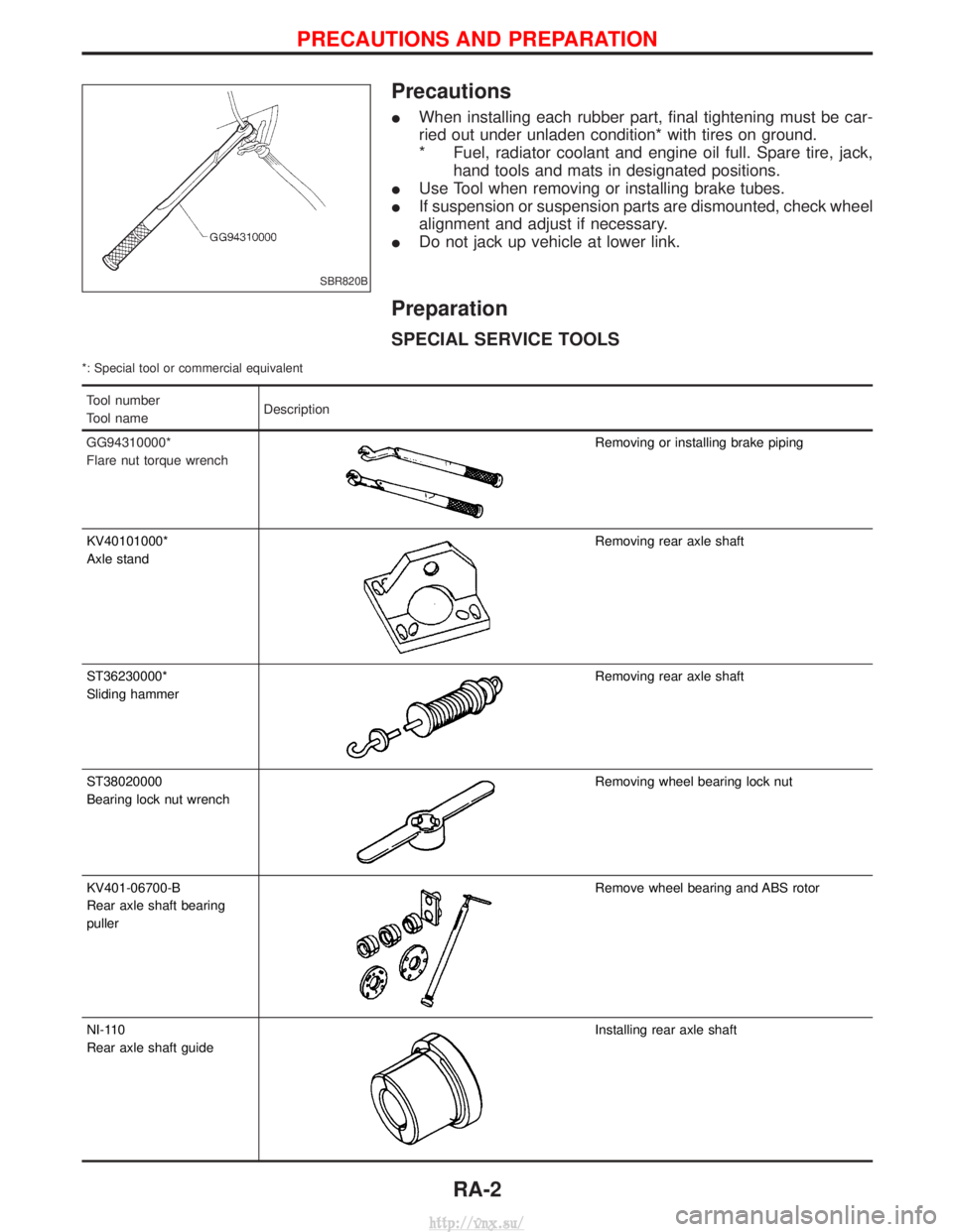
Precautions
IWhen installing each rubber part, final tightening must be car-
ried out under unladen condition* with tires on ground.
* Fuel, radiator coolant and engine oil full. Spare tire, jack,
hand tools and mats in designated positions.
I Use Tool when removing or installing brake tubes.
I If suspension or suspension parts are dismounted, check wheel
alignment and adjust if necessary.
I Do not jack up vehicle at lower link.
Preparation
SPECIAL SERVICE TOOLS
*: Special tool or commercial equivalent
Tool number
Tool name Description
GG94310000*
Flare nut torque wrench
Removing or installing brake piping
KV40101000*
Axle stand
Removing rear axle shaft
ST36230000*
Sliding hammer
Removing rear axle shaft
ST38020000
Bearing lock nut wrench
Removing wheel bearing lock nut
KV401-06700-B
Rear axle shaft bearing
puller
Remove wheel bearing and ABS rotor
NI-110
Rear axle shaft guide
Installing rear axle shaft
SBR820B
PRECAUTIONS AND PREPARATION
RA-2
http://vnx.su/
Page 1180 of 1833
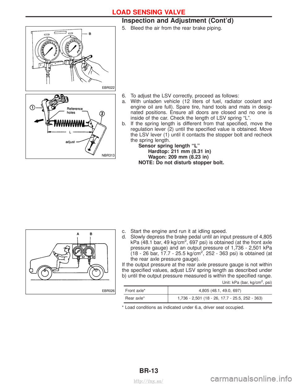
5. Bleed the air from the rear brake piping.
6. To adjust the LSV correctly, proceed as follows:
a. With unladen vehicle (12 liters of fuel, radiator coolant andengine oil are full). Spare tire, hand tools and mats in desig-
nated positions. Ensure all doors are closed and no one is
inside of the car. Check the length of LSV spring ªLº.
b. If the spring length is different from that specified, move the regulation lever (2) until the specified value is obtained. Move
the LSV lever (1) until it contacts the stopper bolt and recheck
the spring length.Sensor spring length ªLº Hardtop: 211 mm (8.31 in)
Wagon: 209 mm (8.23 in)
NOTE: Do not disturb stopper bolt.
c. Start the engine and run it at idling speed.
d. Slowly depress the brake pedal until an input pressure of 4,805 kPa (48.1 bar, 49 kg/cm
2, 697 psi) is obtained (at the front axle
pressure gauge) and an output pressure of 1,736 - 2,501 kPa
(18 - 26 bar, 17.7 - 25.5 kg/cm
2, 252 - 363 psi) is obtained (at
the rear axle pressure gauge).
If the output pressure at the rear axle pressure gauge is not within
the specified values, adjust LSV spring length as described under
b) until the output pressure measured is within the specified range.
Unit: kPa (bar, kg/cm2, psi)
Front axle* 4,805 (48.1, 49.0, 697)
Rear axle* 1,736 - 2,501 (18 - 26, 17.7 - 25.5, 252 - 363)
* Load conditions as indicated under 6.a, driver seat occupied.
EBR022
NBR313
EBR026
LOAD SENSING VALVE
Inspection and Adjustment (Cont'd)
BR-13
http://vnx.su/