ecm NISSAN TERRANO 2004 Service Repair Manual
[x] Cancel search | Manufacturer: NISSAN, Model Year: 2004, Model line: TERRANO, Model: NISSAN TERRANO 2004Pages: 1833, PDF Size: 53.42 MB
Page 8 of 1833
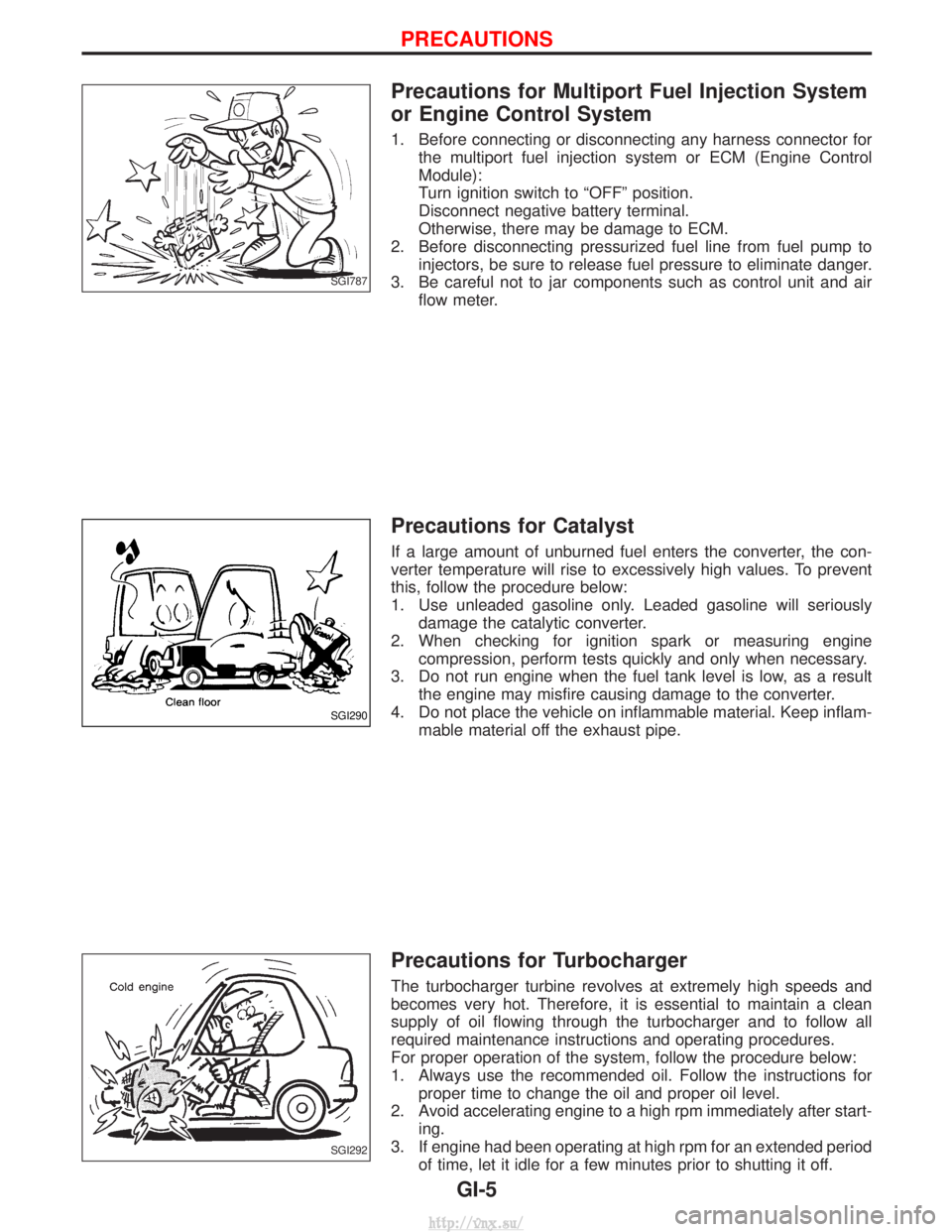
Precautions for Multiport Fuel Injection System
or Engine Control System
1. Before connecting or disconnecting any harness connector forthe multiport fuel injection system or ECM (Engine Control
Module):
Turn ignition switch to ªOFFº position.
Disconnect negative battery terminal.
Otherwise, there may be damage to ECM.
2. Before disconnecting pressurized fuel line from fuel pump to injectors, be sure to release fuel pressure to eliminate danger.
3. Be careful not to jar components such as control unit and air flow meter.
Precautions for Catalyst
If a large amount of unburned fuel enters the converter, the con-
verter temperature will rise to excessively high values. To prevent
this, follow the procedure below:
1. Use unleaded gasoline only. Leaded gasoline will seriouslydamage the catalytic converter.
2. When checking for ignition spark or measuring engine compression, perform tests quickly and only when necessary.
3. Do not run engine when the fuel tank level is low, as a result the engine may misfire causing damage to the converter.
4. Do not place the vehicle on inflammable material. Keep inflam- mable material off the exhaust pipe.
Precautions for Turbocharger
The turbocharger turbine revolves at extremely high speeds and
becomes very hot. Therefore, it is essential to maintain a clean
supply of oil flowing through the turbocharger and to follow all
required maintenance instructions and operating procedures.
For proper operation of the system, follow the procedure below:
1. Always use the recommended oil. Follow the instructions forproper time to change the oil and proper oil level.
2. Avoid accelerating engine to a high rpm immediately after start- ing.
3. If engine had been operating at high rpm for an extended period of time, let it idle for a few minutes prior to shutting it off.
SGI787
SGI290
SGI292
PRECAUTIONS
GI-5
http://vnx.su/
Page 19 of 1833
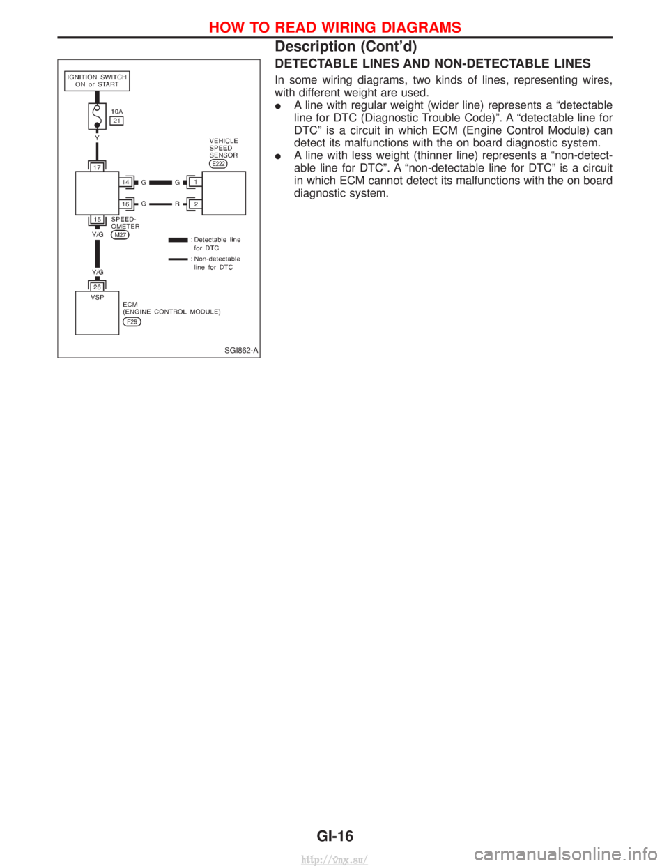
DETECTABLE LINES AND NON-DETECTABLE LINES
In some wiring diagrams, two kinds of lines, representing wires,
with different weight are used.
IA line with regular weight (wider line) represents a ªdetectable
line for DTC (Diagnostic Trouble Code)º. A ªdetectable line for
DTCº is a circuit in which ECM (Engine Control Module) can
detect its malfunctions with the on board diagnostic system.
I A line with less weight (thinner line) represents a ªnon-detect-
able line for DTCº. A ªnon-detectable line for DTCº is a circuit
in which ECM cannot detect its malfunctions with the on board
diagnostic system.
SGI862-A
HOW TO READ WIRING DIAGRAMS
Description (Cont'd)
GI-16
http://vnx.su/
Page 22 of 1833
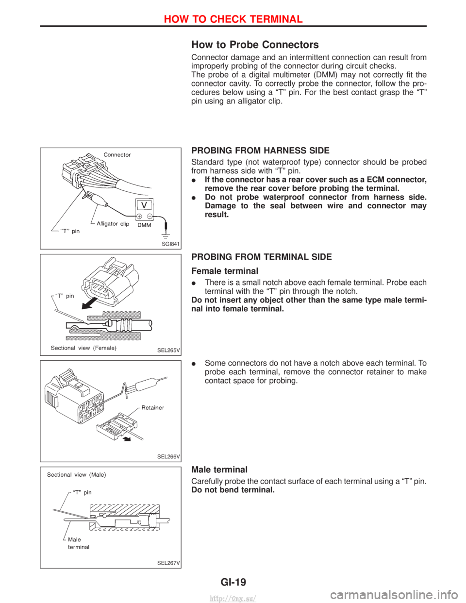
How to Probe Connectors
Connector damage and an intermittent connection can result from
improperly probing of the connector during circuit checks.
The probe of a digital multimeter (DMM) may not correctly fit the
connector cavity. To correctly probe the connector, follow the pro-
cedures below using a ªTº pin. For the best contact grasp the ªTº
pin using an alligator clip.
PROBING FROM HARNESS SIDE
Standard type (not waterproof type) connector should be probed
from harness side with ªTº pin.
IIf the connector has a rear cover such as a ECM connector,
remove the rear cover before probing the terminal.
I Do not probe waterproof connector from harness side.
Damage to the seal between wire and connector may
result.
PROBING FROM TERMINAL SIDE
Female terminal
IThere is a small notch above each female terminal. Probe each
terminal with the ªTº pin through the notch.
Do not insert any object other than the same type male termi-
nal into female terminal.
I Some connectors do not have a notch above each terminal. To
probe each terminal, remove the connector retainer to make
contact space for probing.
Male terminal
Carefully probe the contact surface of each terminal using a ªTº pin.
Do not bend terminal.
SGI841
SEL265V
SEL266V
SEL267V
HOW TO CHECK TERMINAL
GI-19
http://vnx.su/
Page 28 of 1833
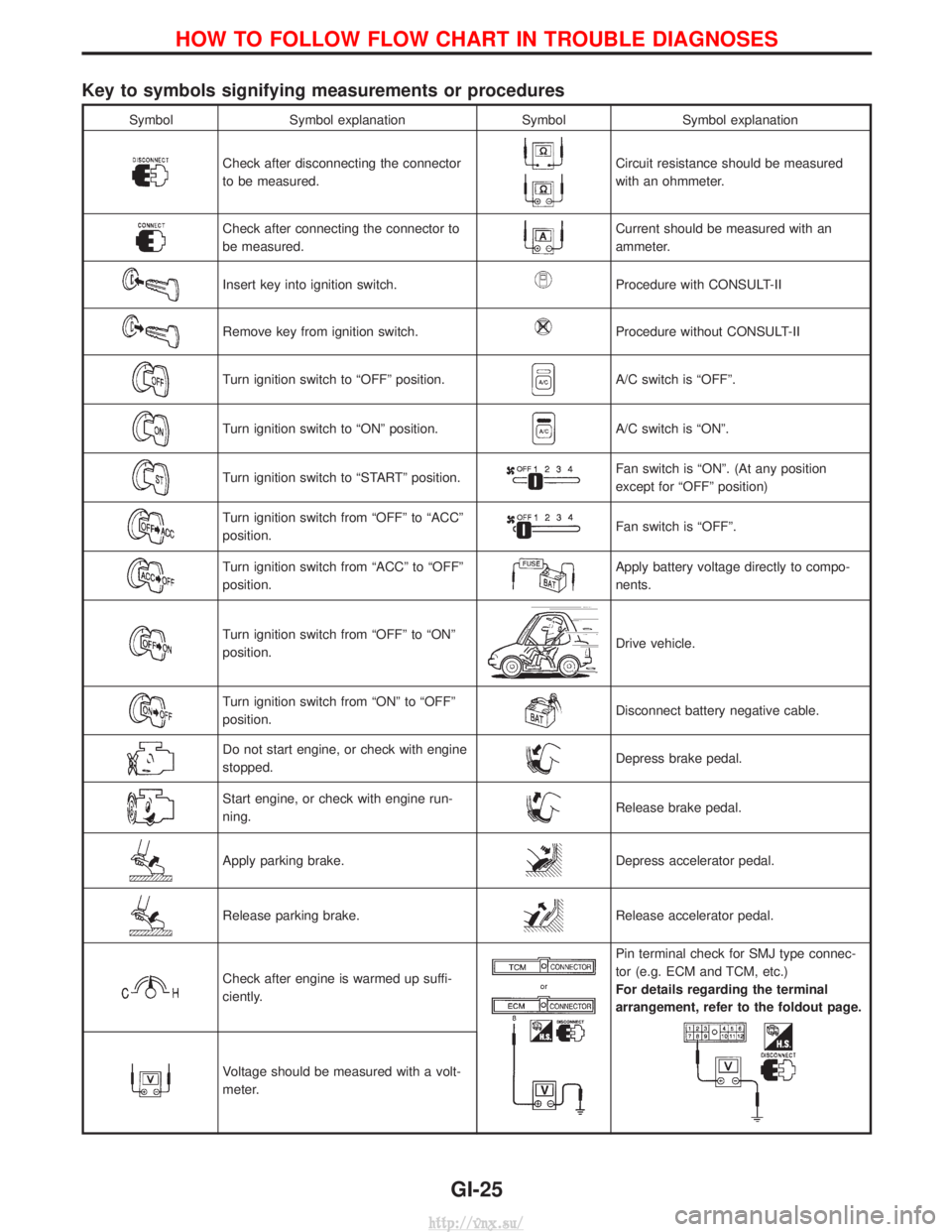
Key to symbols signifying measurements or procedures
SymbolSymbol explanation SymbolSymbol explanation
Check after disconnecting the connector
to be measured.Circuit resistance should be measured
with an ohmmeter.
Check after connecting the connector to
be measured.Current should be measured with an
ammeter.
Insert key into ignition switch.Procedure with CONSULT-II
Remove key from ignition switch.Procedure without CONSULT-II
Turn ignition switch to ªOFFº position.A/C switch is ªOFFº.
Turn ignition switch to ªONº position.A/C switch is ªONº.
Turn ignition switch to ªSTARTº position.Fan switch is ªONº. (At any position
except for ªOFFº position)
Turn ignition switch from ªOFFº to ªACCº
position.Fan switch is ªOFFº.
Turn ignition switch from ªACCº to ªOFFº
position.Apply battery voltage directly to compo-
nents.
Turn ignition switch from ªOFFº to ªONº
position.Drive vehicle.
Turn ignition switch from ªONº to ªOFFº
position.Disconnect battery negative cable.
Do not start engine, or check with engine
stopped.Depress brake pedal.
Start engine, or check with engine run-
ning.Release brake pedal.
Apply parking brake.Depress accelerator pedal.
Release parking brake.Release accelerator pedal.
Check after engine is warmed up suffi-
ciently.
Pin terminal check for SMJ type connec-
tor (e.g. ECM and TCM, etc.)
For details regarding the terminal
arrangement, refer to the foldout page.
Voltage should be measured with a volt-
meter.
HOW TO FOLLOW FLOW CHART IN TROUBLE DIAGNOSES
GI-25
http://vnx.su/
Page 29 of 1833
Function and System Application
Diagnostictest mode Function ENGINE A/T Air bag ABS NATS*1
Self-diagnostic results Self-diagnostic results can be read and erased quickly. xxxxx
ECU discriminated No. Classification number of a replacement ECU can be
read to prevent an incorrect ECU from being installed. ÐÐxÐÐ
Data monitor Input/Output data in the ECM can be read. x xÐxÐ
Active test Diagnostic Test Mode in which CONSULT-II drives
some actuators apart from the ECMs and also shifts
some parameters in a specified range. xÐÐxÐ
ECU (ECM) part number ECU (ECM) part number can be read. x xÐxÐ
Control unit initialisation All registered ignition key IDs in NATS components can
be initialised and new IDs can be registered. ÐÐÐÐ x
Self-function check ECM checks its own NATS communication interface. ÐÐÐÐ x
x: Applicable
*1: NATS: Nissan Anti-Theft System
Nickel Metal Hydride Battery Replacement
CONSULT-II contains a nickel metal hydride battery. When replacing the battery obey the following:
WARNING:
Replace the nickel metal hydride battery with genuine CONSULT-II battery only. Use of another battery
may present a risk of fire or explosion. The battery may present a fire or chemical burn hazard if mis-
treated. Do not recharge, disassemble of dispose of in fire.
Keep the battery out of reach of children and discard used battery conforming to the local regulations.
Checking Equipment
When ordering this equipment, contact your NISSAN distributor.
Tool name Description
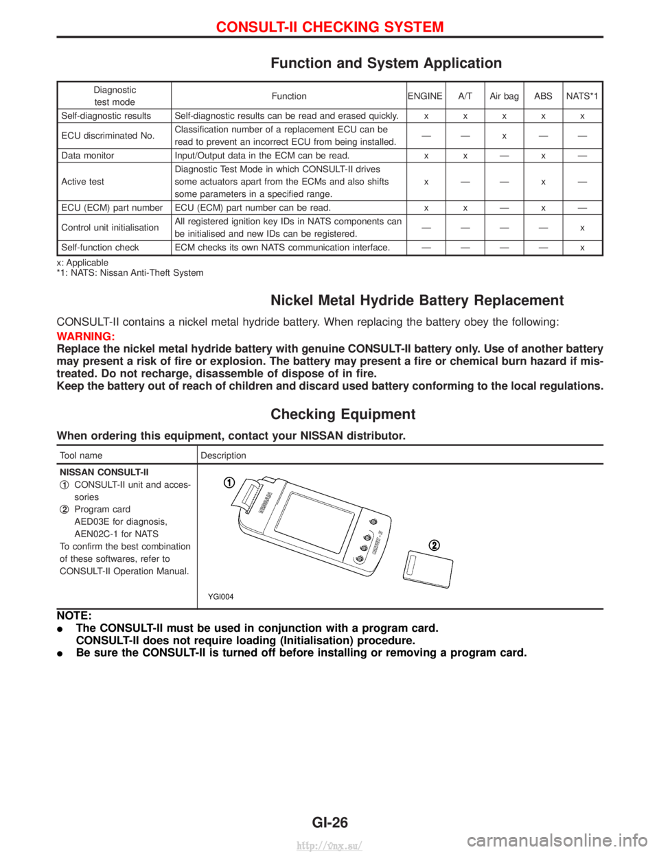
NISSAN CONSULT-II
q
1CONSULT-II unit and acces-
sories
q
2Program card
AED03E for diagnosis,
AEN02C-1 for NATS
To confirm the best combination
of these softwares, refer to
CONSULT-II Operation Manual.
YGI004
NOTE:
I The CONSULT-II must be used in conjunction with a program card.
CONSULT-II does not require loading (Initialisation) procedure.
I Be sure the CONSULT-II is turned off before installing or removing a program card.
CONSULT-II CHECKING SYSTEM
GI-26
http://vnx.su/
Page 37 of 1833
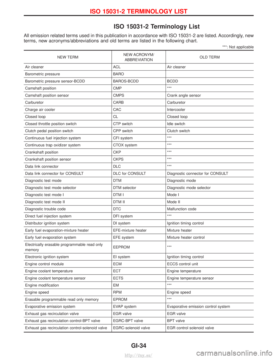
ISO 15031-2 Terminology List
All emission related terms used in this publication in accordance with ISO 15031-2 are listed. Accordingly, new
terms, new acronyms/abbreviations and old terms are listed in the following chart.
***: Not applicable
NEW TERMNEW ACRONYM/
ABBREVIATION OLD TERM
Air cleaner ACL Air cleaner
Barometric pressure BARO
Barometric pressure sensor-BCDD BAROS-BCDD BCDD
Camshaft position CMP ***
Camshaft position sensor CMPS Crank angle sensor
Carburetor CARB Carburetor
Charge air cooler CAC Intercooler
Closed loop CL Closed loop
Closed throttle position switch CTP switch Idle switch
Clutch pedal position switch CPP switch Clutch switch
Continuous fuel injection system CFI system ***
Continuous trap oxidizer system CTOX system ***
Crankshaft position CKP ***
Crankshaft position sensor CKPS ***
Data link connector DLC ***
Data link connector for CONSULT DLC for CONSULT Diagnostic connector for CONSULT
Diagnostic test mode DTM Diagnostic mode
Diagnostic test mode selector DTM selector Diagnostic mode selector
Diagnostic test mode I DTM I Mode I
Diagnostic test mode II DTM II Mode II
Diagnostic trouble code DTC Malfunction code
Direct fuel injection system DFI system ***
Distributor ignition system DI system Ignition timing control
Early fuel evaporation-mixture heater EFE-mixture heater Mixture heater
Early fuel evaporation system EFE system Mixture heater control
Electrically erasable programmable read only
memory EEPROM ***
Electronic ignition system EI system Ignition timing control
Engine control module ECM ECCS control unit
Engine coolant temperature ECT Engine temperature
Engine coolant temperature sensor ECTS Engine temperature sensor
Engine modification EM ***
Engine speed RPM Engine speed
Erasable programmable read only memory EPROM ***
Evaporative emission system EVAP system Evaporative emission control system
Exhaust gas recirculation valve EGR valve EGR valve
Exhaust gas recirculation control-BPT valve EGRC-BPT valve BPT valve
Exhaust gas recirculation control-solenoid valve EGRC-solenoid valve EGR control solenoid valve
ISO 15031-2 TERMINOLOGY LIST
GI-34
http://vnx.su/
Page 108 of 1833
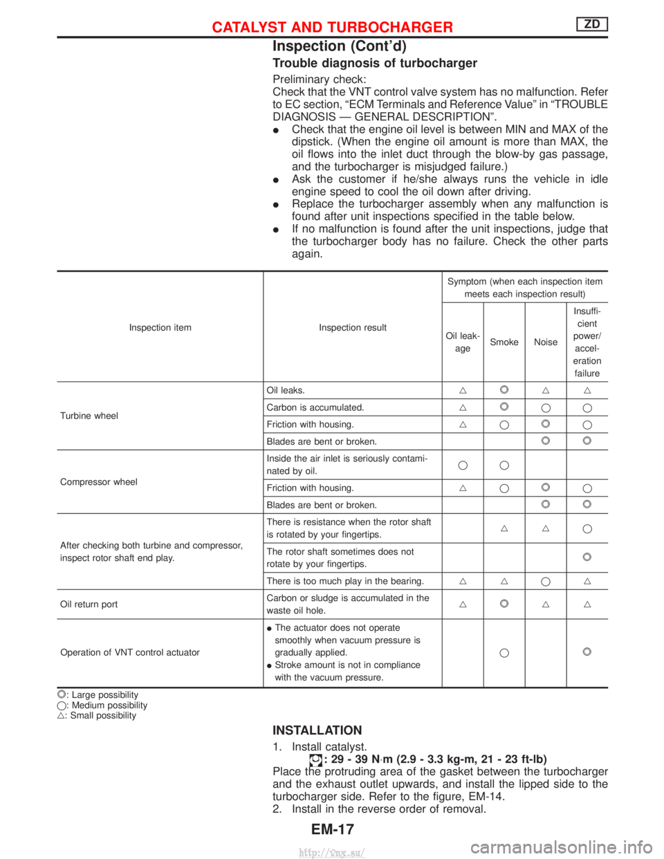
Trouble diagnosis of turbocharger
Preliminary check:
Check that the VNT control valve system has no malfunction. Refer
to EC section, ªECM Terminals and Reference Valueº in ªTROUBLE
DIAGNOSIS Ð GENERAL DESCRIPTIONº.
ICheck that the engine oil level is between MIN and MAX of the
dipstick. (When the engine oil amount is more than MAX, the
oil flows into the inlet duct through the blow-by gas passage,
and the turbocharger is misjudged failure.)
I Ask the customer if he/she always runs the vehicle in idle
engine speed to cool the oil down after driving.
I Replace the turbocharger assembly when any malfunction is
found after unit inspections specified in the table below.
I If no malfunction is found after the unit inspections, judge that
the turbocharger body has no failure. Check the other parts
again.
Inspection item Inspection resultSymptom (when each inspection item
meets each inspection result)
Oil leak- age Smoke Noise Insuffi-
cient
power/ accel-
eration failure
Turbine wheel Oil leaks.
g
gg
Carbon is accumulated. g
qq
Friction with housing. gq
q
Blades are bent or broken.
Compressor wheel Inside the air inlet is seriously contami-
nated by oil.
qq
Friction with housing. gqq
Blades are bent or broken.
After checking both turbine and compressor,
inspect rotor shaft end play. There is resistance when the rotor shaft
is rotated by your fingertips.
ggq
The rotor shaft sometimes does not
rotate by your fingertips.
There is too much play in the bearing. g gqg
Oil return port Carbon or sludge is accumulated in the
waste oil hole.g
gg
Operation of VNT control actuator I
The actuator does not operate
smoothly when vacuum pressure is
gradually applied.
I Stroke amount is not in compliance
with the vacuum pressure. q
: Large possibility
q: Medium possibility
g: Small possibility
INSTALLATION
1. Install catalyst.
:29-39N ×m (2.9 - 3.3 kg-m, 21 - 23 ft-lb)
Place the protruding area of the gasket between the turbocharger
and the exhaust outlet upwards, and install the lipped side to the
turbocharger side. Refer to the figure, EM-14.
2. Install in the reverse order of removal.
CATALYST AND TURBOCHARGERZD
Inspection (Cont'd)
EM-17
http://vnx.su/
Page 276 of 1833
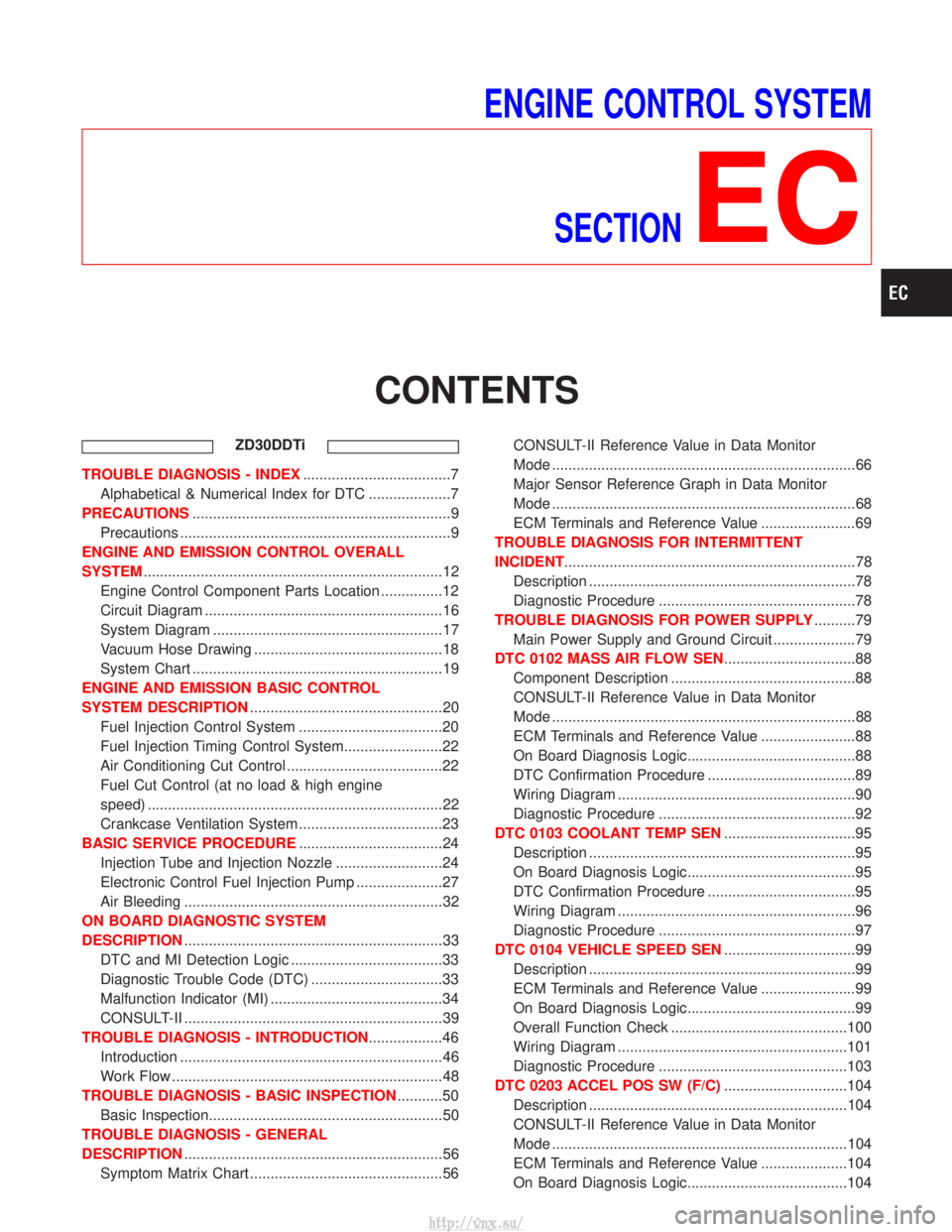
ENGINE CONTROL SYSTEMSECTION
EC
CONTENTS
ZD30DDTi
TROUBLE DIAGNOSIS - INDEX ....................................7
Alphabetical & Numerical Index for DTC ....................7
PRECAUTIONS ...............................................................9
Precautions ..................................................................9
ENGINE AND EMISSION CONTROL OVERALL
SYSTEM ........................................................................\
.12
Engine Control Component Parts Location ...............12
Circuit Diagram ..........................................................16
System Diagram ........................................................17
Vacuum Hose Drawing ..............................................18
System Chart .............................................................19
ENGINE AND EMISSION BASIC CONTROL
SYSTEM DESCRIPTION ...............................................20
Fuel Injection Control System ...................................20
Fuel Injection Timing Control System........................22
Air Conditioning Cut Control ......................................22
Fuel Cut Control (at no load & high engine
speed) ........................................................................\
22
Crankcase Ventilation System ...................................23
BASIC SERVICE PROCEDURE ...................................24
Injection Tube and Injection Nozzle ..........................24
Electronic Control Fuel Injection Pump .....................27
Air Bleeding ...............................................................32
ON BOARD DIAGNOSTIC SYSTEM
DESCRIPTION ...............................................................33
DTC and MI Detection Logic .....................................33
Diagnostic Trouble Code (DTC) ................................33
Malfunction Indicator (MI) ..........................................34
CONSULT-II ...............................................................39
TROUBLE DIAGNOSIS - INTRODUCTION ..................46
Introduction ................................................................46
Work Flow ..................................................................48
TROUBLE DIAGNOSIS - BASIC INSPECTION ...........50
Basic Inspection.........................................................50
TROUBLE DIAGNOSIS - GENERAL
DESCRIPTION ...............................................................56
Symptom Matrix Chart ...............................................56 CONSULT-II Reference Value in Data Monitor
Mode ........................................................................\
..66
Major Sensor Reference Graph in Data Monitor
Mode ........................................................................\
..68
ECM Terminals and Reference Value .......................69
TROUBLE DIAGNOSIS FOR INTERMITTENT
INCIDENT .......................................................................78
Description .................................................................78
Diagnostic Procedure ................................................78
TROUBLE DIAGNOSIS FOR POWER SUPPLY ..........79
Main Power Supply and Ground Circuit ....................79
DTC 0102 MASS AIR FLOW SEN ................................88
Component Description .............................................88
CONSULT-II Reference Value in Data Monitor
Mode ........................................................................\
..88
ECM Terminals and Reference Value .......................88
On Board Diagnosis Logic.........................................88
DTC Confirmation Procedure ....................................89
Wiring Diagram ..........................................................90
Diagnostic Procedure ................................................92
DTC 0103 COOLANT TEMP SEN ................................95
Description .................................................................95
On Board Diagnosis Logic.........................................95
DTC Confirmation Procedure ....................................95
Wiring Diagram ..........................................................96
Diagnostic Procedure ................................................97
DTC 0104 VEHICLE SPEED SEN ................................99
Description .................................................................99
ECM Terminals and Reference Value .......................99
On Board Diagnosis Logic.........................................99
Overall Function Check ...........................................100
Wiring Diagram ........................................................101
Diagnostic Procedure ..............................................103
DTC 0203 ACCEL POS SW (F/C) ..............................104
Description ...............................................................104
CONSULT-II Reference Value in Data Monitor
Mode ........................................................................\
104
ECM Terminals and Reference Value .....................104
On Board Diagnosis Logic.......................................104
http://vnx.su/
Page 277 of 1833
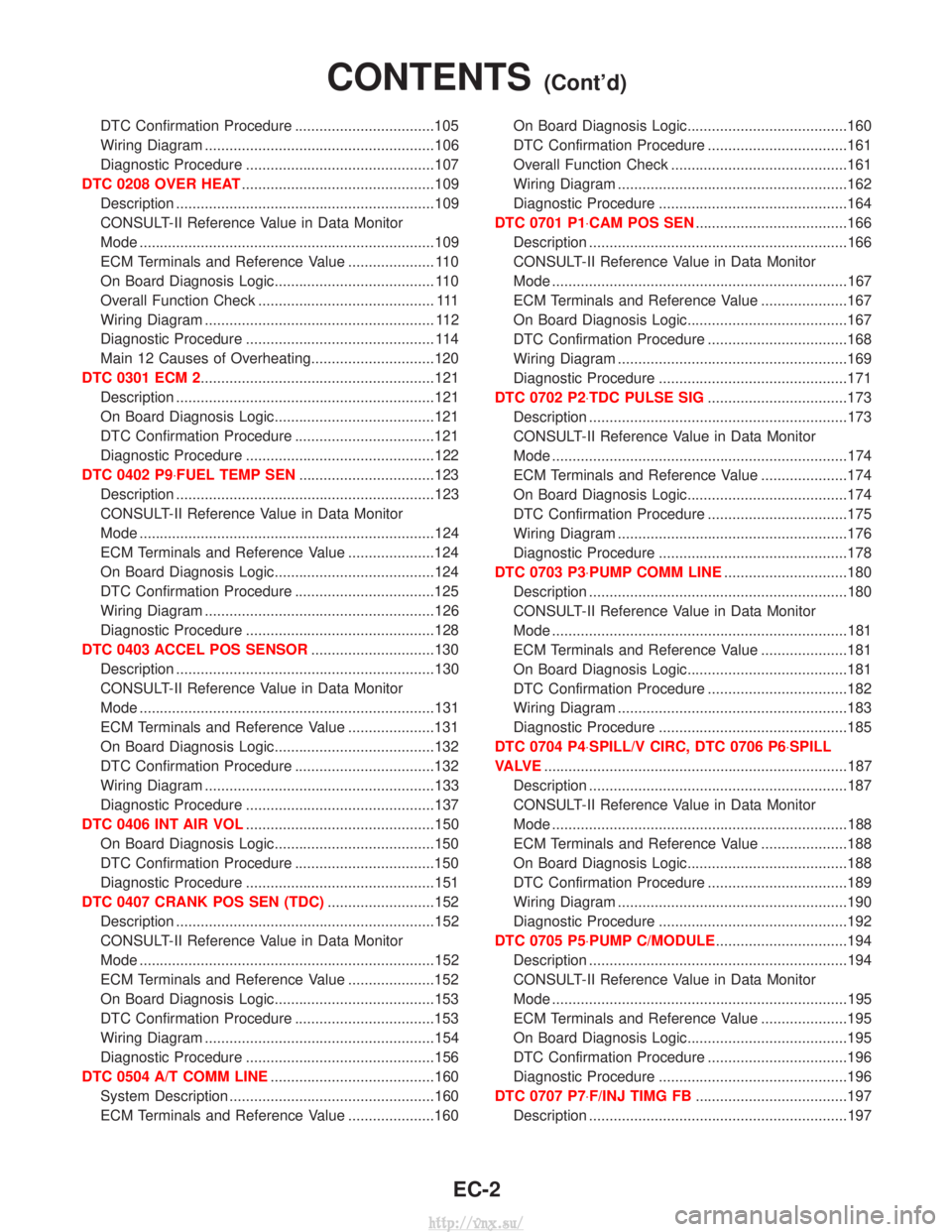
DTC Confirmation Procedure ..................................105
Wiring Diagram ........................................................106
Diagnostic Procedure ..............................................107
DTC 0208 OVER HEAT ...............................................109
Description ...............................................................109
CONSULT-II Reference Value in Data Monitor
Mode ........................................................................\
109
ECM Terminals and Reference Value ..................... 110
On Board Diagnosis Logic....................................... 110
Overall Function Check ........................................... 111
Wiring Diagram ........................................................ 112
Diagnostic Procedure .............................................. 114
Main 12 Causes of Overheating..............................120
DTC 0301 ECM 2.........................................................121 Description ...............................................................121
On Board Diagnosis Logic.......................................121
DTC Confirmation Procedure ..................................121
Diagnostic Procedure ..............................................122
DTC 0402 P9×FUEL TEMP SEN .................................123
Description ...............................................................123
CONSULT-II Reference Value in Data Monitor
Mode ........................................................................\
124
ECM Terminals and Reference Value .....................124
On Board Diagnosis Logic.......................................124
DTC Confirmation Procedure ..................................125
Wiring Diagram ........................................................126
Diagnostic Procedure ..............................................128
DTC 0403 ACCEL POS SENSOR ..............................130
Description ...............................................................130
CONSULT-II Reference Value in Data Monitor
Mode ........................................................................\
131
ECM Terminals and Reference Value .....................131
On Board Diagnosis Logic.......................................132
DTC Confirmation Procedure ..................................132
Wiring Diagram ........................................................133
Diagnostic Procedure ..............................................137
DTC 0406 INT AIR VOL ..............................................150
On Board Diagnosis Logic.......................................150
DTC Confirmation Procedure ..................................150
Diagnostic Procedure ..............................................151
DTC 0407 CRANK POS SEN (TDC) ..........................152
Description ...............................................................152
CONSULT-II Reference Value in Data Monitor
Mode ........................................................................\
152
ECM Terminals and Reference Value .....................152
On Board Diagnosis Logic.......................................153
DTC Confirmation Procedure ..................................153
Wiring Diagram ........................................................154
Diagnostic Procedure ..............................................156
DTC 0504 A/T COMM LINE ........................................160
System Description ..................................................160
ECM Terminals and Reference Value .....................160 On Board Diagnosis Logic.......................................160
DTC Confirmation Procedure ..................................161
Overall Function Check ...........................................161
Wiring Diagram ........................................................162
Diagnostic Procedure ..............................................164
DTC 0701 P1×CAM POS SEN .....................................166
Description ...............................................................166
CONSULT-II Reference Value in Data Monitor
Mode ........................................................................\
167
ECM Terminals and Reference Value .....................167
On Board Diagnosis Logic.......................................167
DTC Confirmation Procedure ..................................168
Wiring Diagram ........................................................169
Diagnostic Procedure ..............................................171
DTC 0702 P2×TDC PULSE SIG ..................................173
Description ...............................................................173
CONSULT-II Reference Value in Data Monitor
Mode ........................................................................\
174
ECM Terminals and Reference Value .....................174
On Board Diagnosis Logic.......................................174
DTC Confirmation Procedure ..................................175
Wiring Diagram ........................................................176
Diagnostic Procedure ..............................................178
DTC 0703 P3×PUMP COMM LINE ..............................180
Description ...............................................................180
CONSULT-II Reference Value in Data Monitor
Mode ........................................................................\
181
ECM Terminals and Reference Value .....................181
On Board Diagnosis Logic.......................................181
DTC Confirmation Procedure ..................................182
Wiring Diagram ........................................................183
Diagnostic Procedure ..............................................185
DTC 0704 P4×SPILL/V CIRC, DTC 0706 P6×SPILL
VA LV E ........................................................................\
..187
Description ...............................................................187
CONSULT-II Reference Value in Data Monitor
Mode ........................................................................\
188
ECM Terminals and Reference Value .....................188
On Board Diagnosis Logic.......................................188
DTC Confirmation Procedure ..................................189
Wiring Diagram ........................................................190
Diagnostic Procedure ..............................................192
DTC 0705 P5×PUMP C/MODULE ................................194
Description ...............................................................194
CONSULT-II Reference Value in Data Monitor
Mode ........................................................................\
195
ECM Terminals and Reference Value .....................195
On Board Diagnosis Logic.......................................195
DTC Confirmation Procedure ..................................196
Diagnostic Procedure ..............................................196
DTC 0707 P7×F/INJ TIMG FB .....................................197
Description ...............................................................197
CONTENTS(Cont'd)
EC-2
http://vnx.su/
Page 278 of 1833

CONSULT-II Reference Value in Data Monitor
Mode ........................................................................\
198
ECM Terminals and Reference Value .....................198
On Board Diagnosis Logic.......................................198
DTC Confirmation Procedure ..................................199
Wiring Diagram ........................................................200
Diagnostic Procedure ..............................................202
DTC 0802 ECM 10.......................................................205 Description ...............................................................205
On Board Diagnosis Logic.......................................205
DTC Confirmation Procedure ..................................205
Diagnostic Procedure ..............................................206
DTC 0804 ECM 11 .......................................................207
Description ...............................................................207
On Board Diagnosis Logic.......................................207
DTC Confirmation Procedure ..................................207
Diagnostic Procedure ..............................................208
DTC 0807 ECM 14.......................................................209 Description ...............................................................209
ECM Terminals and Reference Value .....................209
On Board Diagnosis Logic.......................................209
DTC Confirmation Procedure ..................................209
Wiring Diagram ........................................................210
Diagnostic Procedure .............................................. 211
DTC 0902 ECM RLY ....................................................214
ECM Terminals and Reference Value .....................214
On Board Diagnosis Logic.......................................214
DTC Confirmation Procedure ..................................214
Wiring Diagram ........................................................215
Diagnostic Procedure ..............................................216
DTC 0903 ECM 15.......................................................218 Description ...............................................................218
On Board Diagnosis Logic.......................................218
DTC Confirmation Procedure ..................................218
Diagnostic Procedure ..............................................219
DTC 0905 TURBO PRESSURE ..................................220
Component Description ...........................................220
ECM Terminals and Reference Value .....................220
On Board Diagnosis Logic.......................................220
DTC Confirmation Procedure ..................................221
Wiring Diagram ........................................................222
Diagnostic Procedure ..............................................224
DTC 1003 EGR VOLUME CONT/V .............................227
Description ...............................................................227
CONSULT-II Reference Value in Data Monitor
Mode ........................................................................\
228
ECM Terminals and Reference Value .....................228
On Board Diagnosis Logic.......................................228
DTC Confirmation Procedure ..................................229
Wiring Diagram ........................................................230
Diagnostic Procedure ..............................................232
DTC 1004 FUEL CUT SYSTEM1 ................................237Description ...............................................................237
CONSULT-II Reference Value in Data Monitor
Mode ........................................................................\
238
ECM Terminals and Reference Value .....................238
On Board Diagnosis Logic.......................................238
DTC Confirmation Procedure ..................................239
Wiring Diagram ........................................................240
Diagnostic Procedure ..............................................242
GLOW CONTROL SYSTEM .......................................244
Description ...............................................................244
ECM Terminals and Reference Value .....................245
Wiring Diagram ........................................................246
Diagnostic Procedure ..............................................247
START SIGNAL ...........................................................253
Wiring Diagram ........................................................253
Diagnostic Procedure ..............................................254
PARK/NEUTRAL POSITION (PNP) SWITCH .............256
Description ...............................................................256
CONSULT-II Reference Value in Data Monitor
Mode ........................................................................\
256
ECM Terminals and Reference Value .....................256
Wiring Diagram ........................................................257
Diagnostic Procedure ..............................................258
HEAT UP SWITCH ......................................................265
Component Description ...........................................265
CONSULT-II Reference Value in Data Monitor
Mode ........................................................................\
265
ECM Terminals and Reference Value .....................265
Wiring Diagram ........................................................266
Diagnostic Procedure ..............................................267
SWIRL CONTROL VALVE CONTROL SOLENOID
VA LV E ........................................................................\
..271
Description ...............................................................271
CONSULT-II Reference Value in Data Monitor
Mode ........................................................................\
272
ECM Terminals and Reference Value .....................272
Wiring Diagram ........................................................273
Diagnostic Procedure ..............................................274
INTAKE AIR CONTROL VALVE CONTROL
SOLENOID VALVE ......................................................281
Description ...............................................................281
Operation .................................................................281
ECM Terminals and Reference Value .....................281
Wiring Diagram ........................................................282
Diagnostic Procedure ..............................................283
VARIABLE NOZZLE TURBOCHARGER
CONTROL SOLENOID VALVE ...................................289
Description ...............................................................289
CONSULT-II Reference Value in Data Monitor
Mode ........................................................................\
289
ECM Terminals and Reference Value .....................290
Wiring Diagram ........................................................291
CONTENTS(Cont'd)
EC-3
http://vnx.su/