key battery NISSAN TERRANO 2004 Service Repair Manual
[x] Cancel search | Manufacturer: NISSAN, Model Year: 2004, Model line: TERRANO, Model: NISSAN TERRANO 2004Pages: 1833, PDF Size: 53.42 MB
Page 28 of 1833
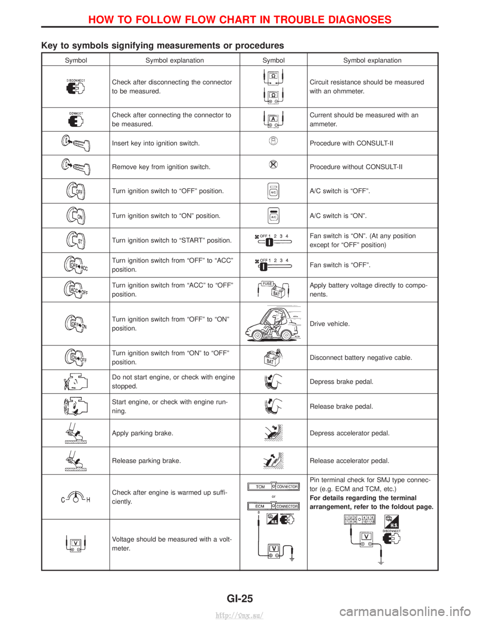
Key to symbols signifying measurements or procedures
SymbolSymbol explanation SymbolSymbol explanation
Check after disconnecting the connector
to be measured.Circuit resistance should be measured
with an ohmmeter.
Check after connecting the connector to
be measured.Current should be measured with an
ammeter.
Insert key into ignition switch.Procedure with CONSULT-II
Remove key from ignition switch.Procedure without CONSULT-II
Turn ignition switch to ªOFFº position.A/C switch is ªOFFº.
Turn ignition switch to ªONº position.A/C switch is ªONº.
Turn ignition switch to ªSTARTº position.Fan switch is ªONº. (At any position
except for ªOFFº position)
Turn ignition switch from ªOFFº to ªACCº
position.Fan switch is ªOFFº.
Turn ignition switch from ªACCº to ªOFFº
position.Apply battery voltage directly to compo-
nents.
Turn ignition switch from ªOFFº to ªONº
position.Drive vehicle.
Turn ignition switch from ªONº to ªOFFº
position.Disconnect battery negative cable.
Do not start engine, or check with engine
stopped.Depress brake pedal.
Start engine, or check with engine run-
ning.Release brake pedal.
Apply parking brake.Depress accelerator pedal.
Release parking brake.Release accelerator pedal.
Check after engine is warmed up suffi-
ciently.
Pin terminal check for SMJ type connec-
tor (e.g. ECM and TCM, etc.)
For details regarding the terminal
arrangement, refer to the foldout page.
Voltage should be measured with a volt-
meter.
HOW TO FOLLOW FLOW CHART IN TROUBLE DIAGNOSES
GI-25
http://vnx.su/
Page 29 of 1833
Function and System Application
Diagnostictest mode Function ENGINE A/T Air bag ABS NATS*1
Self-diagnostic results Self-diagnostic results can be read and erased quickly. xxxxx
ECU discriminated No. Classification number of a replacement ECU can be
read to prevent an incorrect ECU from being installed. ÐÐxÐÐ
Data monitor Input/Output data in the ECM can be read. x xÐxÐ
Active test Diagnostic Test Mode in which CONSULT-II drives
some actuators apart from the ECMs and also shifts
some parameters in a specified range. xÐÐxÐ
ECU (ECM) part number ECU (ECM) part number can be read. x xÐxÐ
Control unit initialisation All registered ignition key IDs in NATS components can
be initialised and new IDs can be registered. ÐÐÐÐ x
Self-function check ECM checks its own NATS communication interface. ÐÐÐÐ x
x: Applicable
*1: NATS: Nissan Anti-Theft System
Nickel Metal Hydride Battery Replacement
CONSULT-II contains a nickel metal hydride battery. When replacing the battery obey the following:
WARNING:
Replace the nickel metal hydride battery with genuine CONSULT-II battery only. Use of another battery
may present a risk of fire or explosion. The battery may present a fire or chemical burn hazard if mis-
treated. Do not recharge, disassemble of dispose of in fire.
Keep the battery out of reach of children and discard used battery conforming to the local regulations.
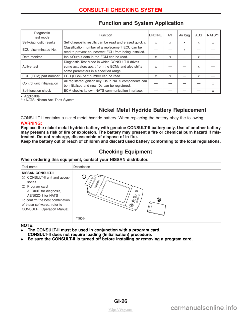
Checking Equipment
When ordering this equipment, contact your NISSAN distributor.
Tool name Description
NISSAN CONSULT-II
q
1CONSULT-II unit and acces-
sories
q
2Program card
AED03E for diagnosis,
AEN02C-1 for NATS
To confirm the best combination
of these softwares, refer to
CONSULT-II Operation Manual.
YGI004
NOTE:
I The CONSULT-II must be used in conjunction with a program card.
CONSULT-II does not require loading (Initialisation) procedure.
I Be sure the CONSULT-II is turned off before installing or removing a program card.
CONSULT-II CHECKING SYSTEM
GI-26
http://vnx.su/
Page 44 of 1833
Shown below are Pre-delivery Inspection items required for the new vehicle. It is recommended that
necessary items other than those listed here be added, paying due regard to the conditions in each
country.
Perform applicable items on each model. Consult text of this section for specifications.
UNDER HOOD Ð engine off
lRadiator coolant level and coolant hose connections for leaks
l Battery fluid level, specific gravity and conditions of battery terminals
l Drive belts tension
l Fuel filter for water or dust, and fuel lines and connections for leaks
l Engine oil level and oil leaks
l Brake and clutch reservoirs fluid level and fluid lines for leaks
l Windshield and rear window washer and headlamp cleaner reservoir fluid level
l Power steering reservoir fluid level and hose connections for leaks
ON INSIDE AND OUTSIDE
lRemove front spring/strut spacer (if applicable)
l Operation of all instruments, gauges, lights and accessories
l Operation of horn(s), wiper and washer
l Steering lock for operation
l Check air conditioner for gas leaks
l Front and rear seats, and seat belts for operation
l All moldings, trims and fittings for fit and alignment
l All windows for operation and alignment
l Hood, tailgate, door panels for fit and alignment
l Latches, keys and locks for operation
l Weatherstrips for adhesion and fit
l Headlamp aiming
l Tighten wheel nuts (Inc. inner nuts if applicable)
l Tire pressure (Inc. spare tire)
l Check front wheels for toe-in
l Install clock/voltmeter/room lamp fuse (if applicable)
l Install deodorizing filter to air conditioner (if applicable)
l Remove wiper blade protectors (if applicable)
UNDER BODY
lManual transmission/transaxle, transfer and differential gear oil level
l Brake and fuel lines and oil/fluid reservoirs for leaks
l Tighten bolts and nuts of steering linkage and gear box, suspension, propeller shafts and drive shafts
l Tighten rear body bolts and nuts (Models with wooden bed only)
ROAD TEST
lClutch operation
l Parking brake operation
l Service brake operation
l Automatic transmission/transaxle shift timing and kickdown (if applicable)
l Steering control and returnability
l Engine performance
l Squeaks and rattles
ENGINE OPERATING AND HOT
lAdjust idle speed
l Automatic transmission/transaxle fluid level (if applicable)
l Engine idling and stop knob operation
FINAL INSPECTION
lInstall necessary parts (outside mirror, wheel covers, seat belts, mat, carpet or mud flaps)
l Inspect for interior and exterior metal and paint damage
l Check for spare tire, jack, tools (wheel check) and literature
l Wash, clean interior and exterior
PRE-DELIVERY INSPECTION ITEMS
MA-3
http://vnx.su/
Page 309 of 1833
IIf the battery is disconnected, the emission-related diagnostic information will be lost after approx.
24 hours.
I Erasing the emission-related diagnostic information using CONSULT-II is easier and quicker than
switching the diagnostic test mode using the data link connector.
NATS (Nissan Anti-Theft System)
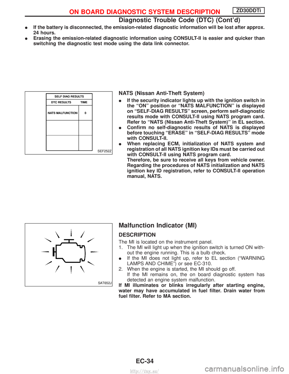
IIf the security indicator lights up with the ignition switch in
the ªONº position or ªNATS MALFUNCTIONº is displayed
on ªSELF-DIAG RESULTSº screen, perform self-diagnostic
results mode with CONSULT-II using NATS program card.
Refer to ªNATS (Nissan Anti-Theft System)º in EL section.
I Confirm no self-diagnostic results of NATS is displayed
before touching ªERASEº in ªSELF-DIAG RESULTSº mode
with CONSULT-II.
I When replacing ECM, initialization of NATS system and
registration of all NATS ignition key IDs must be carried out
with CONSULT-II using NATS program card.
Therefore, be sure to receive all keys from vehicle owner.
Regarding the procedures of NATS initialization and NATS
ignition key ID registration, refer to CONSULT-II operation
manual, NATS.
Malfunction Indicator (MI)
DESCRIPTION
The MI is located on the instrument panel.
1. The MI will light up when the ignition switch is turned ON with-
out the engine running. This is a bulb check.
I If the MI does not light up, refer to EL section (ªWARNING
LAMPS AND CHIMEº) or see EC-310.
2. When the engine is started, the MI should go off. If the MI remains on, the on board diagnostic system has
detected an engine system malfunction.
If MI illuminates or blinks irregularly after starting engine,
water may have accumulated in fuel filter. Drain water from
fuel filter. Refer to MA section.
SEF252Z
SAT652J
ON BOARD DIAGNOSTIC SYSTEM DESCRIPTIONZD30DDTi
Diagnostic Trouble Code (DTC) (Cont'd)
EC-34
http://vnx.su/
Page 616 of 1833
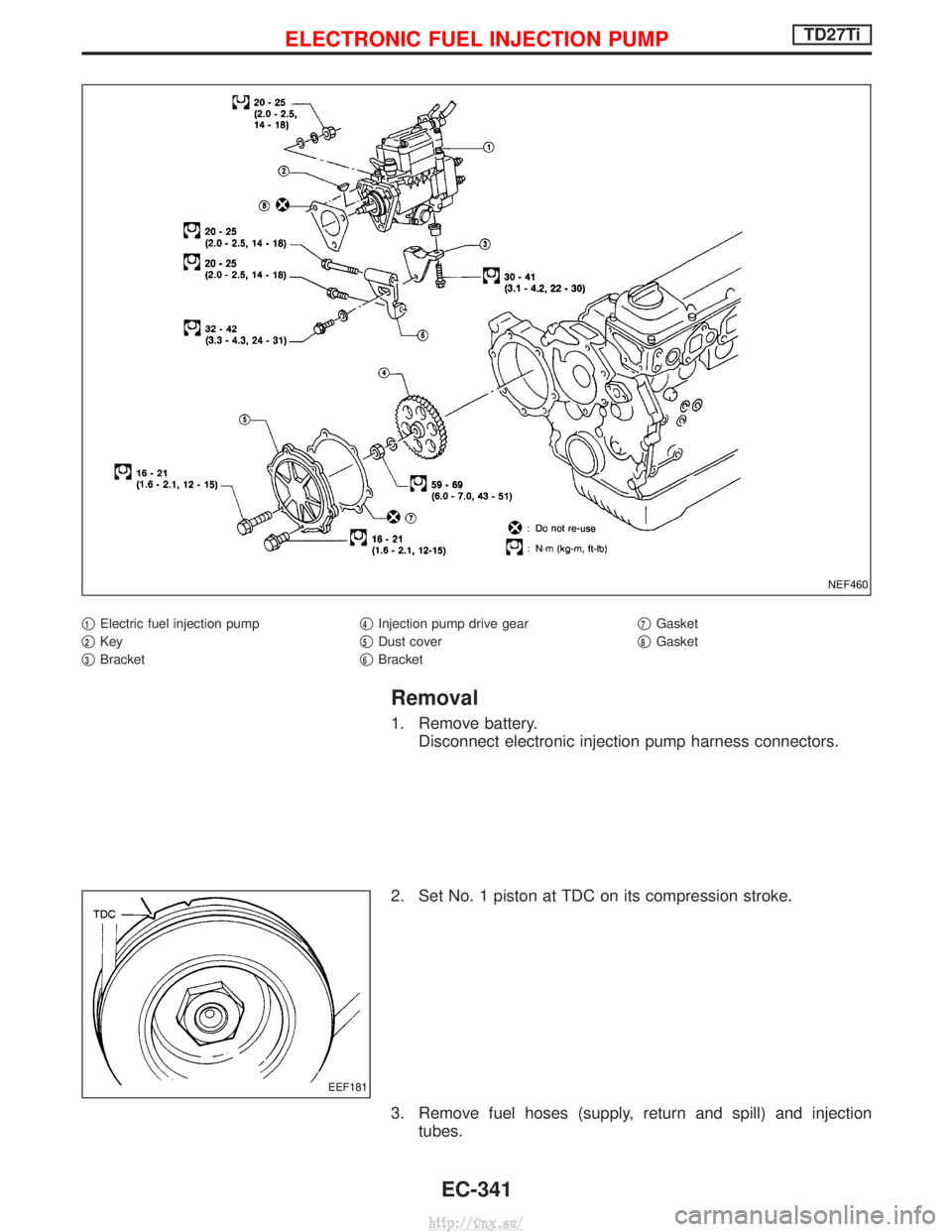
q1Electric fuel injection pump
q
2Key
q
3Bracket q
4Injection pump drive gear
q
5Dust cover
q
6Bracket q
7Gasket
q
8Gasket
Removal
1. Remove battery. Disconnect electronic injection pump harness connectors.
2. Set No. 1 piston at TDC on its compression stroke.
3. Remove fuel hoses (supply, return and spill) and injection tubes.
NEF460
EEF181
ELECTRONIC FUEL INJECTION PUMPTD27Ti
EC-341
http://vnx.su/
Page 620 of 1833
How to Erase DTC (Without CONSULT-II)
1. If the ignition switch stays ªONº after repair work, be sure to turn ignition switch ªOFFº once. Wait at least5 seconds and then turn it ªONº (engine stopped) again.
2. Change the diagnostic test mode from Mode II to Mode I by using the data link connector. (See EC-346.)
The emission related diagnostic information in the ECM can be erased by changing the diagnostic test mode.
I If the battery is disconnected, the emission-related diagnostic information will be lost after approx.
24 hours.
I Erasing the emission-related diagnostic information using CONSULT-II is easier and quicker than
switching the diagnostic test mode using the data link connector.
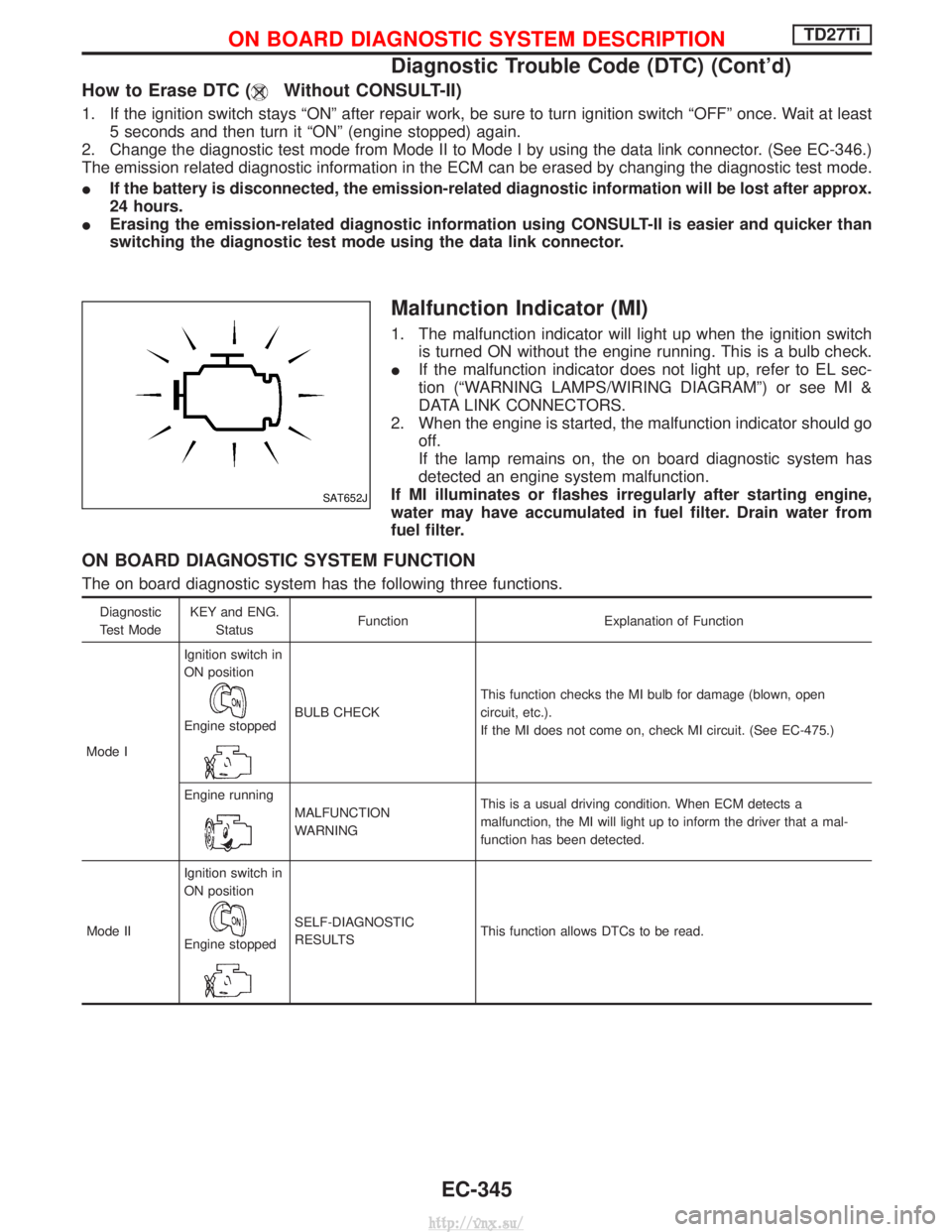
Malfunction Indicator (MI)
1. The malfunction indicator will light up when the ignition switch
is turned ON without the engine running. This is a bulb check.
I If the malfunction indicator does not light up, refer to EL sec-
tion (ªWARNING LAMPS/WIRING DIAGRAMº) or see MI &
DATA LINK CONNECTORS.
2. When the engine is started, the malfunction indicator should go off.
If the lamp remains on, the on board diagnostic system has
detected an engine system malfunction.
If MI illuminates or flashes irregularly after starting engine,
water may have accumulated in fuel filter. Drain water from
fuel filter.
ON BOARD DIAGNOSTIC SYSTEM FUNCTION
The on board diagnostic system has the following three functions.
Diagnostic
Test Mode KEY and ENG.
Status Function Explanation of Function
Mode I Ignition switch in
ON position
Engine stoppedBULB CHECK
This function checks the MI bulb for damage (blown, open
circuit, etc.).
If the MI does not come on, check MI circuit. (See EC-475.)
Engine running
MALFUNCTION
WARNING This is a usual driving condition. When ECM detects a
malfunction, the MI will light up to inform the driver that a mal-
function has been detected.
Mode II Ignition switch in
ON position
Engine stopped
SELF-DIAGNOSTIC
RESULTS
This function allows DTCs to be read.
SAT652J
ON BOARD DIAGNOSTIC SYSTEM DESCRIPTIONTD27Ti
Diagnostic Trouble Code (DTC) (Cont'd)
EC-345
http://vnx.su/
Page 622 of 1833
DIAGNOSTIC TEST MODE IÐBULB CHECK
In this mode, the MALFUNCTION INDICATOR on the instrument panel should stay ON. If it remains OFF,
check the bulb. Refer to EL section (ªWARNING LAMPS/WIRING DIAGRAMº) or see EC-475.
DIAGNOSTIC TEST MODE IÐMALFUNCTION WARNING
MICondition
ON When a malfunction is detected or the ECM's CPU is malfunctioning.
OFF No malfunction.
I These Diagnostic Trouble Code Numbers are clarified in Diagnostic Test Mode II (SELF-DIAGNOSTIC
RESULTS).
DIAGNOSTIC TEST MODE IIÐSELF-DIAGNOSTIC RESULTS
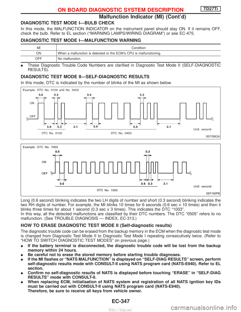
In this mode, DTC is indicated by the number of blinks of the MI as shown below.
Long (0.6 second) blinking indicates the two LH digits of number and short (0.3 second) blinking indicates the
two RH digits of number. For example, the MI blinks 10 times for 6 seconds (0.6 sec x 10 times) and then it
blinks three times for about 1 second (0.3 sec x 3 times). This indicates the DTC ª1003º.
In this way, all the detected malfunctions are classified by their DTC numbers. The DTC ª0505º refers to no
malfunction. (See TROUBLE DIAGNOSIS Ð INDEX, EC-313.)
HOW TO ERASE DIAGNOSTIC TEST MODE II (Self-diagnostic results)
The diagnostic trouble code can be erased from the backup memory in the ECM when the diagnostic test mode
is changed from Diagnostic Test Mode II to Diagnostic Test Mode I repeating consecutively twice. (Refer to
ªHOW TO SWITCH DIAGNOSTIC TEST MODESº on previous page.)
IIf the battery terminal is disconnected, the diagnostic trouble code will be lost from the backup
memory within 24 hours.
I Be careful not to erase the stored memory before starting trouble diagnoses.
I If the MI flashes or ªNATS MALFUNCTIONº is displayed on ªSELF-DIAG RESULTSº screen, perform
self-diagnostic results mode with CONSULT-II using NATS program card (NATS-E940). Refer to EL
section.
I Confirm no self-diagnostic results of NATS is displayed before touching ªERASEº in ªSELF-DIAG
RESULTSº mode with CONSULT-II.
I When replacing ECM, initialisation of NATS system and registration of all NATS ignition key IDs
must be carried out with CONSULT-II using NATS program card (NATS-E940).
Therefore, be sure to receive all keys from vehicle owner.
SEF298QA
SEF162PB
ON BOARD DIAGNOSTIC SYSTEM DESCRIPTIONTD27Ti
Malfunction Indicator (MI) (Cont'd)
EC-347
http://vnx.su/
Page 1315 of 1833
![NISSAN TERRANO 2004 Service Repair Manual If no malfunction is detected on ªSELF-DIAG [CURRENT]º but mal-
function is indicated by the ªAIR BAGº warning lamp, go to DIAG-
NOSTIC PROCEDURE 4, page RS-44, to diagnose the following
situation NISSAN TERRANO 2004 Service Repair Manual If no malfunction is detected on ªSELF-DIAG [CURRENT]º but mal-
function is indicated by the ªAIR BAGº warning lamp, go to DIAG-
NOSTIC PROCEDURE 4, page RS-44, to diagnose the following
situation](/img/5/57394/w960_57394-1314.png)
If no malfunction is detected on ªSELF-DIAG [CURRENT]º but mal-
function is indicated by the ªAIR BAGº warning lamp, go to DIAG-
NOSTIC PROCEDURE 4, page RS-44, to diagnose the following
situations:
ISelf-diagnostic result ªSELF-DIAG [PAST]º (previously stored
in the memory) might not be erased after repair.
I The SRS system malfunctions intermittently.
8. Touch ªPRINTº.
9. Compare diagnostic codes to ªCONSULT-II Diagnostic Code Chartº, page RS-40.
10. Touch ªBACKº key of CONSULT-II until ªSELECT SYSTEMº appears in order to return to User mode from Diagnosis mode.
11. Turn ignition switch ªOFFº, then turn off and disconnect CONSULT-II, and disconnect both battery cables.
12. Repair the system as outlined by the ªRepair orderº in ªCON- SULT-II Diagnostic Code Chartº, that corresponds to the self-
diagnostic result. For replacement procedure of component
parts, refer to RS-13.
13. After repairing the system, go to DIAGNOSTIC PROCEDURE 3, page RS-42 for final checking.
CONSULT-II DIAGNOSTIC CODE CHART (ªSELF-DIAG
[CURRENT]º)
Diagnostic item Explanation Repair order
ªRecheck SRS at each replacement.º
NO DTC IS
DETECTED. When malfunction is
indicated by the ªAIR
BAGº warning lamp is
user mode.I
Self-diagnostic result ªSELF-DIAG
[PAST]º (previously stored in the
memory) might not be erased after
repair.
I Intermittent malfunction has been
detected in the past. I
Go to DIAGNOSTIC PROCEDURE 4
(RS-42) after charging battery.
I No malfunction is detected. IGo to DIAGNOSTIC PROCEDURE 3
(RS-42).
AIRBAG MODULE
[OPEN] I
Driver air bag module circuit is open. (including the spiral
cable) 1. Visually check the wiring harness
connection.
2. Replace the harness if it has visible damage.
3. Replace the spiral cable.
4. Replace driver air bag module. (Before disposal, it must be
deployed.)
5. Replace the diagnosis sensor unit.
6. Replace the related harness.
AIRBAG MODULE
[VB-SHORT]
I
Driver air bag module circuit is shorted to a power supply cir-
cuit. (including the spiral cable)
AIRBAG MODULE
[GND-SHORT] I
Driver air bag module circuit is shorted to ground. (including
the spiral cable)
AIRBAG MODULE
[SHORT] I
Driver air bag module circuit is shorted between wires.
SRS701
SUPPLEMENTAL RESTRAINT SYSTEM (SRS)
Trouble Diagnoses with CONSULT-II (Cont'd)
RS-40
http://vnx.su/
Page 1321 of 1833
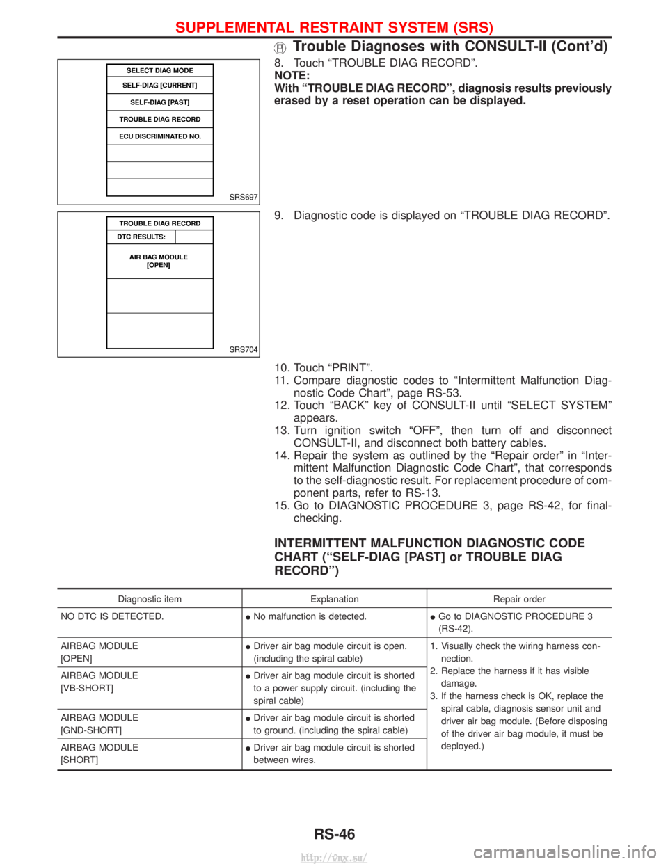
8. Touch ªTROUBLE DIAG RECORDº.
NOTE:
With ªTROUBLE DIAG RECORDº, diagnosis results previously
erased by a reset operation can be displayed.
9. Diagnostic code is displayed on ªTROUBLE DIAG RECORDº.
10. Touch ªPRINTº.
11. Compare diagnostic codes to ªIntermittent Malfunction Diag-nostic Code Chartº, page RS-53.
12. Touch ªBACKº key of CONSULT-II until ªSELECT SYSTEMº appears.
13. Turn ignition switch ªOFFº, then turn off and disconnect CONSULT-II, and disconnect both battery cables.
14. Repair the system as outlined by the ªRepair orderº in ªInter- mittent Malfunction Diagnostic Code Chartº, that corresponds
to the self-diagnostic result. For replacement procedure of com-
ponent parts, refer to RS-13.
15. Go to DIAGNOSTIC PROCEDURE 3, page RS-42, for final- checking.
INTERMITTENT MALFUNCTION DIAGNOSTIC CODE
CHART (ªSELF-DIAG [PAST] or TROUBLE DIAG
RECORDº)
Diagnostic item ExplanationRepair order
NO DTC IS DETECTED. INo malfunction is detected. IGo to DIAGNOSTIC PROCEDURE 3
(RS-42).
AIRBAG MODULE
[OPEN] I
Driver air bag module circuit is open.
(including the spiral cable) 1. Visually check the wiring harness con-
nection.
2. Replace the harness if it has visible damage.
3. If the harness check is OK, replace the spiral cable, diagnosis sensor unit and
driver air bag module. (Before disposing
of the driver air bag module, it must be
deployed.)
AIRBAG MODULE
[VB-SHORT]
I
Driver air bag module circuit is shorted
to a power supply circuit. (including the
spiral cable)
AIRBAG MODULE
[GND-SHORT] I
Driver air bag module circuit is shorted
to ground. (including the spiral cable)
AIRBAG MODULE
[SHORT] I
Driver air bag module circuit is shorted
between wires.
SRS697
SRS704
SUPPLEMENTAL RESTRAINT SYSTEM (SRS)
Trouble Diagnoses with CONSULT-II (Cont'd)
RS-46
http://vnx.su/
Page 1671 of 1833
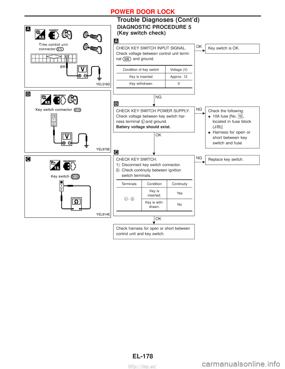
DIAGNOSTIC PROCEDURE 5
(Key switch check)
CHECK KEY SWITCH INPUT SIGNAL.
Check voltage between control unit termi-
nal
U22and ground.
NG
EOKKey switch is OK.
CHECK KEY SWITCH POWER SUPPLY.
Check voltage between key switch har-
ness terminal q
2and ground.
Battery voltage should exist.
OK
ENG Check the following.
I10A fuse [No.
16,
located in fuse block
(J/B)]
I Harness for open or
short between key
switch and fuse
CHECK KEY SWITCH.
1) Disconnect key switch connector.
2) Check continuity between ignition switch terminals.
OK
ENG Replace key switch.
Check harness for open or short between
control unit and key switch.
Condition of key switch Voltage (V)
Key is inserted Approx. 12Key withdrawn 0
Terminals Condition Continuity
q
1-q2
Key is
inserted. Ye s
Key is with- drawn. No
YEL316D
YEL979E
YEL914E
H
H
H
POWER DOOR LOCK
Trouble Diagnoses (Cont'd)
EL-178
http://vnx.su/