charging NISSAN TERRANO 2004 Service Repair Manual
[x] Cancel search | Manufacturer: NISSAN, Model Year: 2004, Model line: TERRANO, Model: NISSAN TERRANO 2004Pages: 1833, PDF Size: 53.42 MB
Page 2 of 1833
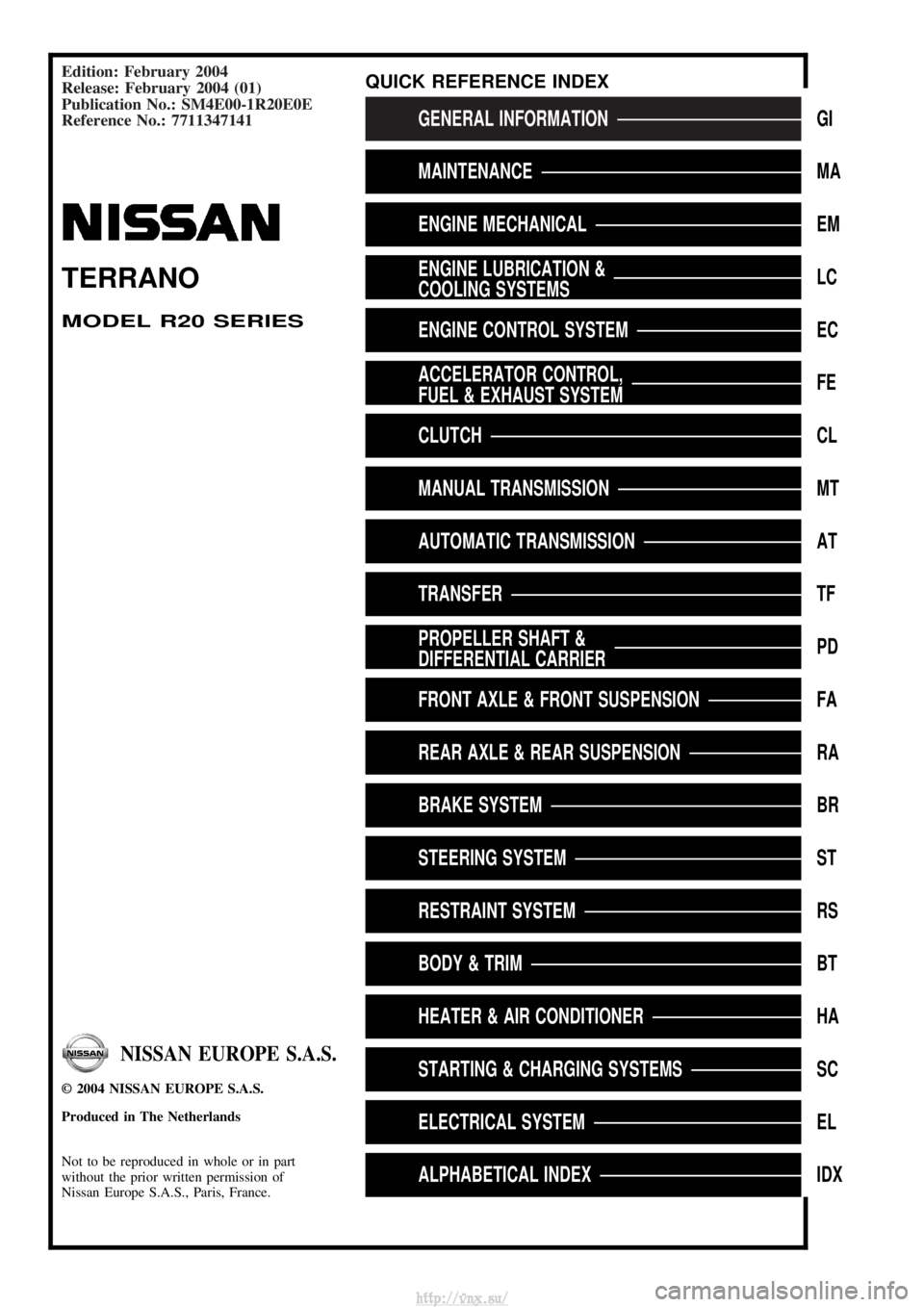
Edition: February 2004
Release: February 2004 (01)
Publication No.: SM4E00-1R20E0E
Reference No.: 7711347141
GENERAL INFORMATIONGI
MAINTENANCEMA
ENGINE MECHANICALEM
ENGINE LUBRICATION &
COOLING SYSTEMSLC
ENGINE CONTROL SYSTEMEC
ACCELERATOR CONTROL,
FUEL & EXHAUST SYSTEMFE
CLUTCHCL
MANUAL TRANSMISSIONMT
AUTOMATIC TRANSMISSIONAT
TRANSFERTF
PROPELLER SHAFT &
DIFFERENTIAL CARRIERPD
FRONT AXLE & FRONT SUSPENSIONFA
REAR AXLE & REAR SUSPENSIONRA
BRAKE SYSTEMBR
STEERING SYSTEMST
RESTRAINT SYSTEMRS
BODY & TRIMBT
HEATER & AIR CONDITIONERHA
STARTING & CHARGING SYSTEMSSC
ELECTRICAL SYSTEMEL
ALPHABETICAL INDEXIDX
TERRANO
MODEL R20 SERIES
NISSAN EUROPE S.A.S.
2004 NISSAN EUROPE S.A.S.
Produced in The Netherlands
Not to be reproduced in whole or in part
without the prior written permission of
Nissan Europe S.A.S., Paris, France.
QUICK REFERENCE INDEX
http://vnx.su/
Page 858 of 1833
FON vehicleEFOFF vehicleE
Reference page (AT- )27,
120 11 9 56,
62,
82 30
65,
144 68,
86 71,
74 78,
11 8 11 8 11 8 144,
128 156,
160 162162,
170 166,
176 180
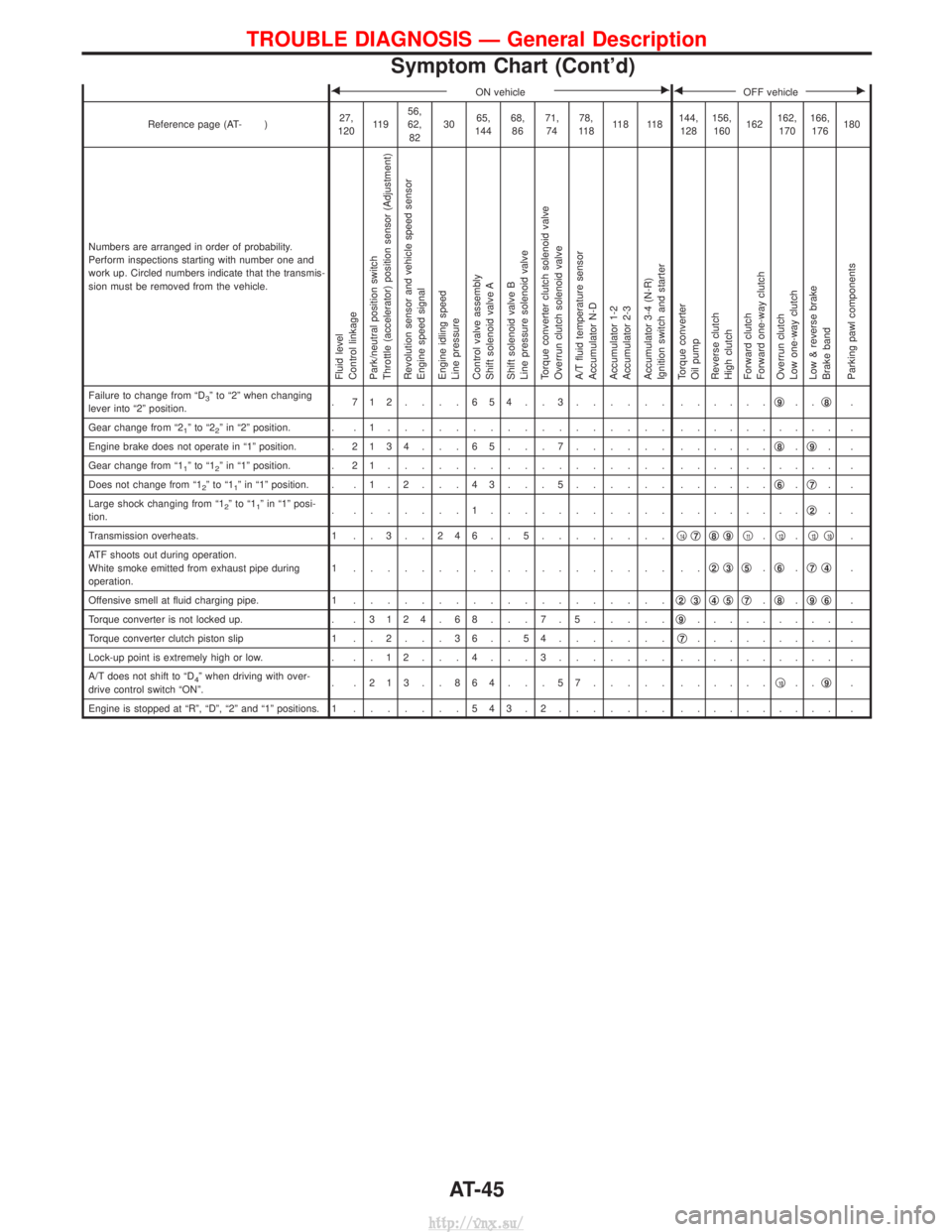
Numbers are arranged in order of probability.
Perform inspections starting with number one and
work up. Circled numbers indicate that the transmis-
sion must be removed from the vehicle.
Fluid level
Control linkage
Park/neutral position switch
Throttle (accelerator) position sensor (Adjustment)
Revolution sensor and vehicle speed sensor
Engine speed signal
Engine idling speed
Line pressure
Control valve assembly
Shift solenoid valve A
Shift solenoid valve B
Line pressure solenoid valve
Torque converter clutch solenoid valve
Overrun clutch solenoid valve
A/T fluid temperature sensor
Accumulator N-D
Accumulator 1-2
Accumulator 2-3
Accumulator 3-4 (N-R)
Ignition switch and starter
Torque converter
Oil pump
Reverse clutch
High clutch
Forward clutch
Forward one-way clutch
Overrun clutch
Low one-way clutch
Low & reverse brake
Brake band
Parking pawl components
Failure to change from ªD3º to ª2º when changing
lever into ª2º position. . 712....654..3...... .
.....q9..q8.
Gear change from ª2
1ºtoª22º in ª2º position. . . 1 ................. . ......... .
Engine brake does not operate in ª1º position. . 2134 . . . 65 . . . 7...... ......q
8.q9..
Gear change from ª1
1ºtoª12º in ª1º position. . 2 1 ................. . ......... .
Does not change from ª1
2ºtoª11º in ª1º position. . . 1 . 2 . . . 4 3 . . . 5 ...... ......q6.q7..
Large shock changing from ª1
2ºtoª11º in ª1º posi-
tion. . .......1........... .
.......q2..
Transmission overheats. 1 . . 3 . . 2 4 6 . . 5 ........q
14q7q8q9q11.q12.q13q10.
ATF shoots out during operation.
White smoke emitted from exhaust pipe during
operation. 1 ................... ..
q
2q3q5.q6.q7q4.
Offensive smell at fluid charging pipe. 1 ................... q
2q3q4q5q7.q8.q9q6.
Torque converter is not locked up. . . 3124 . 68 . . . 7 . 5.....q
9......... .
Torque converter clutch piston slip 1 . . 2 . . . 3 6 . . 5 4 .......q
7......... .
Lock-up point is extremely high or low. . . . 1 2 . . . 4 . . . 3 ....... .......... .
A/T does not shift to ªD
4º when driving with over-
drive control switch ªONº. . .213..864...57..... .
.....q10..q9.
Engine is stopped at ªRº, ªDº, ª2º and ª1º positions. 1 .......543.2....... . ......... .
TROUBLE DIAGNOSIS Ð General Description
Symptom Chart (Cont'd)
AT-45
http://vnx.su/
Page 934 of 1833
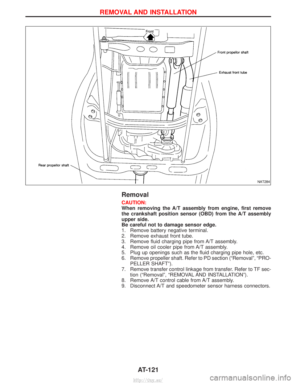
Removal
CAUTION:
When removing the A/T assembly from engine, first remove
the crankshaft position sensor (OBD) from the A/T assembly
upper side.
Be careful not to damage sensor edge.
1. Remove battery negative terminal.
2. Remove exhaust front tube.
3. Remove fluid charging pipe from A/T assembly.
4. Remove oil cooler pipe from A/T assembly.
5. Plug up openings such as the fluid charging pipe hole, etc.
6. Remove propeller shaft. Refer to PD section (ªRemovalº, ªPRO-PELLER SHAFTº).
7. Remove transfer control linkage from transfer. Refer to TF sec- tion (ªRemovalº, ªREMOVAL AND INSTALLATIONº).
8. Remove A/T control cable from A/T assembly.
9. Disconnect A/T and speedometer sensor harness connectors.
NAT284
REMOVAL AND INSTALLATION
AT-121
http://vnx.su/
Page 1315 of 1833
![NISSAN TERRANO 2004 Service Repair Manual If no malfunction is detected on ªSELF-DIAG [CURRENT]º but mal-
function is indicated by the ªAIR BAGº warning lamp, go to DIAG-
NOSTIC PROCEDURE 4, page RS-44, to diagnose the following
situation NISSAN TERRANO 2004 Service Repair Manual If no malfunction is detected on ªSELF-DIAG [CURRENT]º but mal-
function is indicated by the ªAIR BAGº warning lamp, go to DIAG-
NOSTIC PROCEDURE 4, page RS-44, to diagnose the following
situation](/img/5/57394/w960_57394-1314.png)
If no malfunction is detected on ªSELF-DIAG [CURRENT]º but mal-
function is indicated by the ªAIR BAGº warning lamp, go to DIAG-
NOSTIC PROCEDURE 4, page RS-44, to diagnose the following
situations:
ISelf-diagnostic result ªSELF-DIAG [PAST]º (previously stored
in the memory) might not be erased after repair.
I The SRS system malfunctions intermittently.
8. Touch ªPRINTº.
9. Compare diagnostic codes to ªCONSULT-II Diagnostic Code Chartº, page RS-40.
10. Touch ªBACKº key of CONSULT-II until ªSELECT SYSTEMº appears in order to return to User mode from Diagnosis mode.
11. Turn ignition switch ªOFFº, then turn off and disconnect CONSULT-II, and disconnect both battery cables.
12. Repair the system as outlined by the ªRepair orderº in ªCON- SULT-II Diagnostic Code Chartº, that corresponds to the self-
diagnostic result. For replacement procedure of component
parts, refer to RS-13.
13. After repairing the system, go to DIAGNOSTIC PROCEDURE 3, page RS-42 for final checking.
CONSULT-II DIAGNOSTIC CODE CHART (ªSELF-DIAG
[CURRENT]º)
Diagnostic item Explanation Repair order
ªRecheck SRS at each replacement.º
NO DTC IS
DETECTED. When malfunction is
indicated by the ªAIR
BAGº warning lamp is
user mode.I
Self-diagnostic result ªSELF-DIAG
[PAST]º (previously stored in the
memory) might not be erased after
repair.
I Intermittent malfunction has been
detected in the past. I
Go to DIAGNOSTIC PROCEDURE 4
(RS-42) after charging battery.
I No malfunction is detected. IGo to DIAGNOSTIC PROCEDURE 3
(RS-42).
AIRBAG MODULE
[OPEN] I
Driver air bag module circuit is open. (including the spiral
cable) 1. Visually check the wiring harness
connection.
2. Replace the harness if it has visible damage.
3. Replace the spiral cable.
4. Replace driver air bag module. (Before disposal, it must be
deployed.)
5. Replace the diagnosis sensor unit.
6. Replace the related harness.
AIRBAG MODULE
[VB-SHORT]
I
Driver air bag module circuit is shorted to a power supply cir-
cuit. (including the spiral cable)
AIRBAG MODULE
[GND-SHORT] I
Driver air bag module circuit is shorted to ground. (including
the spiral cable)
AIRBAG MODULE
[SHORT] I
Driver air bag module circuit is shorted between wires.
SRS701
SUPPLEMENTAL RESTRAINT SYSTEM (SRS)
Trouble Diagnoses with CONSULT-II (Cont'd)
RS-40
http://vnx.su/
Page 1317 of 1833
![NISSAN TERRANO 2004 Service Repair Manual Diagnostic itemExplanation Repair order
ªRecheck SRS at each replacement.º
PRE-TEN FRONT RH
[OPEN/VB-SHORT] I
The circuit for front RH seat belt pre-tensioner is open or
shorted to a power supply ci NISSAN TERRANO 2004 Service Repair Manual Diagnostic itemExplanation Repair order
ªRecheck SRS at each replacement.º
PRE-TEN FRONT RH
[OPEN/VB-SHORT] I
The circuit for front RH seat belt pre-tensioner is open or
shorted to a power supply ci](/img/5/57394/w960_57394-1316.png)
Diagnostic itemExplanation Repair order
ªRecheck SRS at each replacement.º
PRE-TEN FRONT RH
[OPEN/VB-SHORT] I
The circuit for front RH seat belt pre-tensioner is open or
shorted to a power supply circuit. 1. Visually check the wiring harness
connections.
2. Replace the harness if it has visible damage.
3. Replace front RH seat belt. (Before disposal, it must be deacti-
vated.)
4. Replace the diagnosis sensor unit.
5. Replace the related harness.
PRE-TEN FRONT RH
[GND-SHORT]
I
The circuit for front RH seat belt pre-tensioner is shorted to
ground.
INDEFINITE FAIL-
URES (AIR BAG) I
A problem which cannot be specified occurs because more
than two parts are out of order. 1. Visually check wiring harness con-
nections.
2. Replace diagnosis sensor unit.
3. Replace spiral cable and air bag modules.
4. Replace air bag and pre-tensioner harness.
5. Replace main harness.
INDEFINITE FAIL-
URES
(PRE-TENSIONER) Driver's and front passenger seat belt pre-tensioners are out of
order.
1. Visually check wiring harness con-
nections.
2. Replace diagnosis sensor unit.
3. Replace spiral cable and air bag modules.
4. Replace air bag and pre-tensioner harness.
5. Replace main harness.
CONTROL UNIT ILow battery voltage (Less than 9V) IGo to DIAGNOSTIC PROCEDURE 3
(RS-42) after charging battery.
I Diagnosis sensor unit is malfunctioning. 1. Visually check the wiring harness
connection.
2. Replace the harness if it has visible damage.
3. Replace diagnosis sensor unit.
4. Replace the related harness.
* Follow the procedures in numerical order when repairing malfunctioning parts. Confirm whether malfunction is eliminated using the
air bag warning lamp or CONSULT-II each time repair is finished. If malfunction is still observed, proceed to the next step. When mal-
function is eliminated, further repair work is not required.
DIAGNOSTIC PROCEDURE 3
Final checking after repairing SRS by using CONSULT-II Ð
Diagnosis mode
1. After repairing SRS, connect both battery cables.
2. Connect CONSULT-II to data link connector.
3. Turn ignition switch from ªOFFº to ªONº.
NRS122
SUPPLEMENTAL RESTRAINT SYSTEM (SRS)
Trouble Diagnoses with CONSULT-II (Cont'd)
RS-42
http://vnx.su/
Page 1402 of 1833
Precautions for Refrigerant Connection
WARNING:
Make sure all refrigerant is discharged into the recycling equipment and the pressure in the system
is less than atmospheric. Then gradually loosen the discharge side hose fitting and remove it.
CAUTION:
When replacing or cleaning refrigerant cycle components, observe the following.
IDo not leave compressor on its side or upside down for more than 10 minutes, as compressor oil
will enter low pressure chamber.
I When connecting tubes, always use a torque wrench and a back-up wrench.
I After disconnecting tubes, plug all openings immediately to prevent entrance of dirt and moisture.
I When installing an air conditioner in the vehicle, the pipes must be connected at the final stage of
the operation. The seal caps of the pipes and other components must not be removed until their
removal is required for connection.
I To prevent the condensation of moisture inside A/C components, components stored in cool areas
should be allowed to warm to the working area temperature before removing the seal caps.
I Thoroughly remove moisture from the refrigeration system before charging the refrigerant.
I Always replace used O-rings.
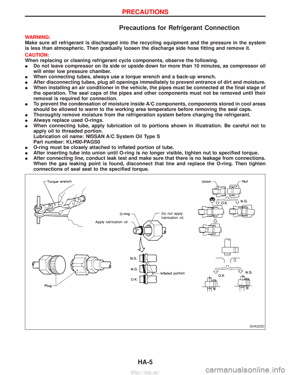
I When connecting tube, apply lubrication oil to portions shown in illustration. Be careful not to
apply oil to threaded portion.
Lubrication oil name: NISSAN A/C System Oil Type S
Part number: KLH00-PAGS0
I O-ring must be closely attached to inflated portion of tube.
I After inserting tube into union until O-ring is no longer visible, tighten nut to specified torque.
I After connecting line, conduct leak test and make sure that there is no leakage from connections.
When the gas leaking point is found, disconnect that line and replace the O-ring. Then tighten
connections of seal seat to the specified torque.
SHA525D
PRECAUTIONS
HA-5
http://vnx.su/
Page 1409 of 1833
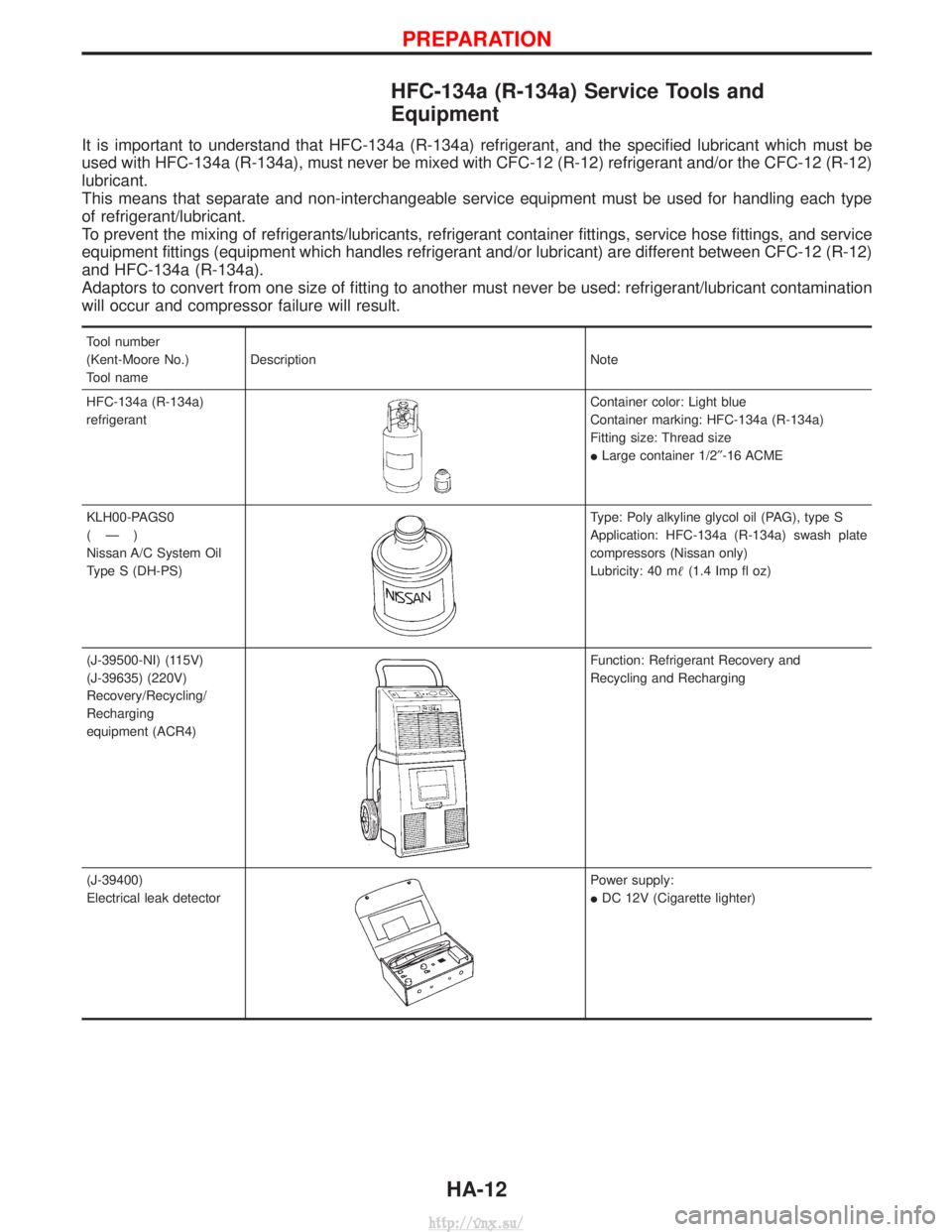
HFC-134a (R-134a) Service Tools and
Equipment
It is important to understand that HFC-134a (R-134a) refrigerant, and the specified lubricant which must be
used with HFC-134a (R-134a), must never be mixed with CFC-12 (R-12) refrigerant and/or the CFC-12 (R-12)
lubricant.
This means that separate and non-interchangeable service equipment must be used for handling each type
of refrigerant/lubricant.
To prevent the mixing of refrigerants/lubricants, refrigerant container fittings, service hose fittings, and service
equipment fittings (equipment which handles refrigerant and/or lubricant) are different between CFC-12 (R-12)
and HFC-134a (R-134a).
Adaptors to convert from one size of fitting to another must never be used: refrigerant/lubricant contamination
will occur and compressor failure will result.
Tool number
(Kent-Moore No.)
Tool nameDescription Note
HFC-134a (R-134a)
refrigerant
Container color: Light blue
Container marking: HFC-134a (R-134a)
Fitting size: Thread size
I Large container 1/2² -16 ACME
KLH00-PAGS0
(Ð)
Nissan A/C System Oil
Type S (DH-PS)
Type: Poly alkyline glycol oil (PAG), type S
Application: HFC-134a (R-134a) swash plate
compressors (Nissan only)
Lubricity: 40 m (1.4 Imp fl oz)
(J-39500-NI) (115V)
(J-39635) (220V)
Recovery/Recycling/
Recharging
equipment (ACR4)
Function: Refrigerant Recovery and
Recycling and Recharging
(J-39400)
Electrical leak detector
Power supply:
I DC 12V (Cigarette lighter)
PREPARATION
HA-12
http://vnx.su/
Page 1411 of 1833
Precautions for Service Equipment
RECOVERY/RECYCLING/RECHARGING EQUIPMENT
Be certain to follow the manufacturers instructions for machine
operation and machine maintenance. Never introduce any refriger-
ant other than that specified into the machine.
ELECTRONIC LEAK DETECTOR
Be certain to follow the manufactures instructions for tester opera-
tion and tester maintenance.
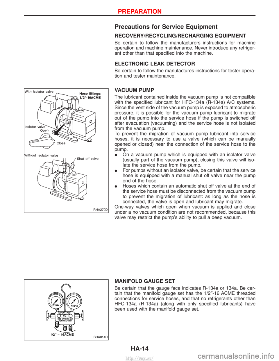
VACUUM PUMP
The lubricant contained inside the vacuum pump is not compatible
with the specified lubricant for HFC-134a (R-134a) A/C systems.
Since the vent side of the vacuum pump is exposed to atmospheric
pressure, it is possible for the vacuum pump lubricant to migrate
out of the pump into the service hose if the pump is switched off
after evacuation (vacuuming) and the service hose is not isolated
from the vacuum pump.
To prevent the migration of vacuum pump lubricant into service
hoses, it is necessary to use a valve (which can be manually
opened or closed) near the connection of the service hose to the
pump.
IOn a vacuum pump which is equipped with an isolator valve
(usually part of the vacuum pump), closing this valve will iso-
late the service hose from the pump.
I For pumps without an isolator valve, be certain that the service
hose is equipped with a manual shut off valve near the pump
end of the hose.
I Hoses which contain an automatic shut off valve at the end of
the service hose must be disconnected from the vacuum pump
to prevent the migration of lubricant: as long as the hose is
connected, the valve is open and lubricant may migrate.
One-way valves which open when vacuum is applied and close
under a no vacuum condition are not recommended, because this
valve may restrict the pump's ability to pull a deep vacuum.
MANIFOLD GAUGE SET
Be certain that the gauge face indicates R-134a or 134a. Be cer-
tain that the manifold gauge set has the 1/2 ²-16 ACME threaded
connections for service hoses, and that no refrigerants other than
HFC-134a (R-134a) (along with only specified lubricants) have
been used with the manifold gauge set.
RHA270D
SHA814D
PREPARATION
HA-14
http://vnx.su/
Page 1412 of 1833
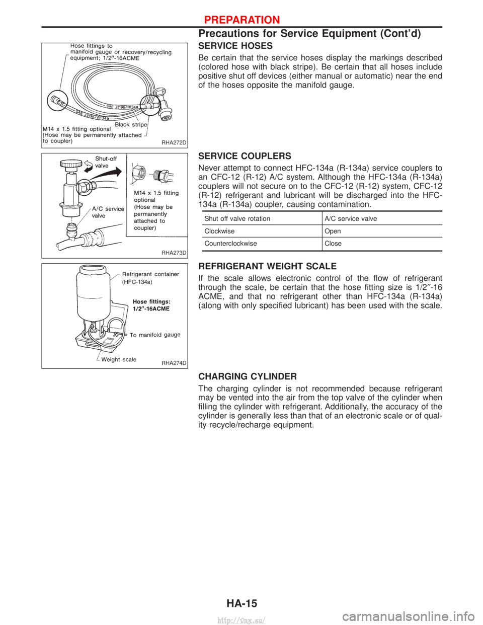
SERVICE HOSES
Be certain that the service hoses display the markings described
(colored hose with black stripe). Be certain that all hoses include
positive shut off devices (either manual or automatic) near the end
of the hoses opposite the manifold gauge.
SERVICE COUPLERS
Never attempt to connect HFC-134a (R-134a) service couplers to
an CFC-12 (R-12) A/C system. Although the HFC-134a (R-134a)
couplers will not secure on to the CFC-12 (R-12) system, CFC-12
(R-12) refrigerant and lubricant will be discharged into the HFC-
134a (R-134a) coupler, causing contamination.
Shut off valve rotationA/C service valve
Clockwise Open
Counterclockwise Close
REFRIGERANT WEIGHT SCALE
If the scale allows electronic control of the flow of refrigerant
through the scale, be certain that the hose fitting size is 1/2 ²-16
ACME, and that no refrigerant other than HFC-134a (R-134a)
(along with only specified lubricant) has been used with the scale.
CHARGING CYLINDER
The charging cylinder is not recommended because refrigerant
may be vented into the air from the top valve of the cylinder when
filling the cylinder with refrigerant. Additionally, the accuracy of the
cylinder is generally less than that of an electronic scale or of qual-
ity recycle/recharge equipment.
RHA272D
RHA273D
RHA274D
PREPARATION
Precautions for Service Equipment (Cont'd)
HA-15
http://vnx.su/
Page 1413 of 1833
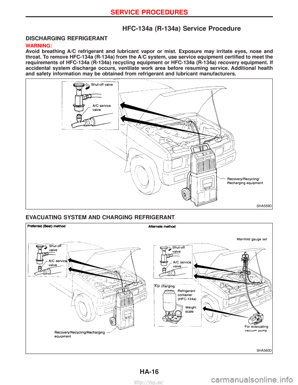
HFC-134a (R-134a) Service Procedure
DISCHARGING REFRIGERANT
WARNING:
Avoid breathing A/C refrigerant and lubricant vapor or mist. Exposure may irritate eyes, nose and
throat. To remove HFC-134a (R-134a) from the A/C system, use service equipment certified to meet the
requirements of HFC-134a (R-134a) recycling equipment or HFC-134a (R-134a) recovery equipment. If
accidental system discharge occurs, ventilate work area before resuming service. Additional health
and safety information may be obtained from refrigerant and lubricant manufacturers.
EVACUATING SYSTEM AND CHARGING REFRIGERANT
SHA559D
SHA560D
SERVICE PROCEDURES
HA-16
http://vnx.su/