open hood NISSAN TERRANO 2004 Service Repair Manual
[x] Cancel search | Manufacturer: NISSAN, Model Year: 2004, Model line: TERRANO, Model: NISSAN TERRANO 2004Pages: 1833, PDF Size: 53.42 MB
Page 45 of 1833
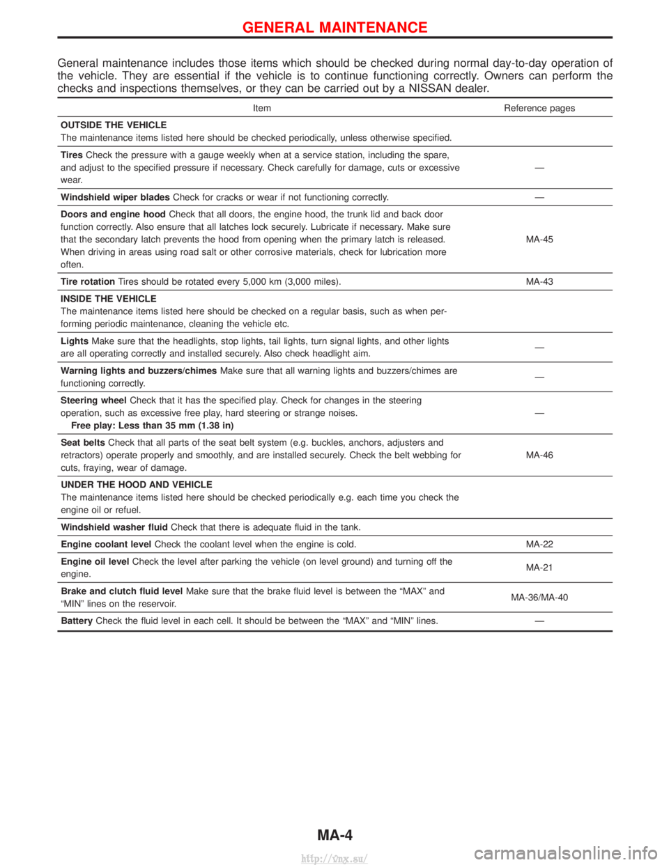
General maintenance includes those items which should be checked during normal day-to-day operation of
the vehicle. They are essential if the vehicle is to continue functioning correctly. Owners can perform the
checks and inspections themselves, or they can be carried out by a NISSAN dealer.
ItemReference pages
OUTSIDE THE VEHICLE
The maintenance items listed here should be checked periodically, unless otherwise specified.
Tires Check the pressure with a gauge weekly when at a service station, including the spare,
and adjust to the specified pressure if necessary. Check carefully for damage, cuts or excessive
wear. Ð
Windshield wiper blades Check for cracks or wear if not functioning correctly. Ð
Doors and engine hood Check that all doors, the engine hood, the trunk lid and back door
function correctly. Also ensure that all latches lock securely. Lubricate if necessary. Make sure
that the secondary latch prevents the hood from opening when the primary latch is released.
When driving in areas using road salt or other corrosive materials, check for lubrication more
often. MA-45
Tire rotation Tires should be rotated every 5,000 km (3,000 miles). MA-43
INSIDE THE VEHICLE
The maintenance items listed here should be checked on a regular basis, such as when per-
forming periodic maintenance, cleaning the vehicle etc.
Lights Make sure that the headlights, stop lights, tail lights, turn signal lights, and other lights
are all operating correctly and installed securely. Also check headlight aim. Ð
Warning lights and buzzers/chimes Make sure that all warning lights and buzzers/chimes are
functioning correctly. Ð
Steering wheel Check that it has the specified play. Check for changes in the steering
operation, such as excessive free play, hard steering or strange noises. Free play: Less than 35 mm (1.38 in) Ð
Seat belts Check that all parts of the seat belt system (e.g. buckles, anchors, adjusters and
retractors) operate properly and smoothly, and are installed securely. Check the belt webbing for
cuts, fraying, wear of damage. MA-46
UNDER THE HOOD AND VEHICLE
The maintenance items listed here should be checked periodically e.g. each time you check the
engine oil or refuel.
Windshield washer fluid Check that there is adequate fluid in the tank.
Engine coolant level Check the coolant level when the engine is cold. MA-22
Engine oil level Check the level after parking the vehicle (on level ground) and turning off the
engine. MA-21
Brake and clutch fluid level Make sure that the brake fluid level is between the ªMAXº and
ªMINº lines on the reservoir. MA-36/MA-40
Battery Check the fluid level in each cell. It should be between the ªMAXº and ªMINº lines. Ð
GENERAL MAINTENANCE
MA-4
http://vnx.su/
Page 88 of 1833
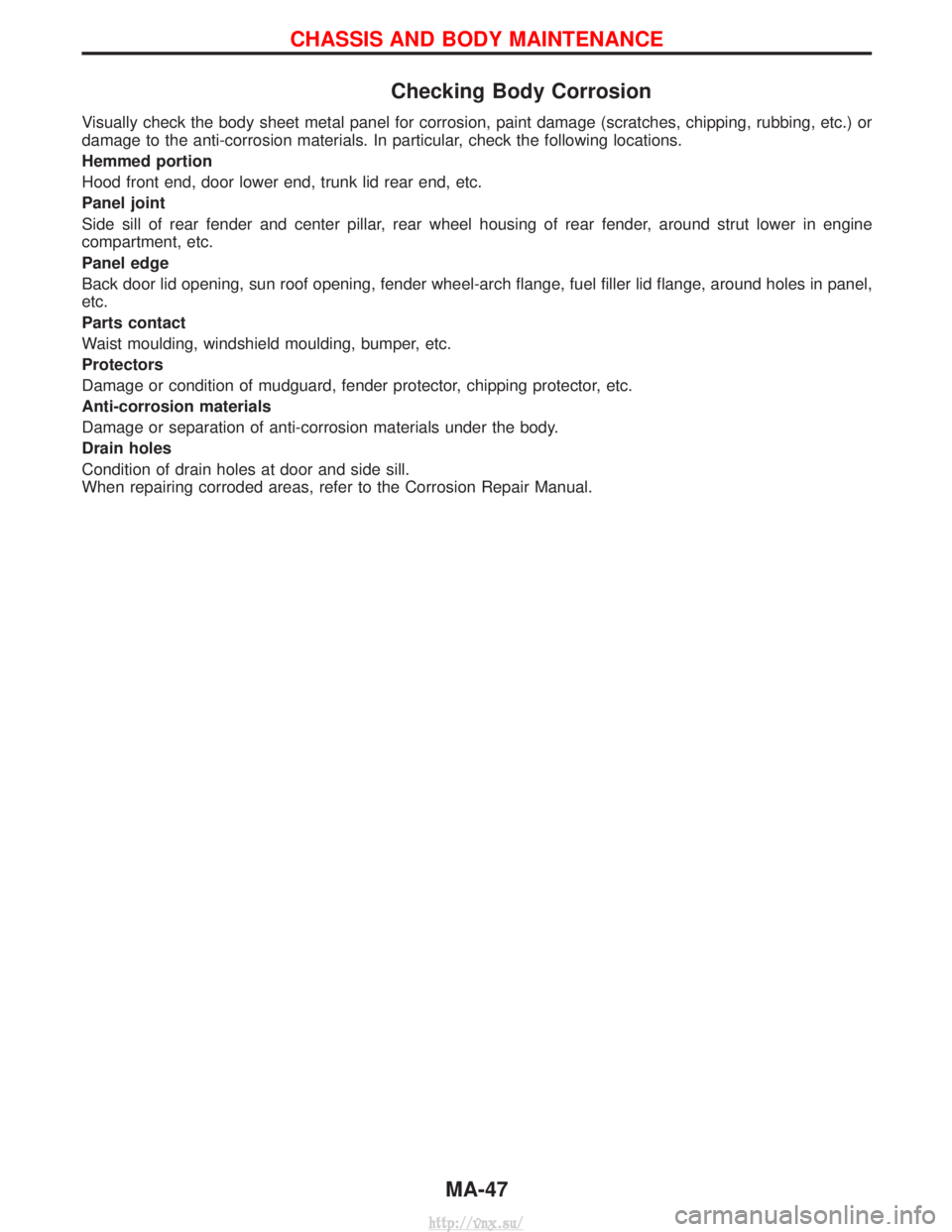
Checking Body Corrosion
Visually check the body sheet metal panel for corrosion, paint damage (scratches, chipping, rubbing, etc.) or
damage to the anti-corrosion materials. In particular, check the following locations.
Hemmed portion
Hood front end, door lower end, trunk lid rear end, etc.
Panel joint
Side sill of rear fender and center pillar, rear wheel housing of rear fender, around strut lower in engine
compartment, etc.
Panel edge
Back door lid opening, sun roof opening, fender wheel-arch flange, fuel filler lid flange, around holes in panel,
etc.
Parts contact
Waist moulding, windshield moulding, bumper, etc.
Protectors
Damage or condition of mudguard, fender protector, chipping protector, etc.
Anti-corrosion materials
Damage or separation of anti-corrosion materials under the body.
Drain holes
Condition of drain holes at door and side sill.
When repairing corroded areas, refer to the Corrosion Repair Manual.
CHASSIS AND BODY MAINTENANCE
MA-47
http://vnx.su/
Page 325 of 1833
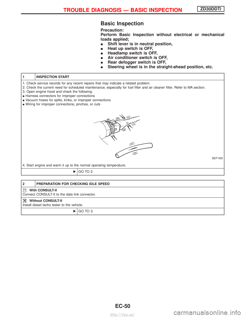
Basic Inspection
Precaution:
Perform Basic Inspection without electrical or mechanical
loads applied;
IShift lever is in neutral position,
I Heat up switch is OFF,
I Headlamp switch is OFF,
I Air conditioner switch is OFF,
I Rear defogger switch is OFF,
I Steering wheel is in the straight-ahead position, etc.
1 INSPECTION START
1. Check service records for any recent repairs that may indicate a related problem.
2. Check the current need for scheduled maintenance, especially for fuel filter and air cleaner filter. Refer to MA section.
3. Open engine hood and check the following:
IHarness connectors for improper connections
I Vacuum hoses for splits, kinks, or improper connections
I Wiring for improper connections, pinches, or cuts
SEF142I
4. Start engine and warm it up to the normal operating temperature.
EGO TO 2.
2 PREPARATION FOR CHECKING IDLE SPEED
With CONSULT-II
Connect CONSULT-II to the data link connector.
Without CONSULT-II
Install diesel tacho tester to the vehicle.
EGO TO 3.
TROUBLE DIAGNOSIS Ð BASIC INSPECTIONZD30DDTi
EC-50
http://vnx.su/
Page 636 of 1833
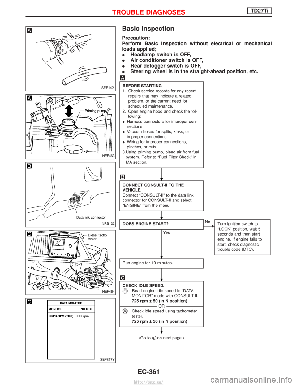
Basic Inspection
Precaution:
Perform Basic Inspection without electrical or mechanical
loads applied;
IHeadlamp switch is OFF,
I Air conditioner switch is OFF,
I Rear defogger switch is OFF,
I Steering wheel is in the straight-ahead position, etc.
BEFORE STARTING
1. Check service records for any recent
repairs that may indicate a related
problem, or the current need for
scheduled maintenance.
2. Open engine hood and check the fol- lowing:
I Harness connectors for improper con-
nections
I Vacuum hoses for splits, kinks, or
improper connections
I Wiring for improper connections,
pinches, or cuts
3.Using priming pump, bleed air from fuel system. Refer to ªFuel Filter Checkº in
MA section.
CONNECT CONSULT-II TO THE
VEHICLE.
Connect ªCONSULT-IIº to the data link
connector for CONSULT-II and select
ªENGINEº from the menu.
DOES ENGINE START?
Ye s
ENo Turn ignition switch to
ªLOCKº position, wait 5
seconds and then start
engine. If engine fails to
start, check diagnostic
trouble code (DTC).
Run engine for 10 minutes.
CHECK IDLE SPEED.
Read engine idle speed in ªDATA
MONITORº mode with CONSULT-II.
725 rpm 50 (in N position)
----------------------------------------------------------------------------------------------------------------------------------- -OR------------------------------------------------------------------------------------------------------------------------------------
Check idle speed using tachometer
tester.
725 rpm 50 (in N position)
(Go to qAon next page.)
SEF142I
NEF463
NRS122
NEF464
SEF817Y
H
H
H
H
H
TROUBLE DIAGNOSESTD27Ti
EC-361
http://vnx.su/
Page 1342 of 1833
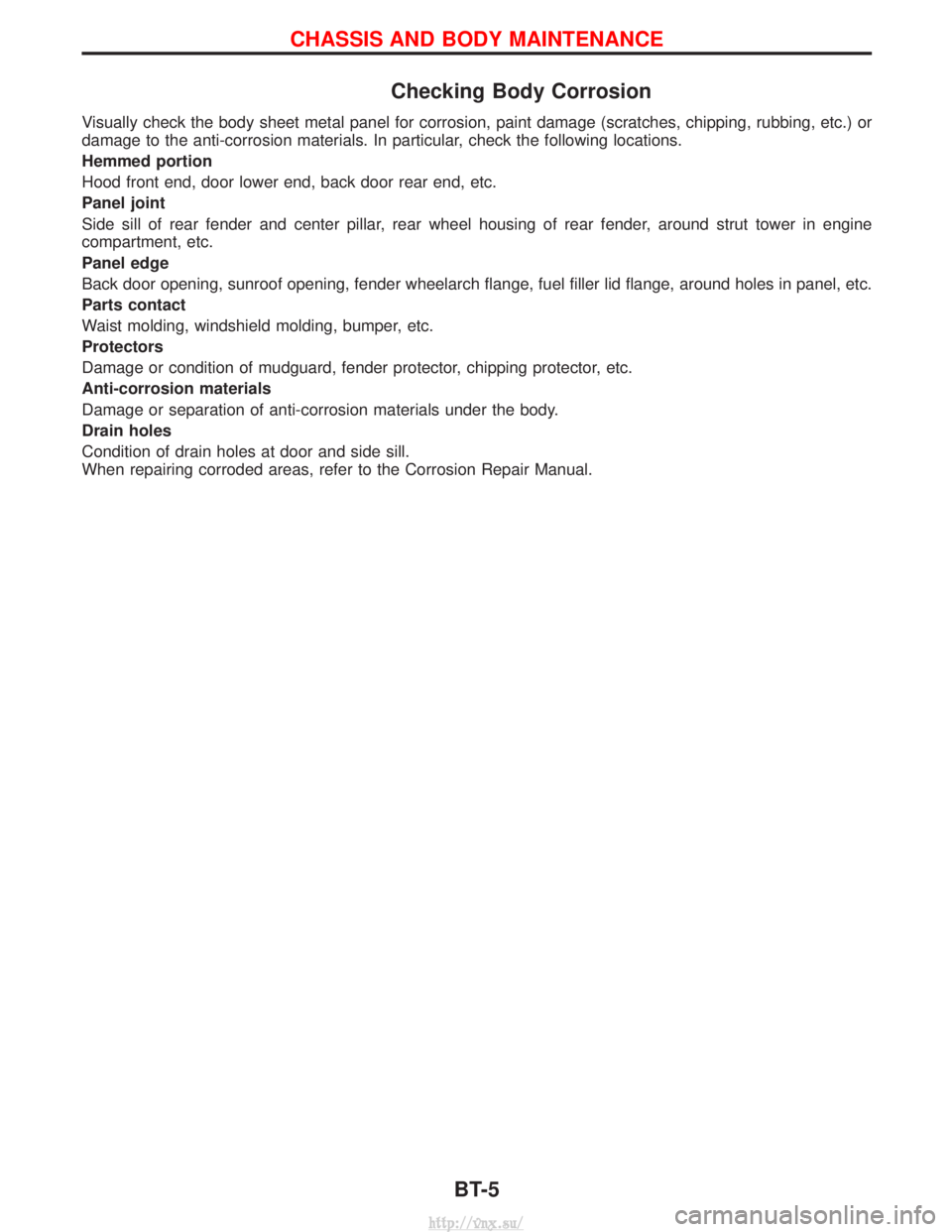
Checking Body Corrosion
Visually check the body sheet metal panel for corrosion, paint damage (scratches, chipping, rubbing, etc.) or
damage to the anti-corrosion materials. In particular, check the following locations.
Hemmed portion
Hood front end, door lower end, back door rear end, etc.
Panel joint
Side sill of rear fender and center pillar, rear wheel housing of rear fender, around strut tower in engine
compartment, etc.
Panel edge
Back door opening, sunroof opening, fender wheelarch flange, fuel filler lid flange, around holes in panel, etc.
Parts contact
Waist molding, windshield molding, bumper, etc.
Protectors
Damage or condition of mudguard, fender protector, chipping protector, etc.
Anti-corrosion materials
Damage or separation of anti-corrosion materials under the body.
Drain holes
Condition of drain holes at door and side sill.
When repairing corroded areas, refer to the Corrosion Repair Manual.
CHASSIS AND BODY MAINTENANCE
BT-5
http://vnx.su/
Page 1343 of 1833
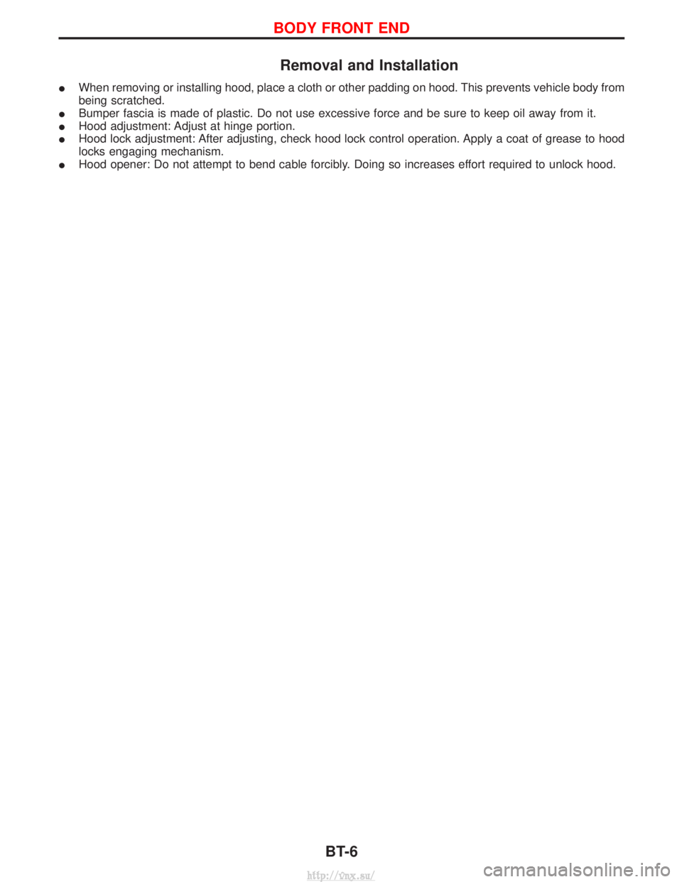
Removal and Installation
IWhen removing or installing hood, place a cloth or other padding on hood. This prevents vehicle body from
being scratched.
I Bumper fascia is made of plastic. Do not use excessive force and be sure to keep oil away from it.
I Hood adjustment: Adjust at hinge portion.
I Hood lock adjustment: After adjusting, check hood lock control operation. Apply a coat of grease to hood
locks engaging mechanism.
I Hood opener: Do not attempt to bend cable forcibly. Doing so increases effort required to unlock hood.
BODY FRONT END
BT-6
http://vnx.su/
Page 1428 of 1833
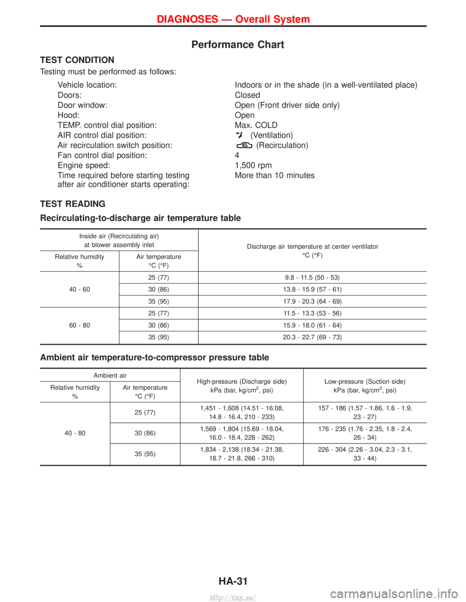
Performance Chart
TEST CONDITION
Testing must be performed as follows:
Vehicle location:Indoors or in the shade (in a well-ventilated place)
Doors: Closed
Door window: Open (Front driver side only)
Hood: Open
TEMP. control dial position: Max. COLD
AIR control dial position:
(Ventilation)
Air recirculation switch position:
(Recirculation)
Fan control dial position: 4
Engine speed: 1,500 rpm
Time required before starting testing
after air conditioner starts operating: More than 10 minutes
TEST READING
Recirculating-to-discharge air temperature table
Inside air (Recirculating air)
at blower assembly inlet Discharge air temperature at center ventilator
ÉC (ÉF)
Relative humidity
% Air temperature
ÉC (ÉF)
40-60 25 (77) 9.8 - 11.5 (50 - 53)
30 (86) 13.8 - 15.9 (57 - 61)
35 (95) 17.9 - 20.3 (64 - 69)
60-80 25 (77) 11.5 - 13.3 (53 - 56)
30 (86) 15.9 - 18.0 (61 - 64)
35 (95) 20.3 - 22.7 (69 - 73)
Ambient air temperature-to-compressor pressure table
Ambient air
High-pressure (Discharge side)
kPa (bar, kg/cm
2, psi) Low-pressure (Suction side)
kPa (bar, kg/cm2, psi)
Relative humidity
% Air temperature
ÉC (ÉF)
40-80 25 (77)
1,451 - 1,608 (14.51 - 16.08,
14.8 - 16.4, 210 - 233) 157 - 186 (1.57 - 1.86, 1.6 - 1.9,
23 - 27)
30 (86) 1,569 - 1,804 (15.69 - 18.04,
16.0 - 18.4, 228 - 262) 176 - 235 (1.76 - 2.35, 1.8 - 2.4,
26 - 34)
35 (95) 1,834 - 2,138 (18.34 - 21.38,
18.7 - 21.8, 266 - 310) 226 - 304 (2.26 - 3.04, 2.3 - 3.1,
33 - 44)
DIAGNOSES Ð Overall System
HA-31
http://vnx.su/
Page 1710 of 1833
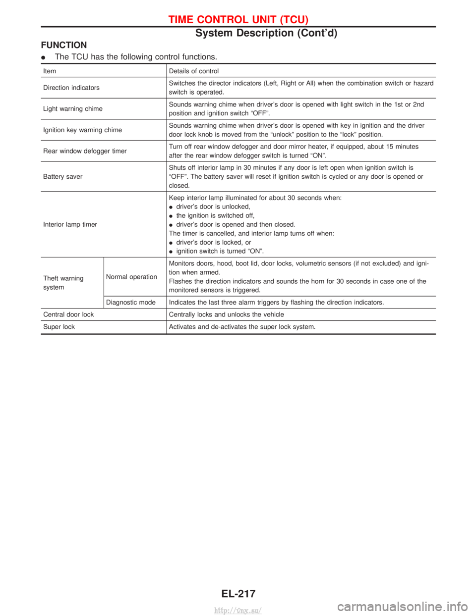
FUNCTION
IThe TCU has the following control functions.
Item Details of control
Direction indicators Switches the director indicators (Left, Right or All) when the combination switch or hazard
switch is operated.
Light warning chime Sounds warning chime when driver's door is opened with light switch in the 1st or 2nd
position and ignition switch ªOFFº.
Ignition key warning chime Sounds warning chime when driver's door is opened with key in ignition and the driver
door lock knob is moved from the ªunlockº position to the ªlockº position.
Rear window defogger timer Turn off rear window defogger and door mirror heater, if equipped, about 15 minutes
after the rear window defogger switch is turned ªONº.
Battery saver Shuts off interior lamp in 30 minutes if any door is left open when ignition switch is
ªOFFº. The battery saver will reset if ignition switch is cycled or any door is opened or
closed.
Interior lamp timer Keep interior lamp illuminated for about 30 seconds when:
I
driver's door is unlocked,
I the ignition is switched off,
I driver's door is opened and then closed.
The timer is cancelled, and interior lamp turns off when:
I driver's door is locked, or
I ignition switch is turned ªONº.
Theft warning
system Normal operationMonitors doors, hood, boot lid, door locks, volumetric sensors (if not excluded) and igni-
tion when armed.
Flashes the direction indicators and sounds the horn for 30 seconds in case one of the
monitored sensors is triggered.
Diagnostic mode Indicates the last three alarm triggers by flashing the direction indicators.
Central door lock Centrally locks and unlocks the vehicle
Super lock Activates and de-activates the super lock system.
TIME CONTROL UNIT (TCU)
System Description (Cont'd)
EL-217
http://vnx.su/
Page 1712 of 1833
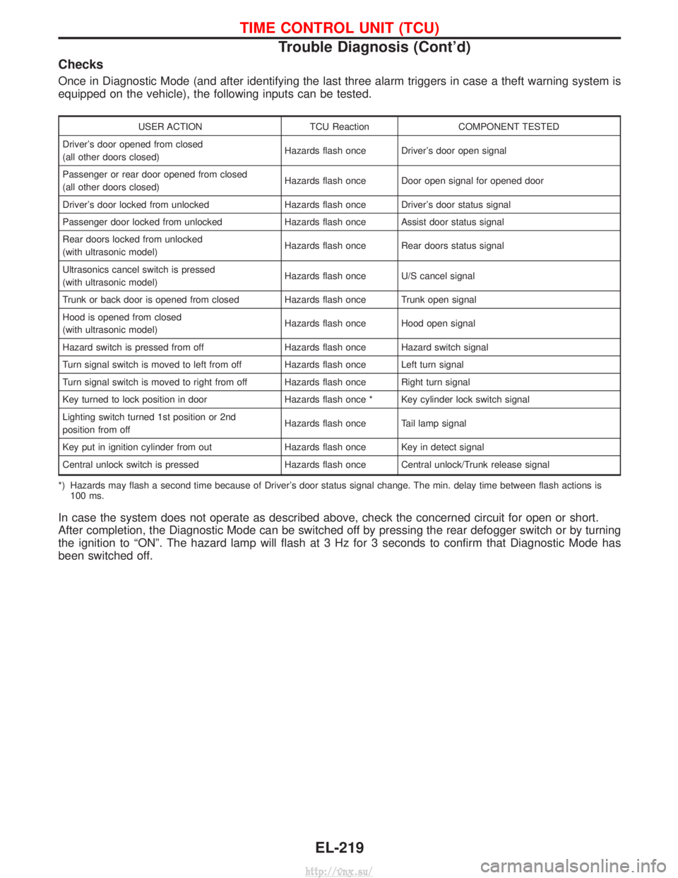
Checks
Once in Diagnostic Mode (and after identifying the last three alarm triggers in case a theft warning system is
equipped on the vehicle), the following inputs can be tested.
USER ACTIONTCU ReactionCOMPONENT TESTED
Driver's door opened from closed
(all other doors closed) Hazards flash once Driver's door open signal
Passenger or rear door opened from closed
(all other doors closed) Hazards flash once Door open signal for opened door
Driver's door locked from unlocked Hazards flash once Driver's door status signal
Passenger door locked from unlocked Hazards flash once Assist door status signal
Rear doors locked from unlocked
(with ultrasonic model) Hazards flash once Rear doors status signal
Ultrasonics cancel switch is pressed
(with ultrasonic model) Hazards flash once U/S cancel signal
Trunk or back door is opened from closed Hazards flash once Trunk open signal
Hood is opened from closed
(with ultrasonic model) Hazards flash once Hood open signal
Hazard switch is pressed from off Hazards flash once Hazard switch signal
Turn signal switch is moved to left from off Hazards flash once Left turn signal
Turn signal switch is moved to right from off Hazards flash once Right turn signal
Key turned to lock position in door Hazards flash once * Key cylinder lock switch signal
Lighting switch turned 1st position or 2nd
position from off Hazards flash once Tail lamp signal
Key put in ignition cylinder from out Hazards flash once Key in detect signal
Central unlock switch is pressed Hazards flash once Central unlock/Trunk release signal
*) Hazards may flash a second time because of Driver's door status signal change. The min. delay time between flash actions is 100 ms.
In case the system does not operate as described above, check the concerned circuit for open or short.
After completion, the Diagnostic Mode can be switched off by pressing the rear defogger switch or by turning
the ignition to ªONº. The hazard lamp will flash at 3 Hz for 3 seconds to confirm that Diagnostic Mode has
been switched off.
TIME CONTROL UNIT (TCU)
Trouble Diagnosis (Cont'd)
EL-219
http://vnx.su/
Page 1738 of 1833
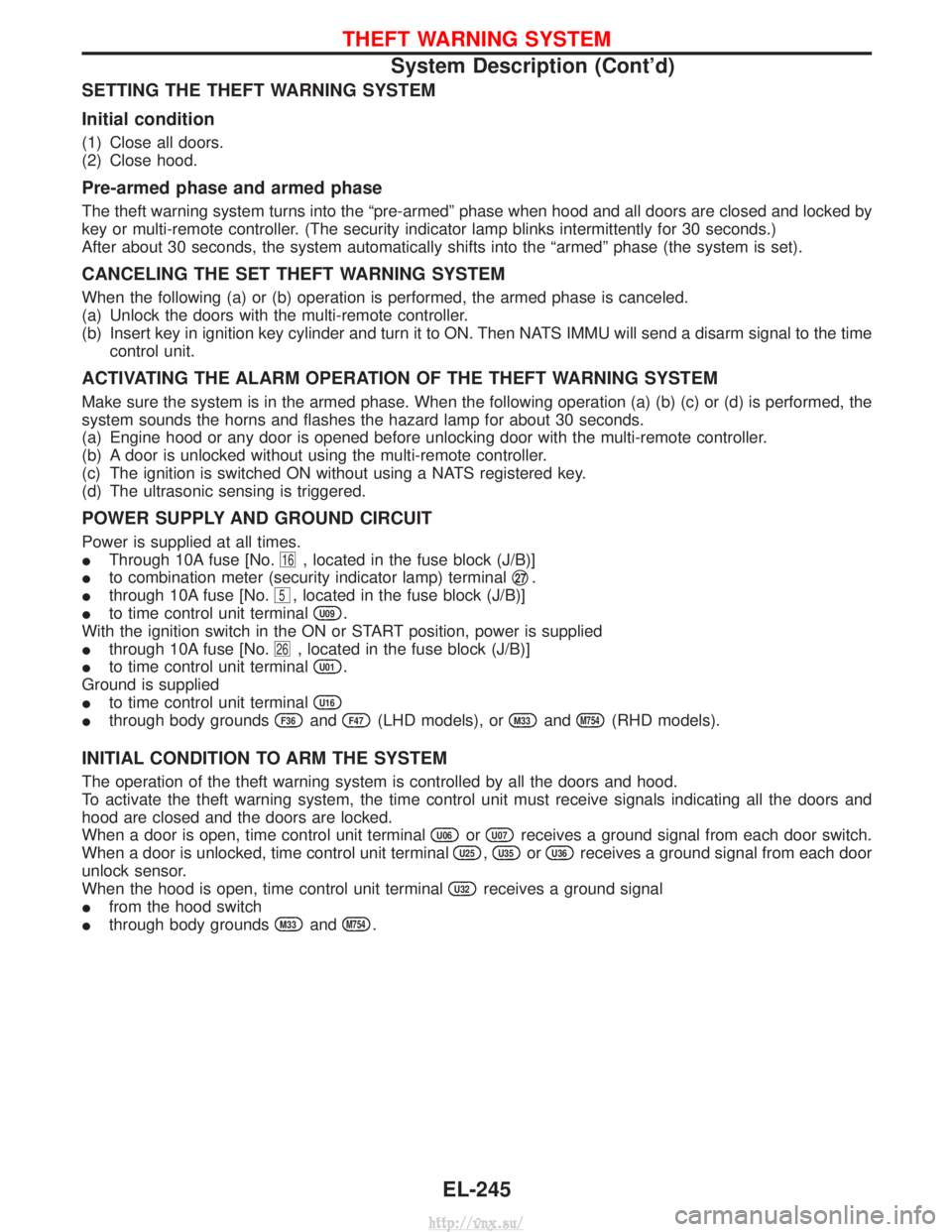
SETTING THE THEFT WARNING SYSTEM
Initial condition
(1) Close all doors.
(2) Close hood.
Pre-armed phase and armed phase
The theft warning system turns into the ªpre-armedº phase when hood and all doors are closed and locked by
key or multi-remote controller. (The security indicator lamp blinks intermittently for 30 seconds.)
After about 30 seconds, the system automatically shifts into the ªarmedº phase (the system is set).
CANCELING THE SET THEFT WARNING SYSTEM
When the following (a) or (b) operation is performed, the armed phase is canceled.
(a) Unlock the doors with the multi-remote controller.
(b) Insert key in ignition key cylinder and turn it to ON. Then NATS IMMU will send a disarm signal to the timecontrol unit.
ACTIVATING THE ALARM OPERATION OF THE THEFT WARNING SYSTEM
Make sure the system is in the armed phase. When the following operation (a) (b) (c) or (d) is performed, the
system sounds the horns and flashes the hazard lamp for about 30 seconds.
(a) Engine hood or any door is opened before unlocking door with the multi-remote controller.
(b) A door is unlocked without using the multi-remote controller.
(c) The ignition is switched ON without using a NATS registered key.
(d) The ultrasonic sensing is triggered.
POWER SUPPLY AND GROUND CIRCUIT
Power is supplied at all times.
IThrough 10A fuse [No.
16, located in the fuse block (J/B)]
I to combination meter (security indicator lamp) terminal q
27.
I through 10A fuse [No.
5, located in the fuse block (J/B)]
I to time control unit terminal
U09.
With the ignition switch in the ON or START position, power is supplied
I through 10A fuse [No.
26, located in the fuse block (J/B)]
I to time control unit terminal
U01.
Ground is supplied
I to time control unit terminal
U16
Ithrough body groundsF36andF47(LHD models), orM33andM754(RHD models).
INITIAL CONDITION TO ARM THE SYSTEM
The operation of the theft warning system is controlled by all the doors and hood.
To activate the theft warning system, the time control unit must receive signals indicating all the doors and
hood are closed and the doors are locked.
When a door is open, time control unit terminal
U06orU07receives a ground signal from each door switch.
When a door is unlocked, time control unit terminal
U25,U35orU36receives a ground signal from each door
unlock sensor.
When the hood is open, time control unit terminal
U32receives a ground signal
I from the hood switch
I through body grounds
M33andM754.
THEFT WARNING SYSTEM
System Description (Cont'd)
EL-245
http://vnx.su/