roof NISSAN TERRANO 2004 Service Repair Manual
[x] Cancel search | Manufacturer: NISSAN, Model Year: 2004, Model line: TERRANO, Model: NISSAN TERRANO 2004Pages: 1833, PDF Size: 53.42 MB
Page 4 of 1833
GENERAL INFORMATIONSECTION
GI
CONTENTS
PRECAUTIONS ...............................................................2
Supplemental Restraint System (SRS) ²AIR
BAG² and²SEAT BELT PRE-TENSIONER²
(Dual Air Bag System) .................................................3
Precautions for NATS ..................................................4
Precautions for Multiport Fuel Injection System
or Engine Control System ...........................................5
Precautions for Catalyst ..............................................5
Precautions for Turbocharger ......................................5
Precautions for Fuel ....................................................6
Precautions for Engine Oils .........................................6
HOW TO USE THIS MANUAL ........................................8
HOW TO READ WIRING DIAGRAMS ..........................10
Sample/Wiring Diagram - EXAMPL - ........................10
Description .................................................................12
HOW TO CHECK TERMINAL .......................................19
How to Probe Connectors .........................................19
How to Check Enlarged Contact Spring of
Terminal .....................................................................20
Waterproof Connector Inspection ..............................21
Terminal Lock Inspection ...........................................21
HOW TO PERFORM EFFICIENT DIAGNOSIS FOR
AN ELECTRICAL INCIDENT ........................................22 Work Flow ..................................................................22
Incident Simulation Tests ...........................................23
HOW TO FOLLOW FLOW CHART IN TROUBLE
DIAGNOSES ..................................................................25
CONSULT-II CHECKING SYSTEM ...............................26
Function and System Application ..............................26
Nickel Metal Hydride Battery Replacement...............26
Checking Equipment..................................................26
IDENTIFICATION INFORMATION .................................27
Model Variation ..........................................................27
Identification Number .................................................28
Dimensions ................................................................30
Wheels and Tires .......................................................30
LIFTING POINTS AND TOW TRUCK TOWING ...........31
Garage Jack and Safety Stand .................................31
Screw Jack ................................................................31
4-pole Lift ...................................................................32
Tow Truck Towing ......................................................32
ISO 15031-2 TERMINOLOGY LIST ..............................34
ISO 15031-2 Terminology List ...................................34
TIGHTENING TORQUE OF STANDARD BOLTS ........37
http://vnx.su/
Page 22 of 1833
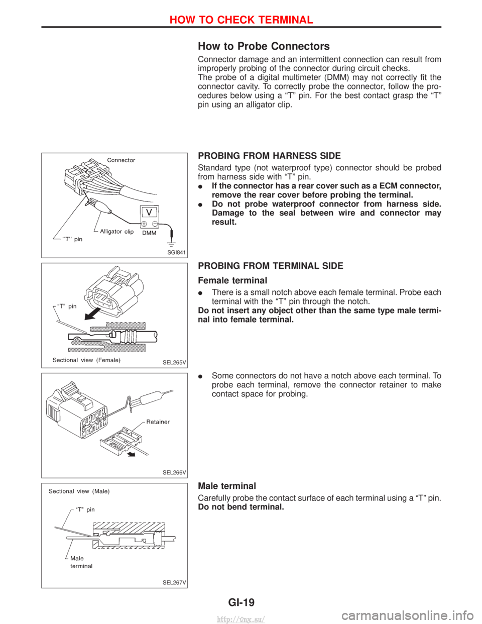
How to Probe Connectors
Connector damage and an intermittent connection can result from
improperly probing of the connector during circuit checks.
The probe of a digital multimeter (DMM) may not correctly fit the
connector cavity. To correctly probe the connector, follow the pro-
cedures below using a ªTº pin. For the best contact grasp the ªTº
pin using an alligator clip.
PROBING FROM HARNESS SIDE
Standard type (not waterproof type) connector should be probed
from harness side with ªTº pin.
IIf the connector has a rear cover such as a ECM connector,
remove the rear cover before probing the terminal.
I Do not probe waterproof connector from harness side.
Damage to the seal between wire and connector may
result.
PROBING FROM TERMINAL SIDE
Female terminal
IThere is a small notch above each female terminal. Probe each
terminal with the ªTº pin through the notch.
Do not insert any object other than the same type male termi-
nal into female terminal.
I Some connectors do not have a notch above each terminal. To
probe each terminal, remove the connector retainer to make
contact space for probing.
Male terminal
Carefully probe the contact surface of each terminal using a ªTº pin.
Do not bend terminal.
SGI841
SEL265V
SEL266V
SEL267V
HOW TO CHECK TERMINAL
GI-19
http://vnx.su/
Page 24 of 1833
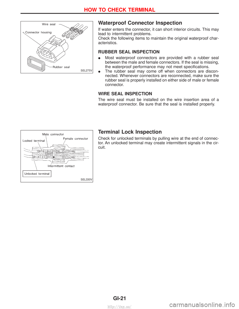
Waterproof Connector Inspection
If water enters the connector, it can short interior circuits. This may
lead to intermittent problems.
Check the following items to maintain the original waterproof char-
acteristics.
RUBBER SEAL INSPECTION
IMost waterproof connectors are provided with a rubber seal
between the male and female connectors. If the seal is missing,
the waterproof performance may not meet specifications.
I The rubber seal may come off when connectors are discon-
nected. Whenever connectors are reconnected, make sure the
rubber seal is properly installed on either side of male or female
connector.
WIRE SEAL INSPECTION
The wire seal must be installed on the wire insertion area of a
waterproof connector. Be sure that the seal is installed properly.
Terminal Lock Inspection
Check for unlocked terminals by pulling wire at the end of connec-
tor. An unlocked terminal may create intermittent signals in the cir-
cuit.
SEL275V
SEL330V
HOW TO CHECK TERMINAL
GI-21
http://vnx.su/
Page 88 of 1833
Checking Body Corrosion
Visually check the body sheet metal panel for corrosion, paint damage (scratches, chipping, rubbing, etc.) or
damage to the anti-corrosion materials. In particular, check the following locations.
Hemmed portion
Hood front end, door lower end, trunk lid rear end, etc.
Panel joint
Side sill of rear fender and center pillar, rear wheel housing of rear fender, around strut lower in engine
compartment, etc.
Panel edge
Back door lid opening, sun roof opening, fender wheel-arch flange, fuel filler lid flange, around holes in panel,
etc.
Parts contact
Waist moulding, windshield moulding, bumper, etc.
Protectors
Damage or condition of mudguard, fender protector, chipping protector, etc.
Anti-corrosion materials
Damage or separation of anti-corrosion materials under the body.
Drain holes
Condition of drain holes at door and side sill.
When repairing corroded areas, refer to the Corrosion Repair Manual.
CHASSIS AND BODY MAINTENANCE
MA-47
http://vnx.su/
Page 758 of 1833
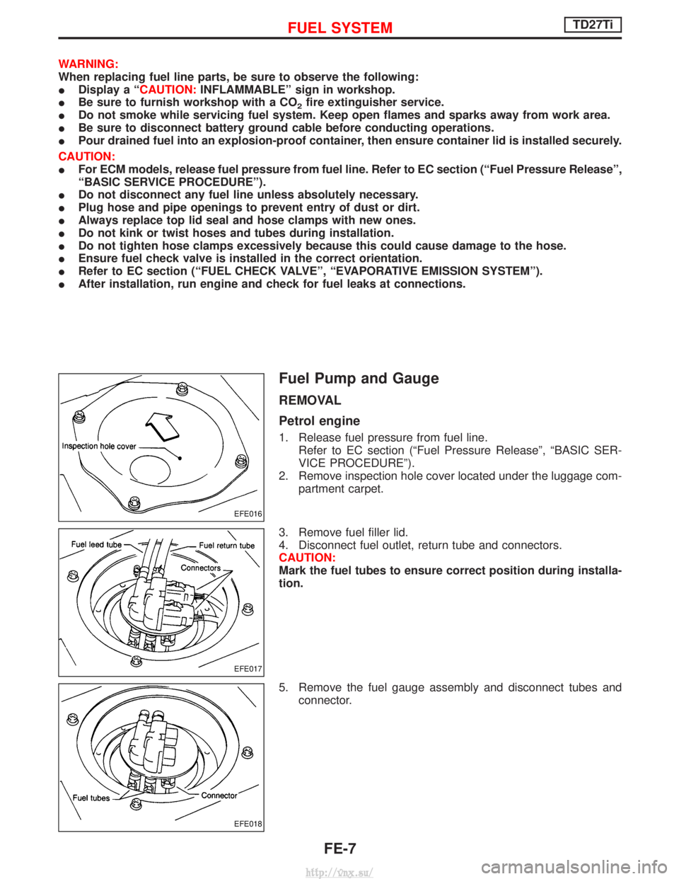
WARNING:
When replacing fuel line parts, be sure to observe the following:
IDisplay a ªCAUTION: INFLAMMABLEº sign in workshop.
I Be sure to furnish workshop with a CO
2fire extinguisher service.
I Do not smoke while servicing fuel system. Keep open flames and sparks away from work area.
I Be sure to disconnect battery ground cable before conducting operations.
I Pour drained fuel into an explosion-proof container, then ensure container lid is installed securely.
CAUTION:
I For ECM models, release fuel pressure from fuel line. Refer to EC section (ªFuel Pressure Releaseº,
ªBASIC SERVICE PROCEDUREº).
I Do not disconnect any fuel line unless absolutely necessary.
I Plug hose and pipe openings to prevent entry of dust or dirt.
I Always replace top lid seal and hose clamps with new ones.
I Do not kink or twist hoses and tubes during installation.
I Do not tighten hose clamps excessively because this could cause damage to the hose.
I Ensure fuel check valve is installed in the correct orientation.
I Refer to EC section (ªFUEL CHECK VALVEº, ªEVAPORATIVE EMISSION SYSTEMº).
I After installation, run engine and check for fuel leaks at connections.
Fuel Pump and Gauge
REMOVAL
Petrol engine
1. Release fuel pressure from fuel line.
Refer to EC section (ªFuel Pressure Releaseº, ªBASIC SER-
VICE PROCEDUREº).
2. Remove inspection hole cover located under the luggage com- partment carpet.
3. Remove fuel filler lid.
4. Disconnect fuel outlet, return tube and connectors.
CAUTION:
Mark the fuel tubes to ensure correct position during installa-
tion.
5. Remove the fuel gauge assembly and disconnect tubes and connector.
EFE016
EFE017
EFE018
FUEL SYSTEMTD27Ti
FE-7
http://vnx.su/
Page 1338 of 1833
BODY & TRIM
SECTION
BT
CONTENTS
PRECAUTIONS ...............................................................2
Service Notice..............................................................2
Supplemental Restraint System (SRS) ²AIR
BAG² and²SEAT BELT PRE-TENSIONER² ...............2
CLIP AND FASTENER ....................................................3
Description ...................................................................3
CHASSIS AND BODY MAINTENANCE .........................5
Checking Body Corrosion ............................................5
BODY FRONT END .........................................................6
Removal and Installation .............................................6
BODY REAR END AND OPENER ..................................8
Removal and Installation .............................................8
DOOR ........................................................................\
.....10
Removal and Installation ...........................................10
INSTRUMENT PANEL ASSEMBLY ..............................16
Removal and Installation ...........................................16
SIDE AND FLOOR TRIM ..............................................18
Removal and Installation ...........................................18
DOOR TRIM ...................................................................19
Removal and Installation ...........................................19 ROOF TRIM
...................................................................20
Removal and Installation ...........................................20
EXTERIOR .....................................................................21
Removal and Installation ...........................................21
FRONT SEAT .................................................................34
Removal and Installation ...........................................34
Heated Seat ...............................................................36
Active Head Restraint ................................................36
SECOND SEAT ..............................................................37
Removal and Installation ...........................................37
THIRD SEAT ..................................................................39
Removal and Installation ...........................................39
SUNROOF ......................................................................40
Removal and Installation ...........................................40
WINDSHIELD AND WINDOWS ....................................42
Removal and Installation ...........................................42
DOOR MIRROR .............................................................48
Removal and Installation ...........................................48
BODY (ALIGNMENT) ....................................................49
Alignment ...................................................................49
http://vnx.su/
Page 1342 of 1833
Checking Body Corrosion
Visually check the body sheet metal panel for corrosion, paint damage (scratches, chipping, rubbing, etc.) or
damage to the anti-corrosion materials. In particular, check the following locations.
Hemmed portion
Hood front end, door lower end, back door rear end, etc.
Panel joint
Side sill of rear fender and center pillar, rear wheel housing of rear fender, around strut tower in engine
compartment, etc.
Panel edge
Back door opening, sunroof opening, fender wheelarch flange, fuel filler lid flange, around holes in panel, etc.
Parts contact
Waist molding, windshield molding, bumper, etc.
Protectors
Damage or condition of mudguard, fender protector, chipping protector, etc.
Anti-corrosion materials
Damage or separation of anti-corrosion materials under the body.
Drain holes
Condition of drain holes at door and side sill.
When repairing corroded areas, refer to the Corrosion Repair Manual.
CHASSIS AND BODY MAINTENANCE
BT-5
http://vnx.su/
Page 1357 of 1833
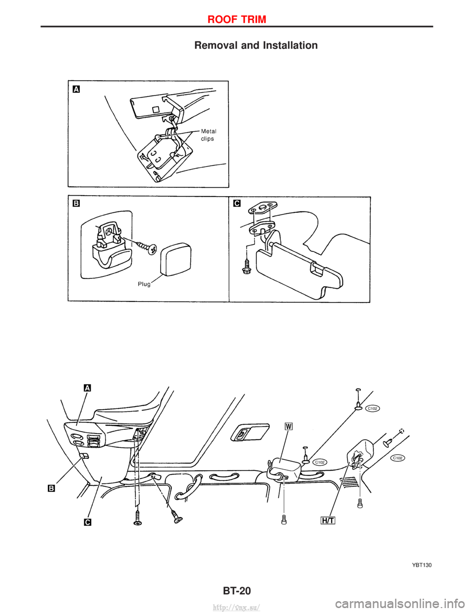
Removal and Installation
YBT130
ROOF TRIM
BT-20
http://vnx.su/
Page 1377 of 1833
Removal and Installation
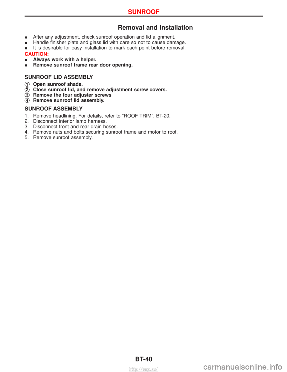
IAfter any adjustment, check sunroof operation and lid alignment.
I Handle finisher plate and glass lid with care so not to cause damage.
I It is desirable for easy installation to mark each point before removal.
CAUTION:
I Always work with a helper.
I Remove sunroof frame rear door opening.
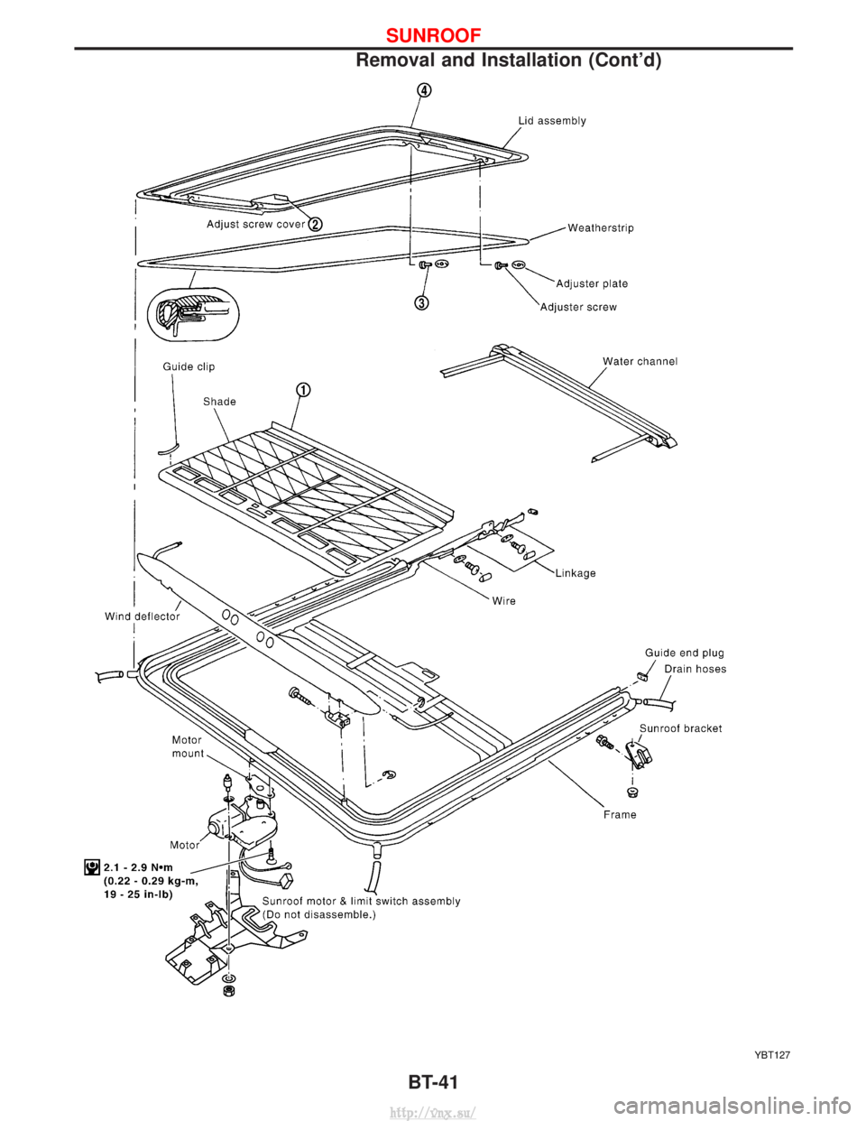
SUNROOF LID ASSEMBLY
q1Open sunroof shade.
q
2Close sunroof lid, and remove adjustment screw covers.
q
3Remove the four adjuster screws
q
4Remove sunroof lid assembly.
SUNROOF ASSEMBLY
1. Remove headlining. For details, refer to ªROOF TRIMº, BT-20.
2. Disconnect interior lamp harness.
3. Disconnect front and rear drain hoses.
4. Remove nuts and bolts securing sunroof frame and motor to roof.
5. Remove sunroof assembly.
SUNROOF
BT-40
http://vnx.su/
Page 1378 of 1833
YBT127
SUNROOF
Removal and Installation (Cont'd)BT-41
http://vnx.su/