set clock NISSAN TERRANO 2004 Service Repair Manual
[x] Cancel search | Manufacturer: NISSAN, Model Year: 2004, Model line: TERRANO, Model: NISSAN TERRANO 2004Pages: 1833, PDF Size: 53.42 MB
Page 118 of 1833

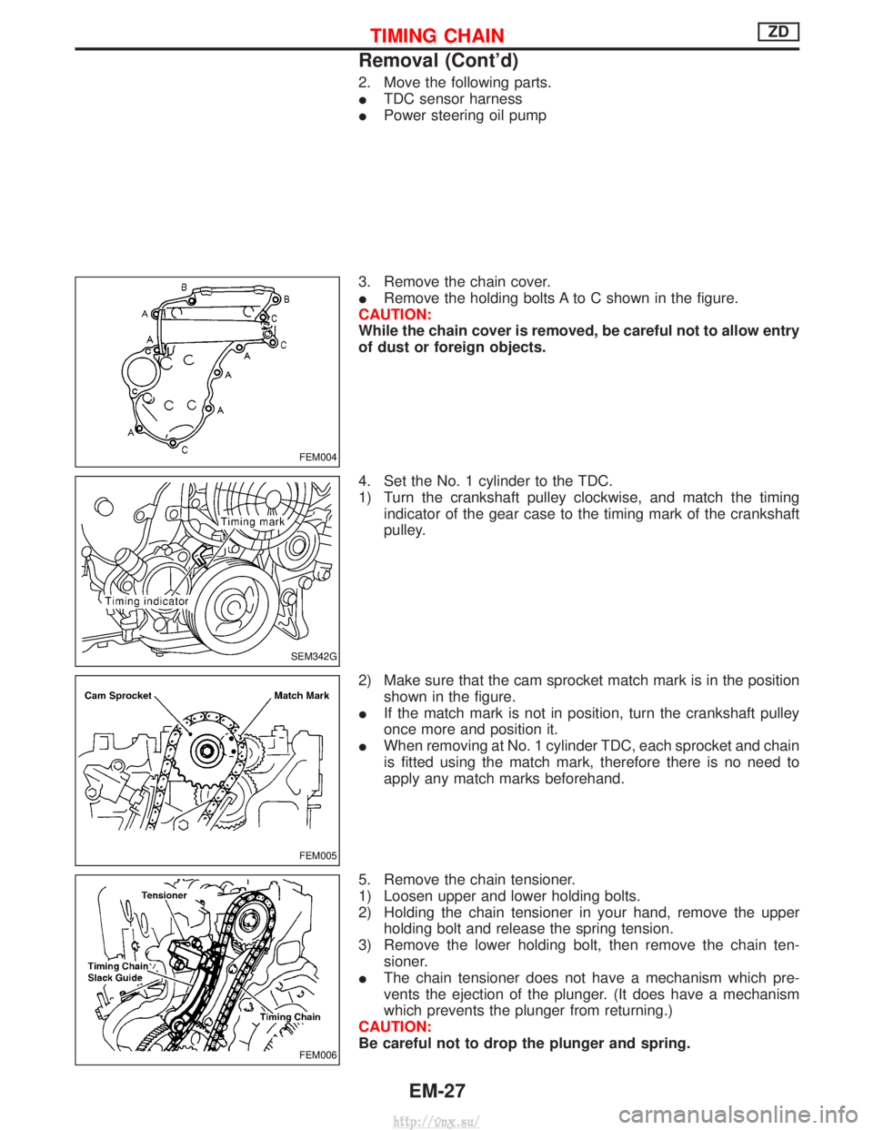
2. Move the following parts.
ITDC sensor harness
I Power steering oil pump
3. Remove the chain cover.
I Remove the holding bolts A to C shown in the figure.
CAUTION:
While the chain cover is removed, be careful not to allow entry
of dust or foreign objects.
4. Set the No. 1 cylinder to the TDC.
1) Turn the crankshaft pulley clockwise, and match the timing indicator of the gear case to the timing mark of the crankshaft
pulley.
2) Make sure that the cam sprocket match mark is in the position shown in the figure.
I If the match mark is not in position, turn the crankshaft pulley
once more and position it.
I When removing at No. 1 cylinder TDC, each sprocket and chain
is fitted using the match mark, therefore there is no need to
apply any match marks beforehand.
5. Remove the chain tensioner.
1) Loosen upper and lower holding bolts.
2) Holding the chain tensioner in your hand, remove the upper holding bolt and release the spring tension.
3) Remove the lower holding bolt, then remove the chain ten- sioner.
I The chain tensioner does not have a mechanism which pre-
vents the ejection of the plunger. (It does have a mechanism
which prevents the plunger from returning.)
CAUTION:
Be careful not to drop the plunger and spring.
FEM004
SEM342G
FEM005
FEM006
TIMING CHAINZD
Removal (Cont'd)
EM-27
http://vnx.su/
Page 126 of 1833

Inspection
IWhen the camshaft or parts in connection with valves are
removed or replaced, and a fault has occurred (poor starting,
idling, or other faults) due to the misadjustment of the valve
clearance, inspect as follows.
I Inspect and adjust when the engine is cool (at normal tempera-
ture).
I Be careful of the intake and exhaust valve arrangement. (The
valve arrangement is different from that in a normal engine.)
(The camshafts have, alternately, either an intake valve or an
exhaust valve.)
1. Remove the following parts.
I Intercooler cover
I Intercooler
I Rocker cover
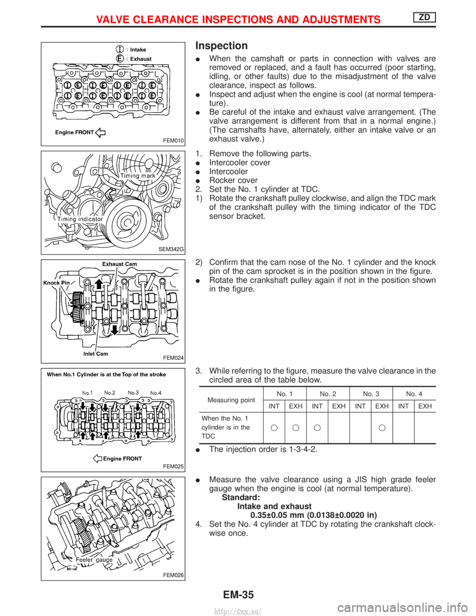
2. Set the No. 1 cylinder at TDC.
1) Rotate the crankshaft pulley clockwise, and align the TDC mark of the crankshaft pulley with the timing indicator of the TDC
sensor bracket.
2) Confirm that the cam nose of the No. 1 cylinder and the knock pin of the cam sprocket is in the position shown in the figure.
I Rotate the crankshaft pulley again if not in the position shown
in the figure.
3. While referring to the figure, measure the valve clearance in the circled area of the table below.
Measuring point No. 1 No. 2 No. 3 No. 4
INT EXH INT EXH INT EXH INT EXH
When the No. 1
cylinder is in the
TDC qqq q
I
The injection order is 1-3-4-2.
I Measure the valve clearance using a JIS high grade feeler
gauge when the engine is cool (at normal temperature).
Standard: Intake and exhaust0.35 0.05 mm (0.0138 0.0020 in)
4. Set the No. 4 cylinder at TDC by rotating the crankshaft clock- wise once.
FEM010
SEM342G
FEM024
FEM025
FEM026
VALVE CLEARANCE INSPECTIONS AND ADJUSTMENTSZD
EM-35
http://vnx.su/
Page 637 of 1833

qA
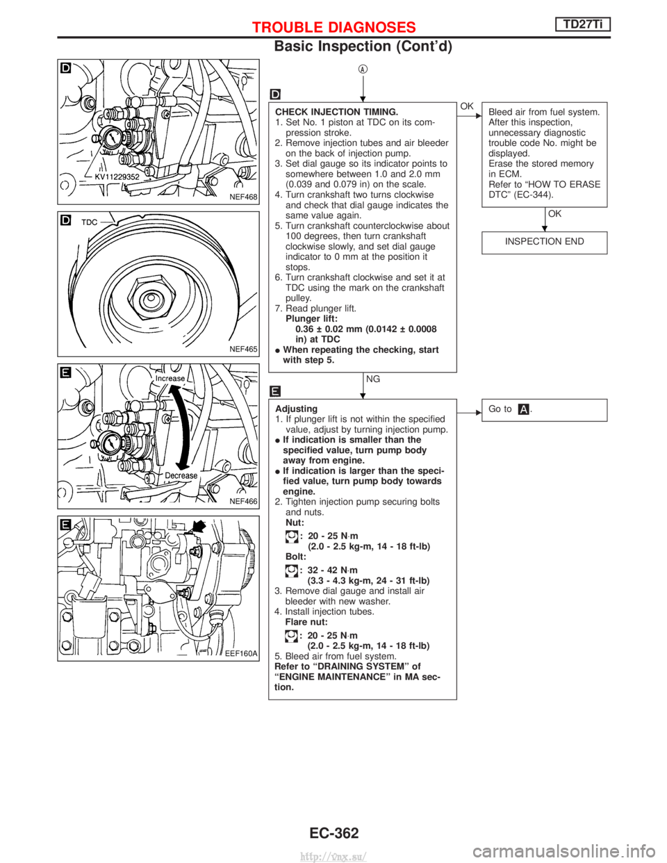
CHECK INJECTION TIMING.
1. Set No. 1 piston at TDC on its com-pression stroke.
2. Remove injection tubes and air bleeder on the back of injection pump.
3. Set dial gauge so its indicator points to somewhere between 1.0 and 2.0 mm
(0.039 and 0.079 in) on the scale.
4. Turn crankshaft two turns clockwise and check that dial gauge indicates the
same value again.
5. Turn crankshaft counterclockwise about 100 degrees, then turn crankshaft
clockwise slowly, and set dial gauge
indicator to 0 mm at the position it
stops.
6. Turn crankshaft clockwise and set it at TDC using the mark on the crankshaft
pulley.
7. Read plunger lift. Plunger lift:0.36 0.02 mm (0.0142 0.0008
in) at TDC
I When repeating the checking, start
with step 5.
NG
EOK
Bleed air from fuel system.
After this inspection,
unnecessary diagnostic
trouble code No. might be
displayed.
Erase the stored memory
in ECM.
Refer to ªHOW TO ERASE
DTCº (EC-344).
OK
INSPECTION END
Adjusting
1. If plunger lift is not within the specified value, adjust by turning injection pump.
I If indication is smaller than the
specified value, turn pump body
away from engine.
I If indication is larger than the speci-
fied value, turn pump body towards
engine.
2. Tighten injection pump securing bolts and nuts.
Nut:
: 20-25N ×m
(2.0 - 2.5 kg-m, 14 - 18 ft-lb)
Bolt:
: 32-42N ×m
(3.3 - 4.3 kg-m, 24 - 31 ft-lb)
3. Remove dial gauge and install air bleeder with new washer.
4. Install injection tubes. Flare nut:
: 20-25N ×m
(2.0 - 2.5 kg-m, 14 - 18 ft-lb)
5. Bleed air from fuel system.
Refer to ªDRAINING SYSTEMº of
ªENGINE MAINTENANCEº in MA sec-
tion.
EGo to.
NEF468
NEF465
NEF466
EEF160A
H
H
H
TROUBLE DIAGNOSESTD27Ti
Basic Inspection (Cont'd)
EC-362
http://vnx.su/
Page 1293 of 1833

4. Set steering wheel in the neutral position.
5. Disconnect horn connector (or horn/audio connector) andremove nut.
6. Remove steering wheel.
CAUTION:
I Do not tap or bump the steering wheel.
7. Remove steering column cover.
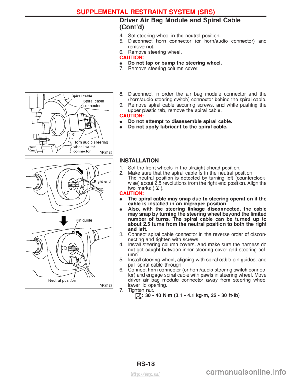
8. Disconnect in order the air bag module connector and the (horn/audio steering switch) connector behind the spiral cable.
9. Remove spiral cable securing screws, and while pushing the upper plastic tab, remove the spiral cable.
CAUTION:
I Do not attempt to disassemble spiral cable.
I Do not apply lubricant to the spiral cable.
INSTALLATION
1. Set the front wheels in the straight-ahead position.
2. Make sure that the spiral cable is in the neutral position.
The neutral position is detected by turning left (counterclock-
wise) about 2.5 revolutions from the right end position. Align the
two marks (
).
CAUTION:
I The spiral cable may snap due to steering operation if the
cable is installed in an improper position.
I Also, with the steering linkage disconnected, the cable
may snap by turning the steering wheel beyond the limited
number of turns. The spiral cable can be turned up to
about 2.5 turns from the neutral position to both the right
and left.
3. Connect spiral cable connector in the reverse order of discon- necting and tighten with screws.
4. Install steering column covers. And make sure the harness do not get caught between inner steering cover and steering col-
umn.
5. Install steering wheel, aligning with spiral cable pin guides, and pull spiral cable through.
6. Connect horn connector (or horn/audio steering switch connec- tor) and engage spiral cable with pawls in steering wheel. Move
driver air bag module connector away from steering wheel
lower lid opening.
7. Tighten nut.
:30-40N ×m (3.1 - 4.1 kg-m, 22 - 30 ft-lb)
YRS125
YRS123
SUPPLEMENTAL RESTRAINT SYSTEM (SRS)
Driver Air Bag Module and Spiral Cable
(Cont'd)
RS-18
http://vnx.su/