steering wheel adjustment NISSAN TERRANO 2004 Service Repair Manual
[x] Cancel search | Manufacturer: NISSAN, Model Year: 2004, Model line: TERRANO, Model: NISSAN TERRANO 2004Pages: 1833, PDF Size: 53.42 MB
Page 12 of 1833
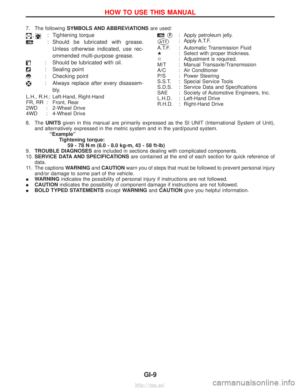
7. The followingSYMBOLS AND ABBREVIATIONS are used:
,: Tightening torque
: Should be lubricated with grease.
Unless otherwise indicated, use rec-
ommended multi-purpose grease.
: Should be lubricated with oil.
: Sealing point
: Checking point
: Always replace after every disassem- bly.
L.H., R.H.: Left-Hand, Right-Hand
FR, RR : Front, Rear
2WD : 2-Wheel Drive
4WD : 4-Wheel Drive
qP: Apply petroleum jelly.
: Apply A.T.F.
A.T.F. : Automatic Transmission Fluid
H : Select with proper thickness.
I : Adjustment is required.
M/T : Manual Transaxle/Transmission
A/C : Air Conditioner
P/S : Power Steering
S.S.T. : Special Service Tools
S.D.S. : Service Data and Specifications
SAE : Society of Automotive Engineers, Inc.
L.H.D. : Left-Hand Drive
R.H.D. : Right-Hand Drive
8. The UNITSgiven in this manual are primarily expressed as the SI UNIT (International System of Unit),
and alternatively expressed in the metric system and in the yard/pound system. ªExampleºTightening torque:59-78N ×m (6.0 - 8.0 kg-m, 43 - 58 ft-lb)
9. TROUBLE DIAGNOSES are included in sections dealing with complicated components.
10. SERVICE DATA AND SPECIFICATIONS are contained at the end of each section for quick reference of
data.
11. The captions WARNINGandCAUTION warn you of steps that must be followed to prevent personal injury
and/or damage to some part of the vehicle.
I WARNING indicates the possibility of personal injury if instructions are not followed.
I CAUTION indicates the possibility of component damage if instructions are not followed.
I BOLD TYPED STATEMENTS exceptWARNING andCAUTION give you helpful information.
HOW TO USE THIS MANUAL
GI-9
http://vnx.su/
Page 90 of 1833
Chassis and Body Maintenance
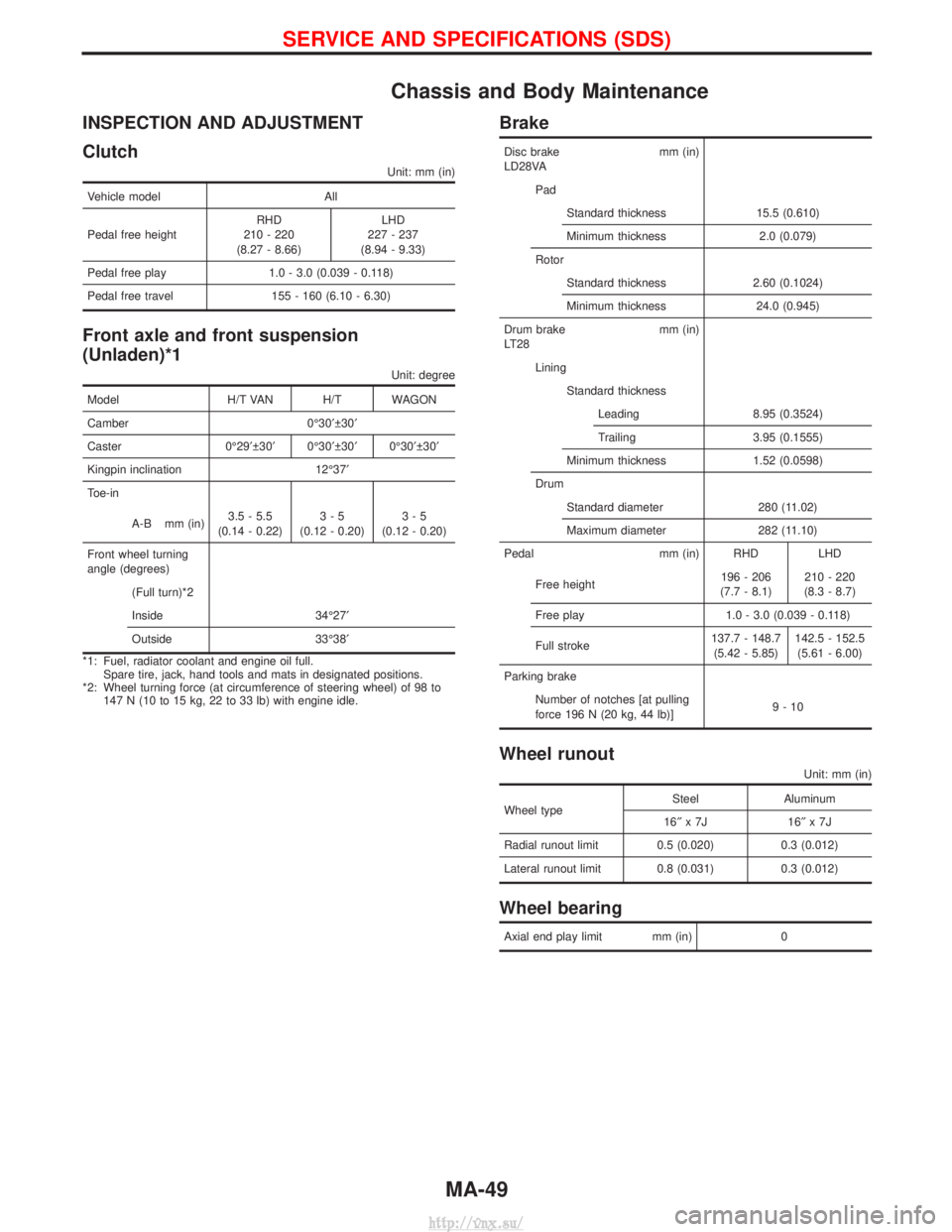
INSPECTION AND ADJUSTMENT
Clutch
Unit: mm (in)
Vehicle modelAll
Pedal free height RHD
210 - 220
(8.27 - 8.66) LHD
227 - 237
(8.94 - 9.33)
Pedal free play 1.0 - 3.0 (0.039 - 0.118)
Pedal free travel 155 - 160 (6.10 - 6.30)
Front axle and front suspension
(Unladen)*1
Unit: degree
Model H/T VAN H/T WAGON
Camber 0É30¢ 30¢
Caster 0É29¢ 30¢ 0É30¢ 30¢ 0É30¢ 30¢
Kingpin inclination 12É37¢
Toe-in
A-B mm (in) 3.5 - 5.5
(0.14 - 0.22) 3-5
(0.12 - 0.20) 3-5
(0.12 - 0.20)
Front wheel turning
angle (degrees) (Full turn)*2
Inside 34É27¢
Outside 33É38¢
*1: Fuel, radiator coolant and engine oil full. Spare tire, jack, hand tools and mats in designated positions.
*2: Wheel turning force (at circumference of steering wheel) of 98 to 147 N (10 to 15 kg, 22 to 33 lb) with engine idle.
Brake
Disc brake mm (in)
LD28VA
PadStandard thickness 15.5 (0.610)
Minimum thickness 2.0 (0.079)
Rotor Standard thickness 2.60 (0.1024)
Minimum thickness 24.0 (0.945)
Drum brake mm (in)
LT28 LiningStandard thicknessLeading 8.95 (0.3524)
Trailing 3.95 (0.1555)
Minimum thickness 1.52 (0.0598)
Drum Standard diameter 280 (11.02)
Maximum diameter 282 (11.10)
Pedal mm (in) RHD LHD
Free height 196 - 206
(7.7 - 8.1) 210 - 220
(8.3 - 8.7)
Free play 1.0 - 3.0 (0.039 - 0.118)
Full stroke 137.7 - 148.7
(5.42 - 5.85) 142.5 - 152.5
(5.61 - 6.00)
Parking brake Number of notches [at pulling
force 196 N (20 kg, 44 lb)] 9-10
Wheel runout
Unit: mm (in)
Wheel typeSteel Aluminum
16² x7J 16 ²x7J
Radial runout limit 0.5 (0.020) 0.3 (0.012)
Lateral runout limit 0.8 (0.031) 0.3 (0.012)
Wheel bearing
Axial end play limit mm (in) 0
SERVICE AND SPECIFICATIONS (SDS)
MA-49
http://vnx.su/
Page 1119 of 1833
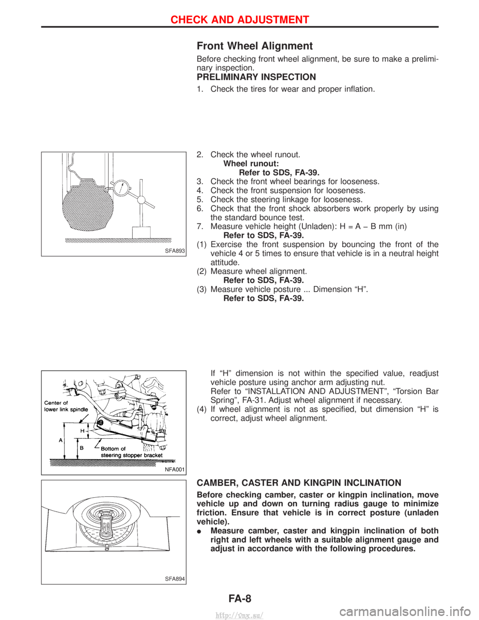
Front Wheel Alignment
Before checking front wheel alignment, be sure to make a prelimi-
nary inspection.
PRELIMINARY INSPECTION
1. Check the tires for wear and proper inflation.
2. Check the wheel runout.Wheel runout:Refer to SDS, FA-39.
3. Check the front wheel bearings for looseness.
4. Check the front suspension for looseness.
5. Check the steering linkage for looseness.
6. Check that the front shock absorbers work properly by using the standard bounce test.
7. Measure vehicle height (Unladen): H = A þ B mm (in) Refer to SDS, FA-39.
(1) Exercise the front suspension by bouncing the front of the vehicle 4 or 5 times to ensure that vehicle is in a neutral height
attitude.
(2) Measure wheel alignment. Refer to SDS, FA-39.
(3) Measure vehicle posture ... Dimension ªHº. Refer to SDS, FA-39.
If ªHº dimension is not within the specified value, readjust
vehicle posture using anchor arm adjusting nut.
Refer to ªINSTALLATION AND ADJUSTMENTº, ªTorsion Bar
Springº, FA-31. Adjust wheel alignment if necessary.
(4) If wheel alignment is not as specified, but dimension ªHº is correct, adjust wheel alignment.
CAMBER, CASTER AND KINGPIN INCLINATION
Before checking camber, caster or kingpin inclination, move
vehicle up and down on turning radius gauge to minimize
friction. Ensure that vehicle is in correct posture (unladen
vehicle).
IMeasure camber, caster and kingpin inclination of both
right and left wheels with a suitable alignment gauge and
adjust in accordance with the following procedures.
SFA893
NFA001
SFA894
CHECK AND ADJUSTMENT
FA-8
http://vnx.su/
Page 1122 of 1833
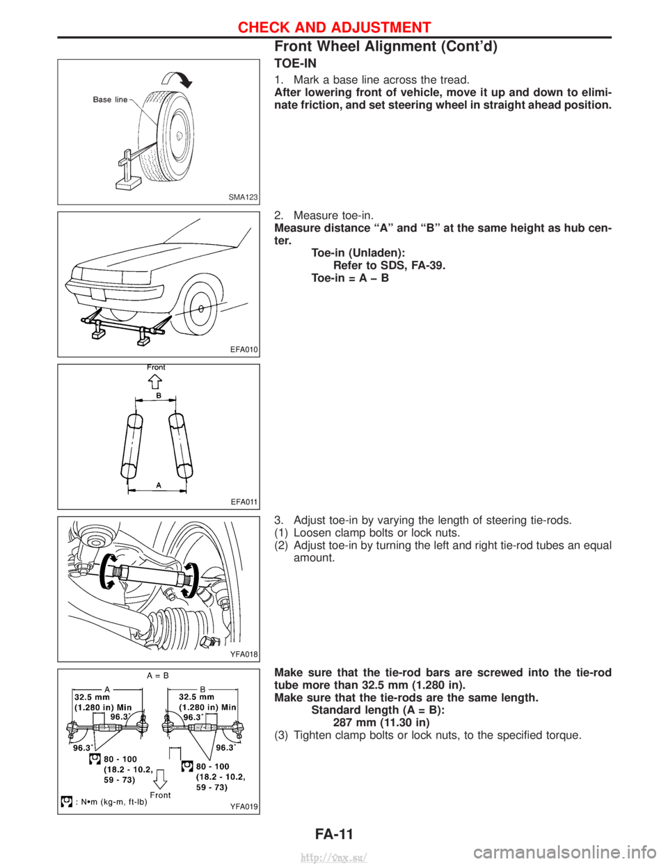
TOE-IN
1. Mark a base line across the tread.
After lowering front of vehicle, move it up and down to elimi-
nate friction, and set steering wheel in straight ahead position.
2. Measure toe-in.
Measure distance ªAº and ªBº at the same height as hub cen-
ter.Toe-in (Unladen):Refer to SDS, FA-39.
Toe-in = A þ B
3. Adjust toe-in by varying the length of steering tie-rods.
(1) Loosen clamp bolts or lock nuts.
(2) Adjust toe-in by turning the left and right tie-rod tubes an equal amount.
Make sure that the tie-rod bars are screwed into the tie-rod
tube more than 32.5 mm (1.280 in).
Make sure that the tie-rods are the same length. Standard length (A = B):287 mm (11.30 in)
(3) Tighten clamp bolts or lock nuts, to the specified torque.
SMA123
EFA010
EFA011
YFA018
YFA019
CHECK AND ADJUSTMENT
Front Wheel Alignment (Cont'd)
FA-11
http://vnx.su/
Page 1123 of 1833
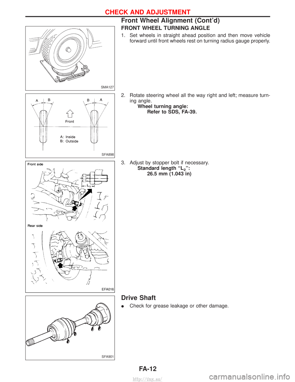
FRONT WHEEL TURNING ANGLE
1. Set wheels in straight ahead position and then move vehicleforward until front wheels rest on turning radius gauge properly.
2. Rotate steering wheel all the way right and left; measure turn- ing angle.Wheel turning angle: Refer to SDS, FA-39.
3. Adjust by stopper bolt if necessary. Standard length ªL
2º:
26.5 mm (1.043 in)
Drive Shaft
I Check for grease leakage or other damage.
SMA127
SFA898
EFA016
SFA901
CHECK AND ADJUSTMENT
Front Wheel Alignment (Cont'd)
FA-12
http://vnx.su/
Page 1170 of 1833
Supplement Restraint System (SRS) ªAIR BAGº
and ªSEAT BELT PRE-TENSIONERº
The Supplemental Restraint System ªAir Bagº and ªSeat Belt Pre-tensionerº, used along with a seat belt, help
to reduce the risk or severity or injury to the driver and front passenger in a collision. The Supplemental
Restraint System consists of an air bag module (located in the center of the steering wheel and on the instru-
ment panel on the passenger side, where fitted), seat belt pre-tensioners, a diagnosis sensor unit, warning
lamp, wiring harness and spiral cable. Information necessary to service the system safely is included in the
BT sectionof this Service Manual.
WARNING:
I To avoid rendering the SRS inoperative (which could increase the risk of personal injury or death
in the event of a collision which would result in air bag inflation), all maintenance must be per-
formed by an authorized NISSAN dealer.
I Improper maintenance, including incorrect removal and installation of the SRS, can lead to per-
sonal injury caused by unintentional activation of the system.
I Do not use electrical test equipment on any circuit related to the SRS unless instructed to in this
Service Manual. SRS wiring harnesses (except ªSEAT BELT-TENSIONERº connector) can be iden-
tified with yellow harness connector and with yellow harness protector or yellow insulation tape
before the harness connectors.
Precautions
IUse only ªDOT 4º fluid from a sealed container.
I Never reuse drained brake fluid.
I Be careful not to splash brake fluid on painted areas; it
may cause paint damage. If brake fluid is splashed on
painted areas, wash it away with water immediately.
I To clean master cylinder parts, disc brake caliper parts or
wheel cylinder parts, use clean brake fluid.
I Never use mineral oils such as Petrol or kerosene. They
will ruin rubber parts of hydraulic system.
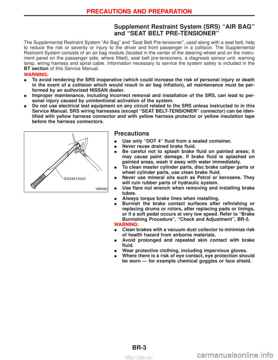
I Use flare nut wrench when removing and installing brake
tubes.
I Always torque brake lines when installing.
I Burnish the brake contact surfaces after refinishing or
replacing drums or rotors, after replacing pads or linings,
or if a soft pedal occurs at very low speed. Refer to ªBrake
Burnishing Procedureº, ªCheck and Adjustmentº, BR-5.
WARNING:
I Clean brakes with a vacuum dust collector to minimize risk
of health hazard from airborne materials.
I Avoid prolonged and repeated skin contact with brake
fluid.
I Wear protective clothing, including impervious gloves.
I Where there is a risk of eye contact, eye protection should
be worn Ð for example chemical goggles or face shield.
YBR293
PRECAUTIONS AND PREPARATION
BR-3
http://vnx.su/
Page 1254 of 1833
STEERING SYSTEM
SECTION
ST
CONTENTS
PRECAUTIONS ...............................................................2
Supplemental Restraint System (SRS) ²AIR
BAG² and²SEAT BELT PRE-TENSIONER² ...............2
Precautions for SRS ²AIR BAG² and²SEAT
BELT PRE-TENSIONER² Service ...............................2
Precautions for Steering System .................................2
PREPARATION ................................................................3
Special Service Tools ..................................................3
ON-VEHICLE SERVICE ..................................................4
Checking Steering Wheel Play ....................................4
Checking Neutral Position on Steering Wheel ............4
Front Wheel Turning Angle ..........................................4
Checking and Adjusting Drive Belts ............................4
Checking Fluid Level ...................................................4
Checking Fluid Leakage ..............................................5
Bleeding Hydraulic System..........................................5
Checking Steering Wheel Turning Force ....................6
Checking Hydraulic System.........................................7 STEERING WHEEL AND STEERING COLUMN
............8
Removal and Installation .............................................8
Disassembly and Assembly .......................................10
Inspection................................................................... 11
POWER STEERING GEAR ...........................................12
Description .................................................................12
Removal and Installation ...........................................14
Inspection and Adjustment ........................................15
POWER STEERING OIL PUMP ....................................16
Removal and Installation ...........................................16
STEERING LINKAGE ....................................................17
Removal and Installation ...........................................17
Disassembly and Assembly .......................................19
Inspection...................................................................20
SERVICE DATA AND SPECIFICATIONS (SDS) ..........22
General Specifications ...............................................22
Inspection and Adjustment ........................................22
http://vnx.su/
Page 1259 of 1833
Checking Steering Wheel Turning Force
1. Park vehicle on a level, dry surface and set parking brake.
2. Start engine.
3. Bring power steering fluid up to adequate operating tempera-ture.Temperature: 50É - 80ÉC (122 - 176ÉF)
Tires need to be inflated to normal pressure.
4. Check steering wheel turning force when steering wheel has been turned 360É from neutral position.Steering wheel turning force: 39 N (4 kg, 9 lb) or less
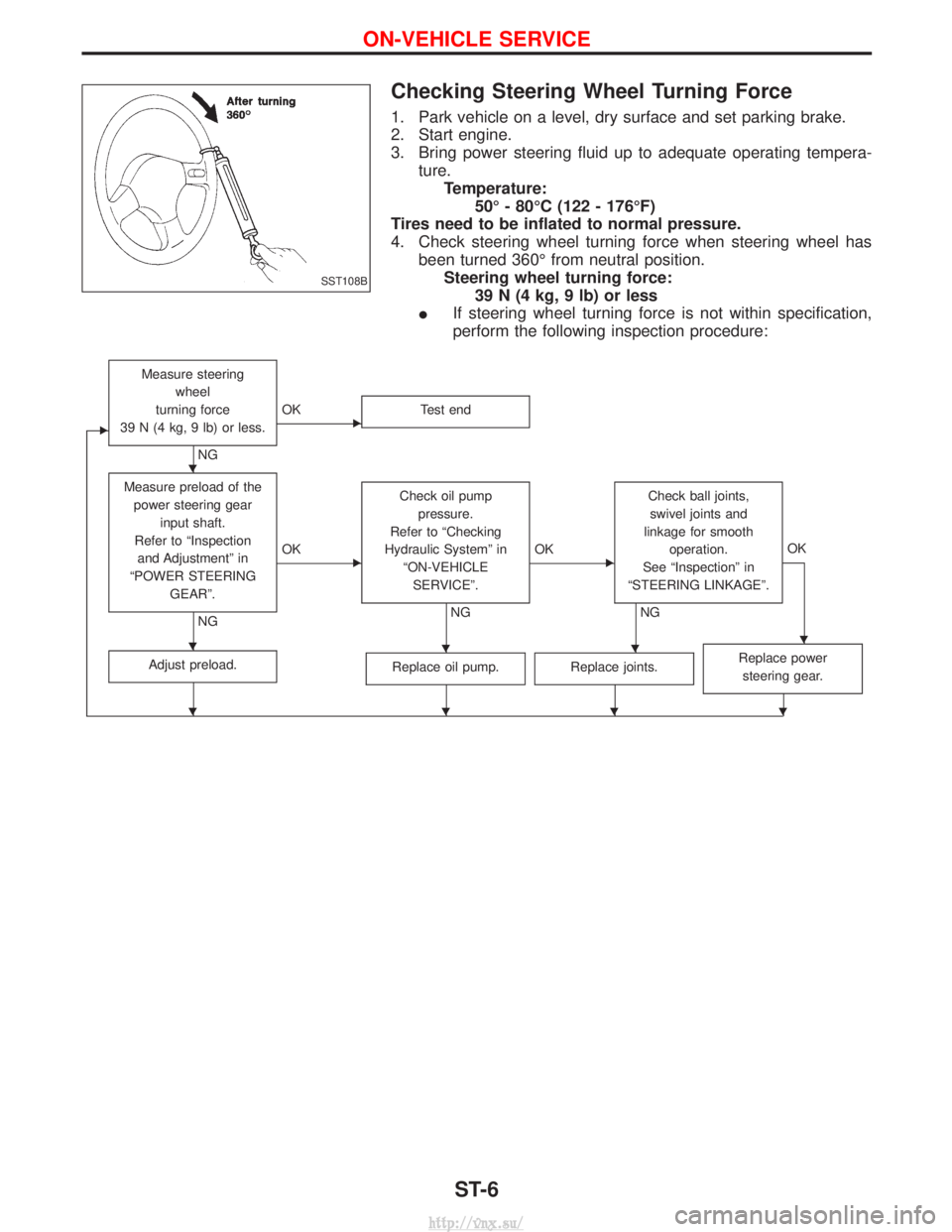
I If steering wheel turning force is not within specification,
perform the following inspection procedure:
E
Measure steering
wheel
turning force
39 N (4 kg, 9 lb) or less.
NG
EOK Test end
Measure preload of the
power steering gear input shaft.
Refer to ªInspection and Adjustmentº in
ªPOWER STEERING GEARº.
NG
EOK Check oil pump
pressure.
Refer to ªChecking
Hydraulic Systemº in ªON-VEHICLESERVICEº.
NG
EOK Check ball joints,
swivel joints and
linkage for smooth operation.
See ªInspectionº in
ªSTEERING LINKAGEº.
NG OK
Adjust preload.Replace oil pump.Replace joints.Replace power
steering gear.
SST108B
H
HHHH
HHHH
ON-VEHICLE SERVICE
ST-6
http://vnx.su/
Page 1275 of 1833
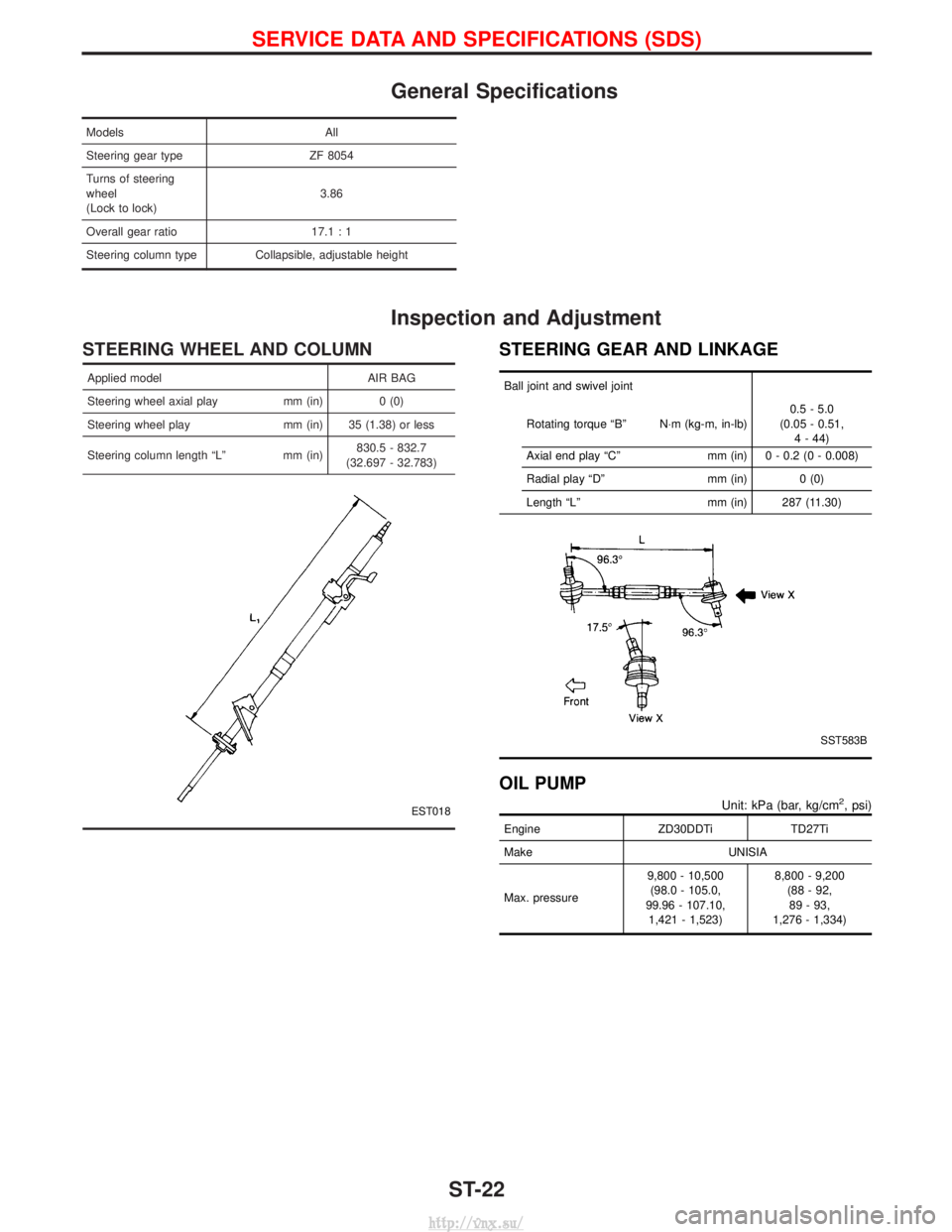
General Specifications
ModelsAll
Steering gear type ZF 8054
Turns of steering
wheel
(Lock to lock) 3.86
Overall gear ratio 17.1 : 1
Steering column type Collapsible, adjustable height
Inspection and Adjustment
STEERING WHEEL AND COLUMN
Applied model AIR BAG
Steering wheel axial play mm (in) 0 (0)
Steering wheel play mm (in) 35 (1.38) or less
Steering column length ªLº mm (in) 830.5 - 832.7
(32.697 - 32.783)
EST018
STEERING GEAR AND LINKAGE
Ball joint and swivel joint
Rotating torque ªBº N×m (kg-m, in-lb) 0.5 - 5.0
(0.05 - 0.51, 4 - 44)
Axial end play ªCº mm (in) 0 - 0.2 (0 - 0.008)
Radial play ªDº mm (in) 0 (0)
Length ªLº mm (in) 287 (11.30)
SST583B
OIL PUMP
Unit: kPa (bar, kg/cm2, psi)
EngineZD30DDTiTD27Ti
Make UNISIA
Max. pressure 9,800 - 10,500
(98.0 - 105.0,
99.96 - 107.10, 1,421 - 1,523) 8,800 - 9,200
(88 - 92,89 - 93,
1,276 - 1,334)
SERVICE DATA AND SPECIFICATIONS (SDS)
ST-22
http://vnx.su/