brakes NISSAN TERRANO 2004 Service Repair Manual
[x] Cancel search | Manufacturer: NISSAN, Model Year: 2004, Model line: TERRANO, Model: NISSAN TERRANO 2004Pages: 1833, PDF Size: 53.42 MB
Page 52 of 1833
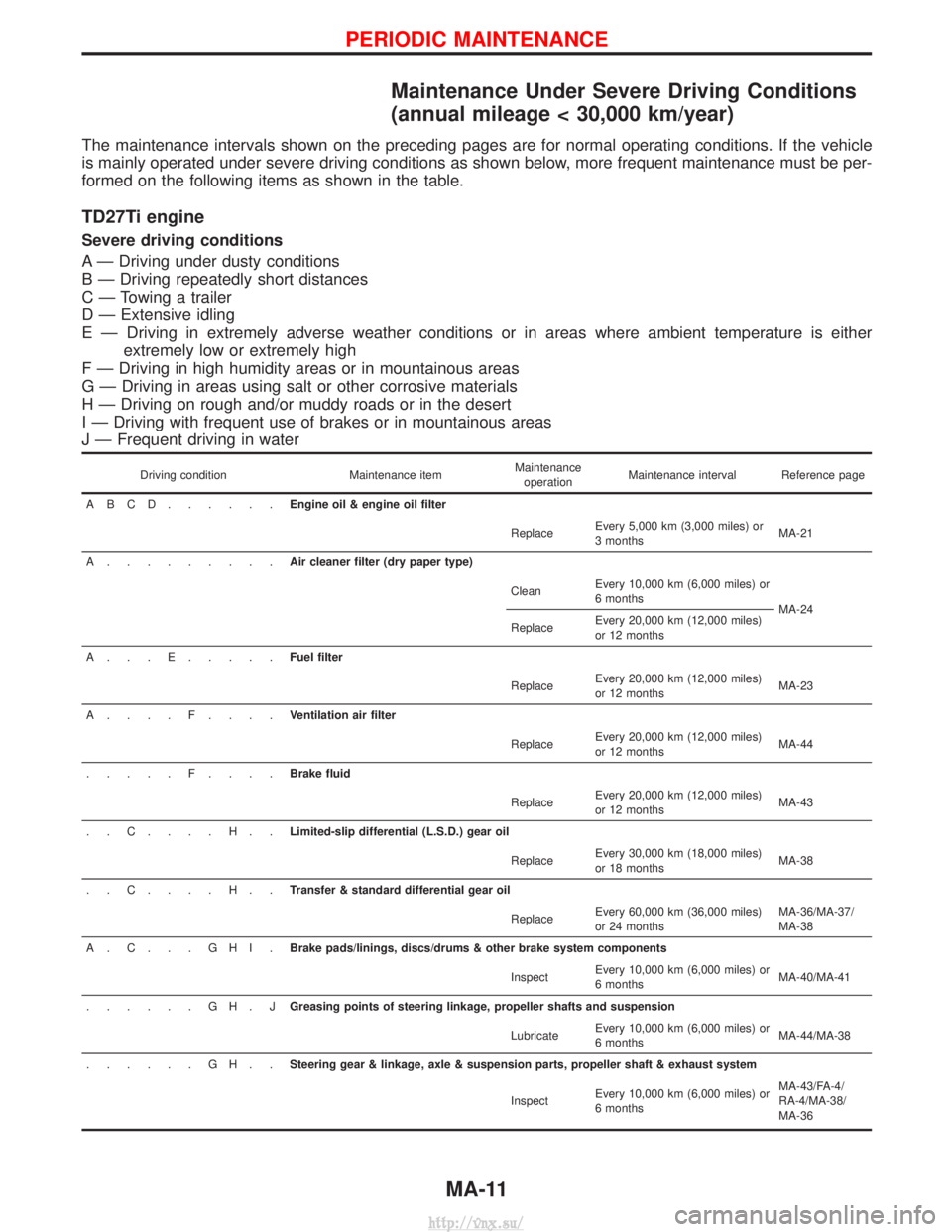
Maintenance Under Severe Driving Conditions
(annual mileage < 30,000 km/year)
The maintenance intervals shown on the preceding pages are for normal operating conditions. If the vehicle
is mainly operated under severe driving conditions as shown below, more frequent maintenance must be per-
formed on the following items as shown in the table.
TD27Ti engine
Severe driving conditions
A Ð Driving under dusty conditions
B Ð Driving repeatedly short distances
C Ð Towing a trailer
D Ð Extensive idling
E Ð Driving in extremely adverse weather conditions or in areas where ambient temperature is eitherextremely low or extremely high
F Ð Driving in high humidity areas or in mountainous areas
G Ð Driving in areas using salt or other corrosive materials
H Ð Driving on rough and/or muddy roads or in the desert
I Ð Driving with frequent use of brakes or in mountainous areas
J Ð Frequent driving in water
Driving condition Maintenance itemMaintenance
operation Maintenance interval Reference page
ABCD......Engine oil & engine oil filter ReplaceEvery 5,000 km (3,000 miles) or
3 months MA-21
A.........Air cleaner filter (dry paper type) CleanEvery 10,000 km (6,000 miles) or
6 months
MA-24
Replace Every 20,000 km (12,000 miles)
or 12 months
A...E.....Fuel filter
ReplaceEvery 20,000 km (12,000 miles)
or 12 months MA-23
A....F....Ventilation air filter ReplaceEvery 20,000 km (12,000 miles)
or 12 months MA-44
.....F....Brake fluid ReplaceEvery 20,000 km (12,000 miles)
or 12 months MA-43
..C....H..Limited-slip differential (L.S.D.) gear oil ReplaceEvery 30,000 km (18,000 miles)
or 18 months MA-38
..C....H..Transfer & standard differential gear oil ReplaceEvery 60,000 km (36,000 miles)
or 24 months MA-36/MA-37/
MA-38
A.C...GHI.Brake pads/linings, discs/drums & other brake system components
InspectEvery 10,000 km (6,000 miles) or
6 months MA-40/MA-41
......GH.J Greasing points of steering linkage, propeller shafts and suspension
LubricateEvery 10,000 km (6,000 miles) or
6 months MA-44/MA-38
......GH..Steering gear & linkage, axle & suspension parts, propeller shaft & exhaust system
InspectEvery 10,000 km (6,000 miles) or
6 months MA-43/FA-4/
RA-4/MA-38/
MA-36
PERIODIC MAINTENANCE
MA-11
http://vnx.su/
Page 55 of 1833
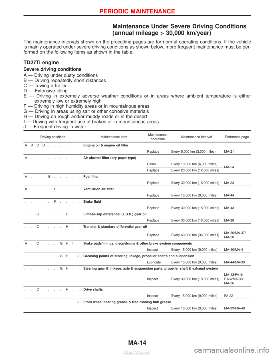
Maintenance Under Severe Driving Conditions
(annual mileage > 30,000 km/year)
The maintenance intervals shown on the preceding pages are for normal operating conditions. If the vehicle
is mainly operated under severe driving conditions as shown below, more frequent maintenance must be per-
formed on the following items as shown in the table.
TD27Ti engine
Severe driving conditions
A Ð Driving under dusty conditions
B Ð Driving repeatedly short distances
C Ð Towing a trailer
D Ð Extensive idling
E Ð Driving in extremely adverse weather conditions or in areas where ambient temperature is eitherextremely low or extremely high
F Ð Driving in high humidity areas or in mountainous areas
G Ð Driving in areas using salt or other corrosive materials
H Ð Driving on rough and/or muddy roads or in the desert
I Ð Driving with frequent use of brakes or in mountainous areas
J Ð Frequent driving in water
Driving condition Maintenance itemMaintenance
operation Maintenance interval Reference page
ABCD......Engine oil & engine oil filter Replace Every 5,000 km (3,000 miles) MA-21
A.........Air cleaner filter (dry paper type) Clean Every 10,000 km (6,000 miles)MA-24
Replace Every 20,000 km (12,000 miles)
A...E.....Fuel filter Replace Every 30,000 km (18,000 miles) MA-23
A....F....Ventilation air filter Replace Every 15,000 km (9,000 miles) MA-44
.....F....Brake fluid Replace Every 30,000 km (18,000 miles) MA-43
..C....H..Limited-slip differential (L.S.D.) gear oil Replace Every 30,000 km (18,000 miles) MA-38
..C....H..Transfer & standard differential gear oil
Replace Every 60,000 km (36,000 miles)MA-36/MA-37/
MA-38
A.C...GHI.Brake pads/linings, discs/drums & other brake system components Inspect Every 15,000 km (9,000 miles) MA-40/MA-41
......GH.J Greasing points of steering linkage, propeller shafts and suspension
Lubricate Every 15,000 km (9,000 miles) MA-44/MA-38
......GH..Steering gear & linkage, axle & suspension parts, propeller shaft & exhaust system
Inspect Every 30,000 km (18,000 miles)MA-43/FA-4/
RA-4/MA-38/
MA-36
..C....H..Drive shafts Inspect Every 15,000 km (9,000 miles) FA-22
.........J Front wheel bearing grease & free running hub grease
Inspect Every 15,000 km (9,000 miles) MA-39/MA-40
PERIODIC MAINTENANCE
MA-14
http://vnx.su/
Page 837 of 1833
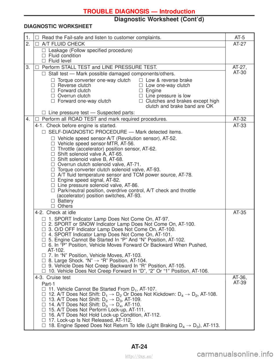
DIAGNOSTIC WORKSHEET
1.lRead the Fail-safe and listen to customer complaints. AT-5
2. lA/T FLUID CHECK AT-27
l Leakage (Follow specified procedure)
l Fluid condition
l Fluid level
3. lPerform STALL TEST and LINE PRESSURE TEST. AT-27,
AT-30
l Stall test Ð Mark possible damaged components/others.
l Torque converter one-way clutch
l Reverse clutch
l Forward clutch
l Overrun clutch
l Forward one-way clutch l
Low & reverse brake
l Low one-way clutch
l Engine
l Line pressure is low
l Clutches and brakes except high
clutch and brake band are OK
l Line pressure test Ð Suspected parts:
4. lPerform all ROAD TEST and mark required procedures. AT-32
4-1. Check before engine is started. AT-33 l SELF-DIAGNOSTIC PROCEDURE Ð Mark detected items.
l Vehicle speed sensor×A/T (Revolution sensor), AT-52.
l Vehicle speed sensor×MTR, AT-56.
l Throttle (accelerator) position sensor, AT-62.
l Shift solenoid valve A, AT-65.
l Shift solenoid valve B, AT-68.
l Overrun clutch solenoid valve, AT-71.
l Torque converter clutch solenoid valve, AT-93.
l A/T fluid temperature sensor and TCM power source, AT-78.
l Engine speed signal, AT-82.
l Line pressure solenoid valve, AT-86.
l Park/neutral position, overdrive control, A/T check and throttle
(accelerator) position switches, AT-93.
l Battery
l Others
4-2. Check at idle AT-35 l 1. SPORT Indicator Lamp Does Not Come On, AT-97.
l 2. SPORT or SNOW Indicator Lamp Does Not Come On, AT-100.
l 3. O/D OFF Indicator Lamp Does Not Come On, AT-100.
l 4. SPORT Indicator Lamp Does Not Come On, AT-101.
l 5. Engine Cannot Be Started In ªPº And ªNº Position, AT-102.
l 6. In ªPº Position, Vehicle Moves Forward Or Backward When Pushed,
AT-102.
l 7. In ªNº Position, Vehicle Moves, AT-103.
l 8. Large Shock. ªNº ,ªRº Position, AT-104.
l 9. Vehicle Does Not Creep Backward In ªRº Position, AT-105.
l 10. Vehicle Does Not Creep Forward In ªDº, ª2º Or ª1º Position, AT-106.
4-3. Cruise test AT-36,
AT-39
Part-1
l 11. Vehicle Cannot Be Started From D
1, AT-107.
l 12. A/T Does Not Shift: D
1,D2Or Does Not Kickdown: D4,D2, AT-108.
l 13. A/T Does Not Shift: D
2,D3, AT-109.
l 14. A/T Does Not Shift: D
3,D4, AT-110.
l 15. A/T Does Not Perform Lock-up, AT-111.
l 16. A/T Does Not Hold Lock-up Condition, AT-112.
l 17. Lock-up Is Not Released, AT-112.
l 18. Engine Speed Does Not Return To Idle (Light Braking D
4,D3), AT-113.
TROUBLE DIAGNOSIS Ð Introduction
Diagnostic Worksheet (Cont'd)
AT-24
http://vnx.su/
Page 856 of 1833
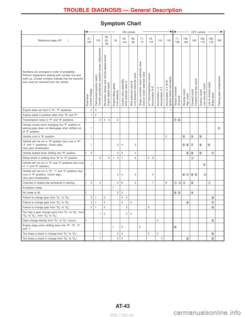
Symptom Chart
FON vehicleEFOFF vehicleE
Reference page (AT- )27,
120 11 9 56,
62,
82 30
65,
144 68,
86 71,
74 78,
11 8 11 8 11 8 71,
128 156,
160 162162,
170 166,
176 180
Numbers are arranged in order of probability.
Perform inspections starting with number one and
work up. Circled numbers indicate that the transmis-
sion must be removed from the vehicle.
Fluid level
Control linkage
Park/neutral position switch
Throttle (accelerator) position sensor (Adjustment)
Revolution sensor and vehicle speed sensor
Engine speed signal
Engine idling speed
Line pressure
Control valve assembly
Shift solenoid valve A
Shift solenoid valve B
Line pressure solenoid valve
Torque converter clutch solenoid valve
Overrun clutch solenoid valve
A/T fluid temperature sensor
Accumulator N-D
Accumulator 1-2
Accumulator 2-3
Accumulator 3-4 (N-R)
Ignition switch and starter
Torque converter
Oil pump
Reverse clutch
High clutch
Forward clutch
Forward one-way clutch
Overrun clutch
Low one-way clutch
Low & reverse brake
Brake band
Parking pawl components
Engine does not start in ªNº, ªPº positions. . 2 3................1. ......... .
Engine starts in position other than ªNº and ªPº. . 1 2 ................. . ......... .
Transmission noise in ªPº and ªNº positions. 1 . . 3 4 5 . 2 ............q
7q6........ .
Vehicle moves when changing into ªPº position or
parking gear does not disengage when shifted out
of ªPº position. . 1.................. .
.........q
2
Vehicle runs in ªNº position.
. 1................2. .. q4.q3.q5... .
Vehicle will not run in ªRº position (but runs in ªDº,
ª2º and ª1º positions). Clutch slips.
Very poor acceleration. . 1.....24..3........ ..
q
5q6q7.q8.q9..
Vehicle braked when shifting into ªRº position. 1 2 .....35..4........ ... q
6q8.q9.. q7.
Sharp shock in shifting from ªNº to ªDº position. . . . 2 . 5137 . . 6 . . 48.... ....q
10..... .
Vehicle will not run in ªDº and ª2º positions (but runs
in ª1º and ªRº position). . 1.................. .
......q
2.. .
Vehicle will not run in ªDº, ª1º and ª2º positions (but
runs in ªRº position). Clutch slips.
Very poor acceleration. 1 ......24..3...5.... ..
q
6q7q8q9.q10.. .
Clutches or brakes slip somewhat in starting. 1 2 . 3 . . . 4 6 . . 5 . . . 7 . . 8 . q
13q12q10.q9... q11..
Excessive creep. . .....1............. . ......... .
No creep at all. 1 ......23........... q
6q5..q4..... .
Failure to change gear from ªD
1ºtoªD2º. . 21.5...43.......... . ........q6.
Failure to change gear from ªD
2ºtoªD3º. . 21.5...4.3......... ... q6.....q7.
Failure to change gear from ªD
3ºtoªD4º. . 21.4....3....5..... . ........q6.
Too high a gear change point from ªD
1ºtoªD2º, from
ªD2ºtoªD3º, from ªD3ºtoªD4º. . ..12....34......... .
......... .
Gear change directly from ªD
1ºtoªD3º occurs. 1 ...............2... . ........q3.
Engine stops when shifting lever into ªRº, ªDº, ª2º
and ª1º. . .....1.3...2.......
q
4......... .
Too sharp a shock in change from ªD
1ºtoªD2º. . ..1...24.....5.3... . ........q6.
Too sharp a shock in change from ªD
2ºtoªD3º. . ..1...24........3.. ... q5.....q6.
TROUBLE DIAGNOSIS Ð General Description
AT-43
http://vnx.su/
Page 1016 of 1833
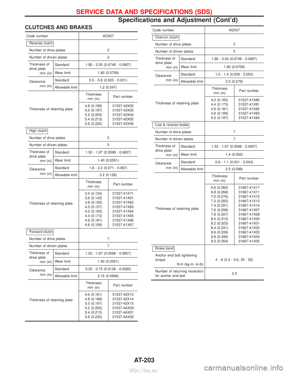
CLUTCHES AND BRAKES
Code number4GX07
Reverse clutch
Number of drive plates 2
Number of driven plates 2
Thickness of
drive plate mm (in) Standard 1.90 - 2.05 (0.0748 - 0.0807)
Wear limit 1.80 (0.0709)
Clearance mm (in) Standard 0.5 - 0.8 (0.020 - 0.031)
Allowable limit 1.2 (0.047)
Thickness of retaining plate Thickness
mm (in) Part number
4.8 (0.189)
5.0 (0.197)
5.2 (0.205)
5.4 (0.213)
5.6 (0.220) 31537-42X02
31537-42X03
31537-42X04
31537-42X05
31537-42X06
High clutch
Number of drive plates 5
Number of driven plates 5
Thickness of
drive plate mm (in) Standard 1.52 - 1.67 (0.0598 - 0.0657)
Wear limit 1.40 (0.0551)
Clearance mm (in) Standard 1.8 - 2.2 (0.071 - 0.087)
Allowable limit 3.2 (0.126)
Thickness of retaining plate Thickness
mm (in) Part number
3.4 (0.134)
3.6 (0.142)
3.8 (0.150)
4.0 (0.157)
4.2 (0.165)
4.4 (0.173)
4.6 (0.181)
4.8 (0.189) 31537-41X71
31537-41X61
31537-41X62
31537-41X63
31537-41X64
31537-41X65
31537-41X66
31537-41X67
Forward clutch
Number of drive plates 7
Number of driven plates 7
Thickness of
drive plate mm (in) Standard 1.52 - 1.67 (0.0598 - 0.0657)
Wear limit 1.40 (0.0551)
Clearance mm (in) Standard 0.35 - 0.75 (0.0138 - 0.0295)
Allowable limit 2.15 (0.0846)
Thickness of retaining plate Thickness
mm (in) Part number
4.6 (0.181)
4.8 (0.189)
5.0 (0.197)
5.2 (0.205)
5.4 (0.213)
5.6 (0.220) 31537-42X13
31537-42X14
31537-42X15
31537-4AX00
31537-4AX01
31537-4AX02
Code number 4GX07
Overrun clutch
Number of drive plates 3
Number of driven plates 5
Thickness of
drive plate mm (in) Standard 1.90 - 2.05 (0.0748 - 0.0807)
Wear limit 1.80 (0.0709)
Clearance mm (in) Standard 1.0 - 1.4 (0.039 - 0.055)
Allowable limit 2.0 (0.079)
Thickness of retaining plate Thickness
mm (in) Part number
4.2 (0.165)
4.4 (0.173)
4.6 (0.181)
4.8 (0.189)
5.0 (0.197) 31537-41X80
31537-41X81
31537-41X82
31537-41X83
31537-41X84
Low & reverse brake
Number of drive plates 7
Number of driven plates 7
Thickness of
drive plate mm (in) Standard 1.52 - 1.67 (0.0598 - 0.0657)
Wear limit 1.4 (0.055)
Clearance mm (in) Standard 0.8 - 1.1 (0.031 - 0.043)
Allowable limit 2.5 (0.098)
Thickness of retaining plate Thickness
mm (in) Part number
6.6 (0.260)
6.8 (0.268)
7.0 (0.276)
7.2 (0.283)
7.4 (0.291)
7.6 (0.299)
7.8 (0.307)
8.0 (0.315)
8.2 (0.323)
8.4 (0.331)
8.6 (0.339)
8.8 (0.346)
9.0 (0.354) 31667-41X17
31667-41X11
31667-41X12
31667-41X13
31667-41X14
31667-41X07
31667-41X08
31667-41X00
31667-41X01
31667-41X02
31667-41X03
31667-41X04
31667-41X05
Brake band
Anchor end bolt tightening
torque N×m (kg-m, in-lb) 4 - 6 (0.4 - 0.6, 35 - 52)
Number of returning revolution
for anchor end bolt 2.5
SERVICE DATA AND SPECIFICATIONS (SDS)
Specifications and Adjustment (Cont'd)
AT-203
http://vnx.su/
Page 1170 of 1833
Supplement Restraint System (SRS) ªAIR BAGº
and ªSEAT BELT PRE-TENSIONERº
The Supplemental Restraint System ªAir Bagº and ªSeat Belt Pre-tensionerº, used along with a seat belt, help
to reduce the risk or severity or injury to the driver and front passenger in a collision. The Supplemental
Restraint System consists of an air bag module (located in the center of the steering wheel and on the instru-
ment panel on the passenger side, where fitted), seat belt pre-tensioners, a diagnosis sensor unit, warning
lamp, wiring harness and spiral cable. Information necessary to service the system safely is included in the
BT sectionof this Service Manual.
WARNING:
I To avoid rendering the SRS inoperative (which could increase the risk of personal injury or death
in the event of a collision which would result in air bag inflation), all maintenance must be per-
formed by an authorized NISSAN dealer.
I Improper maintenance, including incorrect removal and installation of the SRS, can lead to per-
sonal injury caused by unintentional activation of the system.
I Do not use electrical test equipment on any circuit related to the SRS unless instructed to in this
Service Manual. SRS wiring harnesses (except ªSEAT BELT-TENSIONERº connector) can be iden-
tified with yellow harness connector and with yellow harness protector or yellow insulation tape
before the harness connectors.
Precautions
IUse only ªDOT 4º fluid from a sealed container.
I Never reuse drained brake fluid.
I Be careful not to splash brake fluid on painted areas; it
may cause paint damage. If brake fluid is splashed on
painted areas, wash it away with water immediately.
I To clean master cylinder parts, disc brake caliper parts or
wheel cylinder parts, use clean brake fluid.
I Never use mineral oils such as Petrol or kerosene. They
will ruin rubber parts of hydraulic system.
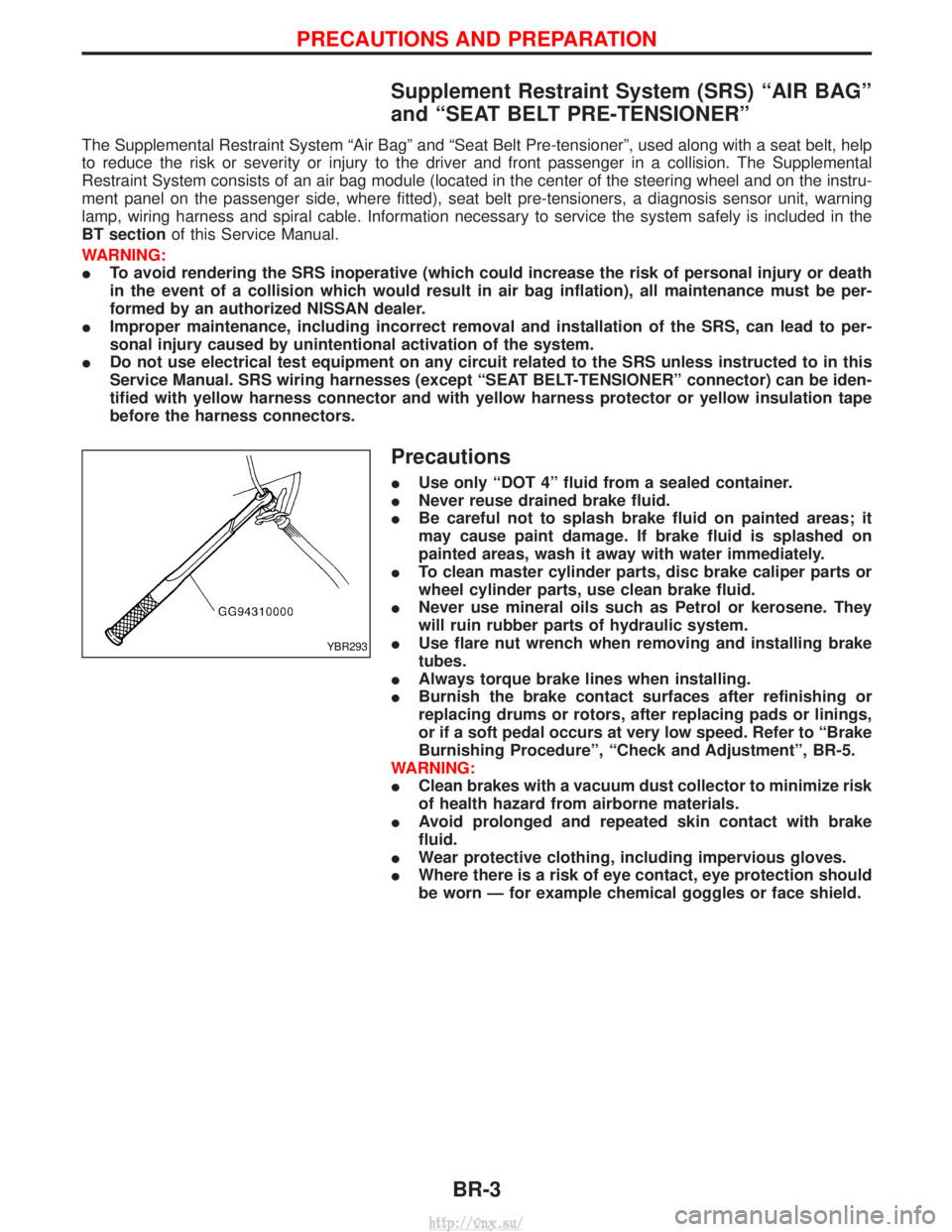
I Use flare nut wrench when removing and installing brake
tubes.
I Always torque brake lines when installing.
I Burnish the brake contact surfaces after refinishing or
replacing drums or rotors, after replacing pads or linings,
or if a soft pedal occurs at very low speed. Refer to ªBrake
Burnishing Procedureº, ªCheck and Adjustmentº, BR-5.
WARNING:
I Clean brakes with a vacuum dust collector to minimize risk
of health hazard from airborne materials.
I Avoid prolonged and repeated skin contact with brake
fluid.
I Wear protective clothing, including impervious gloves.
I Where there is a risk of eye contact, eye protection should
be worn Ð for example chemical goggles or face shield.
YBR293
PRECAUTIONS AND PREPARATION
BR-3
http://vnx.su/
Page 1205 of 1833
Purpose
The Anti-lock Brake System (ABS) with an integrated Electronic Brake force Distribution (EBD) system con-
sists of electronic and hydraulic components. It allows you to control the braking force so that wheel lock can
be avoided during braking.
The advantages of ABS with EBD
1) Better tracking performance through improved steering wheel control.
2) Improved maneuverability and safer vehicle control.
3) Improved vehicle stability by preventing flat spins.
4) Shorter stopping distance and optimal utilisation of the rear brakes under many different circumstances.
Operation
IABS with EBD has self-test capabilities. The ABS warning lamp is illuminated for 1 second each time the
ignition switch is turned ªONº. After the engine is started, the ABS warning lamp turns off. An ABS self-test
is performed the first time the vehicle reaches 6 km/h (4 MPH) to ensure the system is operational. A
mechanical noise may be heard as the ABS performs this self-test and is a normal part of the self-test
feature. If a malfunction is detected during this check, the ABS warning lamp will stay on.
During the self-test, it also performs a EBD check when it detects a failure the ABS warning light will go
on simultaneously with the brake warning light and an audible sound will sound constantly.
I EBD system will only operate when the ABS is not in active status and it uses the inlet valves of ABS con-
trol unit to limit the pressure to the rear wheels when they tend to go into slip.
I When the vehicle speed is less than 10 km/h (6 MPH) the ABS system does not operate.
I While driving, a mechanical noise may be heard during ABS operation, this is a normal system condition.
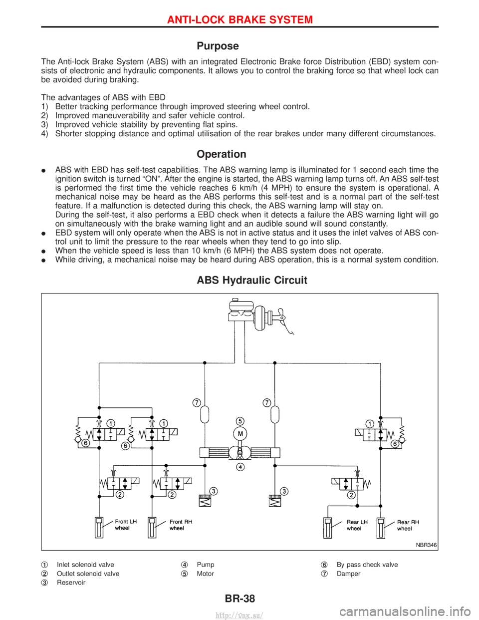
ABS Hydraulic Circuit
q1Inlet solenoid valve
q
2Outlet solenoid valve
q
3Reservoir q
4Pump
q
5Motor q
6By pass check valve
q
7Damper
NBR346
ANTI-LOCK BRAKE SYSTEM
BR-38
http://vnx.su/