tire pressure NISSAN TERRANO 2004 Service Repair Manual
[x] Cancel search | Manufacturer: NISSAN, Model Year: 2004, Model line: TERRANO, Model: NISSAN TERRANO 2004Pages: 1833, PDF Size: 53.42 MB
Page 44 of 1833
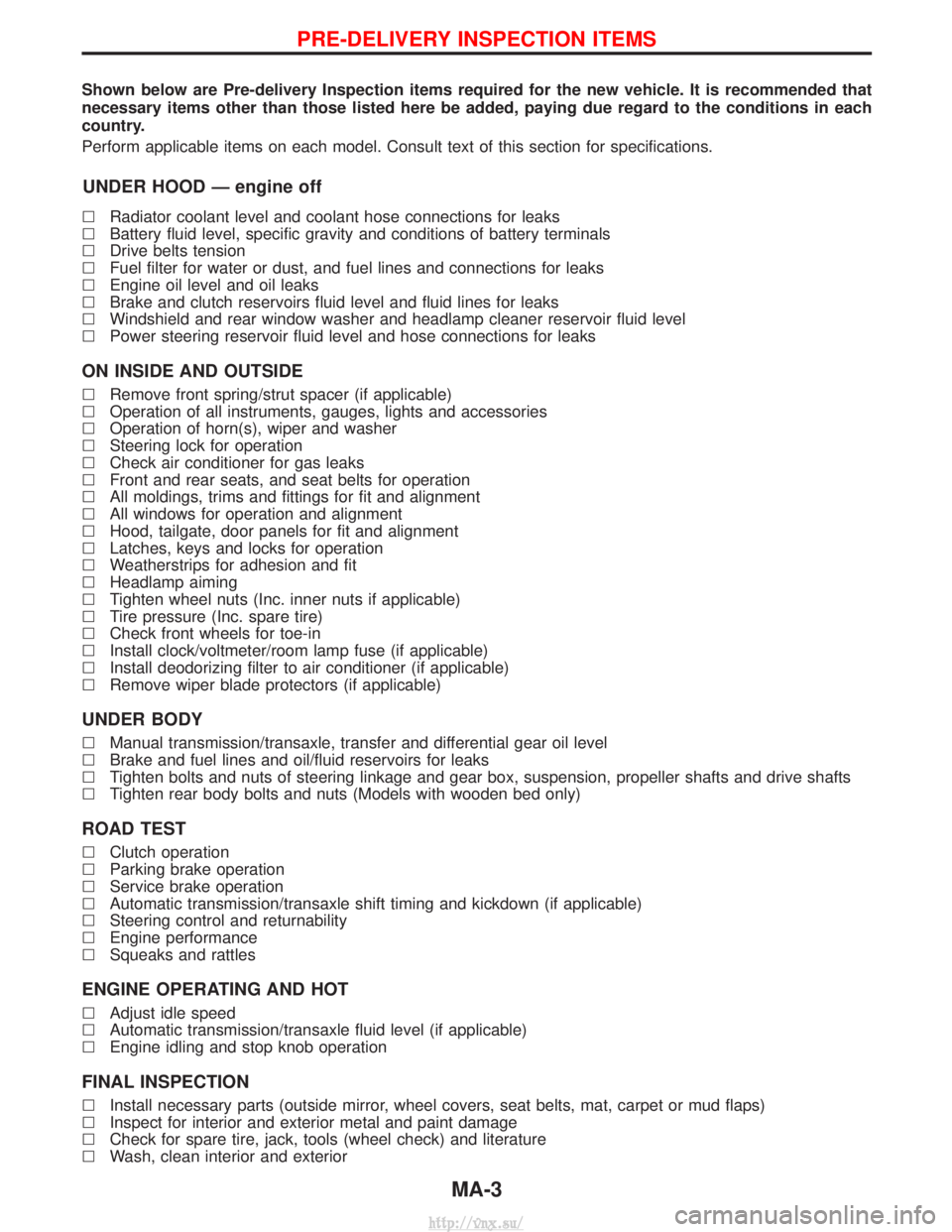
Shown below are Pre-delivery Inspection items required for the new vehicle. It is recommended that
necessary items other than those listed here be added, paying due regard to the conditions in each
country.
Perform applicable items on each model. Consult text of this section for specifications.
UNDER HOOD Ð engine off
lRadiator coolant level and coolant hose connections for leaks
l Battery fluid level, specific gravity and conditions of battery terminals
l Drive belts tension
l Fuel filter for water or dust, and fuel lines and connections for leaks
l Engine oil level and oil leaks
l Brake and clutch reservoirs fluid level and fluid lines for leaks
l Windshield and rear window washer and headlamp cleaner reservoir fluid level
l Power steering reservoir fluid level and hose connections for leaks
ON INSIDE AND OUTSIDE
lRemove front spring/strut spacer (if applicable)
l Operation of all instruments, gauges, lights and accessories
l Operation of horn(s), wiper and washer
l Steering lock for operation
l Check air conditioner for gas leaks
l Front and rear seats, and seat belts for operation
l All moldings, trims and fittings for fit and alignment
l All windows for operation and alignment
l Hood, tailgate, door panels for fit and alignment
l Latches, keys and locks for operation
l Weatherstrips for adhesion and fit
l Headlamp aiming
l Tighten wheel nuts (Inc. inner nuts if applicable)
l Tire pressure (Inc. spare tire)
l Check front wheels for toe-in
l Install clock/voltmeter/room lamp fuse (if applicable)
l Install deodorizing filter to air conditioner (if applicable)
l Remove wiper blade protectors (if applicable)
UNDER BODY
lManual transmission/transaxle, transfer and differential gear oil level
l Brake and fuel lines and oil/fluid reservoirs for leaks
l Tighten bolts and nuts of steering linkage and gear box, suspension, propeller shafts and drive shafts
l Tighten rear body bolts and nuts (Models with wooden bed only)
ROAD TEST
lClutch operation
l Parking brake operation
l Service brake operation
l Automatic transmission/transaxle shift timing and kickdown (if applicable)
l Steering control and returnability
l Engine performance
l Squeaks and rattles
ENGINE OPERATING AND HOT
lAdjust idle speed
l Automatic transmission/transaxle fluid level (if applicable)
l Engine idling and stop knob operation
FINAL INSPECTION
lInstall necessary parts (outside mirror, wheel covers, seat belts, mat, carpet or mud flaps)
l Inspect for interior and exterior metal and paint damage
l Check for spare tire, jack, tools (wheel check) and literature
l Wash, clean interior and exterior
PRE-DELIVERY INSPECTION ITEMS
MA-3
http://vnx.su/
Page 45 of 1833
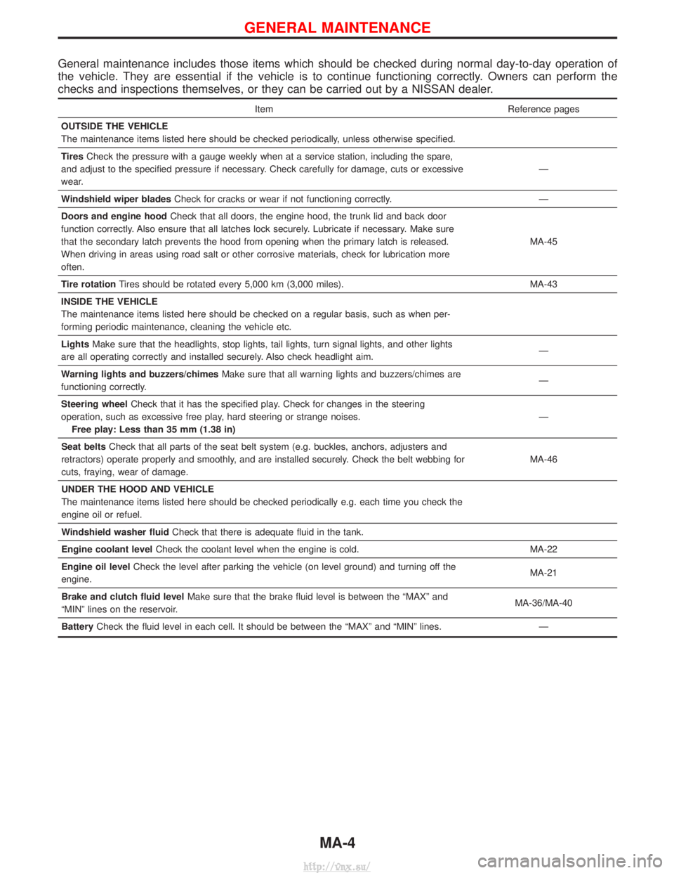
General maintenance includes those items which should be checked during normal day-to-day operation of
the vehicle. They are essential if the vehicle is to continue functioning correctly. Owners can perform the
checks and inspections themselves, or they can be carried out by a NISSAN dealer.
ItemReference pages
OUTSIDE THE VEHICLE
The maintenance items listed here should be checked periodically, unless otherwise specified.
Tires Check the pressure with a gauge weekly when at a service station, including the spare,
and adjust to the specified pressure if necessary. Check carefully for damage, cuts or excessive
wear. Ð
Windshield wiper blades Check for cracks or wear if not functioning correctly. Ð
Doors and engine hood Check that all doors, the engine hood, the trunk lid and back door
function correctly. Also ensure that all latches lock securely. Lubricate if necessary. Make sure
that the secondary latch prevents the hood from opening when the primary latch is released.
When driving in areas using road salt or other corrosive materials, check for lubrication more
often. MA-45
Tire rotation Tires should be rotated every 5,000 km (3,000 miles). MA-43
INSIDE THE VEHICLE
The maintenance items listed here should be checked on a regular basis, such as when per-
forming periodic maintenance, cleaning the vehicle etc.
Lights Make sure that the headlights, stop lights, tail lights, turn signal lights, and other lights
are all operating correctly and installed securely. Also check headlight aim. Ð
Warning lights and buzzers/chimes Make sure that all warning lights and buzzers/chimes are
functioning correctly. Ð
Steering wheel Check that it has the specified play. Check for changes in the steering
operation, such as excessive free play, hard steering or strange noises. Free play: Less than 35 mm (1.38 in) Ð
Seat belts Check that all parts of the seat belt system (e.g. buckles, anchors, adjusters and
retractors) operate properly and smoothly, and are installed securely. Check the belt webbing for
cuts, fraying, wear of damage. MA-46
UNDER THE HOOD AND VEHICLE
The maintenance items listed here should be checked periodically e.g. each time you check the
engine oil or refuel.
Windshield washer fluid Check that there is adequate fluid in the tank.
Engine coolant level Check the coolant level when the engine is cold. MA-22
Engine oil level Check the level after parking the vehicle (on level ground) and turning off the
engine. MA-21
Brake and clutch fluid level Make sure that the brake fluid level is between the ªMAXº and
ªMINº lines on the reservoir. MA-36/MA-40
Battery Check the fluid level in each cell. It should be between the ªMAXº and ªMINº lines. Ð
GENERAL MAINTENANCE
MA-4
http://vnx.su/
Page 1180 of 1833
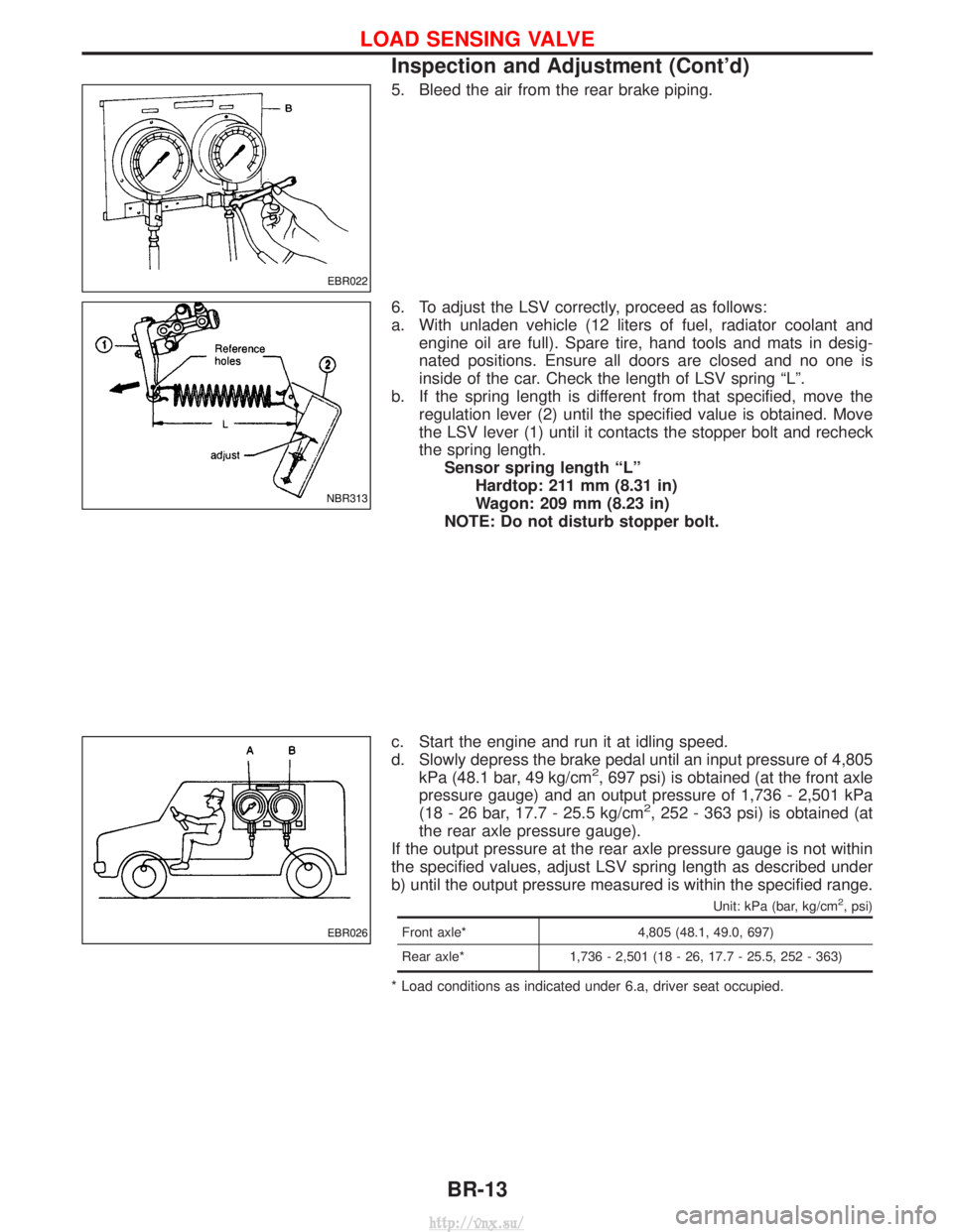
5. Bleed the air from the rear brake piping.
6. To adjust the LSV correctly, proceed as follows:
a. With unladen vehicle (12 liters of fuel, radiator coolant andengine oil are full). Spare tire, hand tools and mats in desig-
nated positions. Ensure all doors are closed and no one is
inside of the car. Check the length of LSV spring ªLº.
b. If the spring length is different from that specified, move the regulation lever (2) until the specified value is obtained. Move
the LSV lever (1) until it contacts the stopper bolt and recheck
the spring length.Sensor spring length ªLº Hardtop: 211 mm (8.31 in)
Wagon: 209 mm (8.23 in)
NOTE: Do not disturb stopper bolt.
c. Start the engine and run it at idling speed.
d. Slowly depress the brake pedal until an input pressure of 4,805 kPa (48.1 bar, 49 kg/cm
2, 697 psi) is obtained (at the front axle
pressure gauge) and an output pressure of 1,736 - 2,501 kPa
(18 - 26 bar, 17.7 - 25.5 kg/cm
2, 252 - 363 psi) is obtained (at
the rear axle pressure gauge).
If the output pressure at the rear axle pressure gauge is not within
the specified values, adjust LSV spring length as described under
b) until the output pressure measured is within the specified range.
Unit: kPa (bar, kg/cm2, psi)
Front axle* 4,805 (48.1, 49.0, 697)
Rear axle* 1,736 - 2,501 (18 - 26, 17.7 - 25.5, 252 - 363)
* Load conditions as indicated under 6.a, driver seat occupied.
EBR022
NBR313
EBR026
LOAD SENSING VALVE
Inspection and Adjustment (Cont'd)
BR-13
http://vnx.su/
Page 1242 of 1833
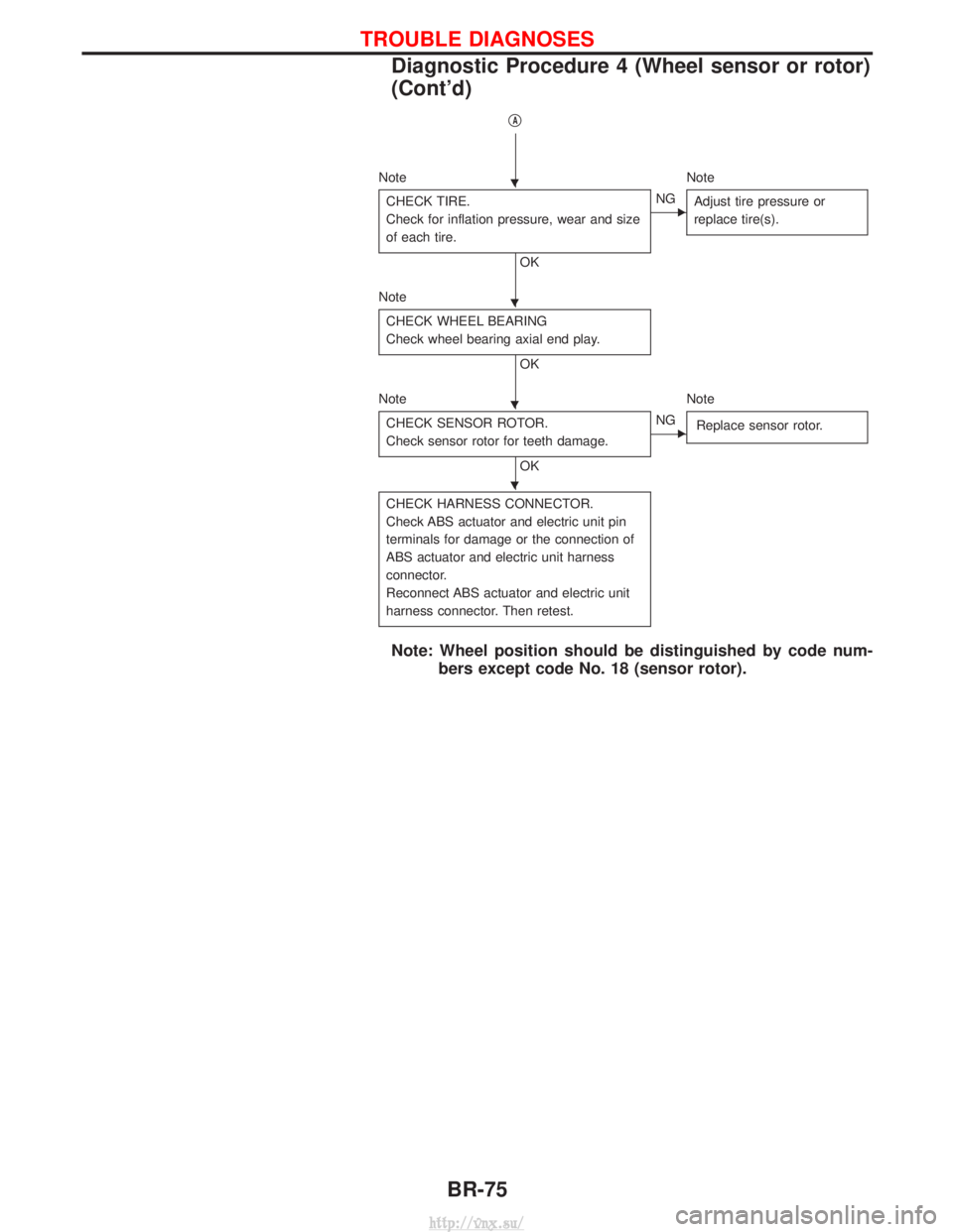
qA
NoteNote
CHECK TIRE.
Check for inflation pressure, wear and size
of each tire.
OK
ENG Adjust tire pressure or
replace tire(s).
Note
CHECK WHEEL BEARING
Check wheel bearing axial end play.
OK
Note Note CHECK SENSOR ROTOR.
Check sensor rotor for teeth damage.
OK
ENG Replace sensor rotor.
CHECK HARNESS CONNECTOR.
Check ABS actuator and electric unit pin
terminals for damage or the connection of
ABS actuator and electric unit harness
connector.
Reconnect ABS actuator and electric unit
harness connector. Then retest.
Note: Wheel position should be distinguished by code num-
bers except code No. 18 (sensor rotor).
H
H
H
H
TROUBLE DIAGNOSES
Diagnostic Procedure 4 (Wheel sensor or rotor)
(Cont'd)
BR-75
http://vnx.su/
Page 1259 of 1833
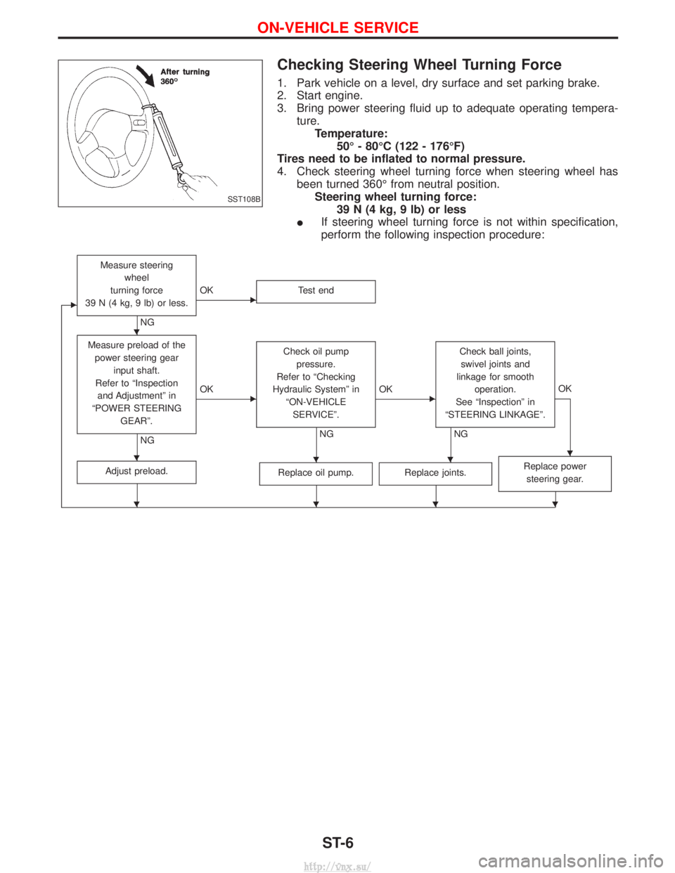
Checking Steering Wheel Turning Force
1. Park vehicle on a level, dry surface and set parking brake.
2. Start engine.
3. Bring power steering fluid up to adequate operating tempera-ture.Temperature: 50É - 80ÉC (122 - 176ÉF)
Tires need to be inflated to normal pressure.
4. Check steering wheel turning force when steering wheel has been turned 360É from neutral position.Steering wheel turning force: 39 N (4 kg, 9 lb) or less
I If steering wheel turning force is not within specification,
perform the following inspection procedure:
E
Measure steering
wheel
turning force
39 N (4 kg, 9 lb) or less.
NG
EOK Test end
Measure preload of the
power steering gear input shaft.
Refer to ªInspection and Adjustmentº in
ªPOWER STEERING GEARº.
NG
EOK Check oil pump
pressure.
Refer to ªChecking
Hydraulic Systemº in ªON-VEHICLESERVICEº.
NG
EOK Check ball joints,
swivel joints and
linkage for smooth operation.
See ªInspectionº in
ªSTEERING LINKAGEº.
NG OK
Adjust preload.Replace oil pump.Replace joints.Replace power
steering gear.
SST108B
H
HHHH
HHHH
ON-VEHICLE SERVICE
ST-6
http://vnx.su/
Page 1260 of 1833
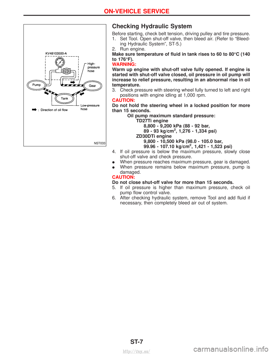
Checking Hydraulic System
Before starting, check belt tension, driving pulley and tire pressure.
1. Set Tool. Open shut-off valve, then bleed air. (Refer to ªBleed-ing Hydraulic Systemº, ST-5.)
2. Run engine.
Make sure temperature of fluid in tank rises to 60 to 80ÉC (140
to 176ÉF).
WARNING:
Warm up engine with shut-off valve fully opened. If engine is
started with shut-off valve closed, oil pressure in oil pump will
increase to relief pressure, resulting in an abnormal rise in oil
temperature.
3. Check pressure with steering wheel fully turned to left and right positions with engine idling at 1,000 rpm.
CAUTION:
Do not hold the steering wheel in a locked position for more
than 15 seconds. Oil pump maximum standard pressure:TD27Ti engine8,800 - 9,200 kPa (88 - 92 bar,
89 - 93 kg/cm
2, 1,276 - 1,334 psi)
ZD30DTi engine 9,800 - 10,500 kPa (98.0 - 105.0 bar,
99.96 - 107.10 kg/cm
2, 1,421 - 1,523 psi)
4. If oil pressure is below the maximum pressure, slowly close shut-off valve and check pressure.
I When pressure reaches maximum pressure, gear is damaged.
I When pressure remains below maximum pressure, pump is
damaged.
CAUTION:
Do not close shut-off valve for more than 15 seconds.
5. If oil pressure is higher than maximum pressure, check oil pump flow control valve.
6. After checking hydraulic system, remove Tool and add fluid if necessary, then completely bleed air out of system.NST033
ON-VEHICLE SERVICE
ST-7
http://vnx.su/
Page 1540 of 1833
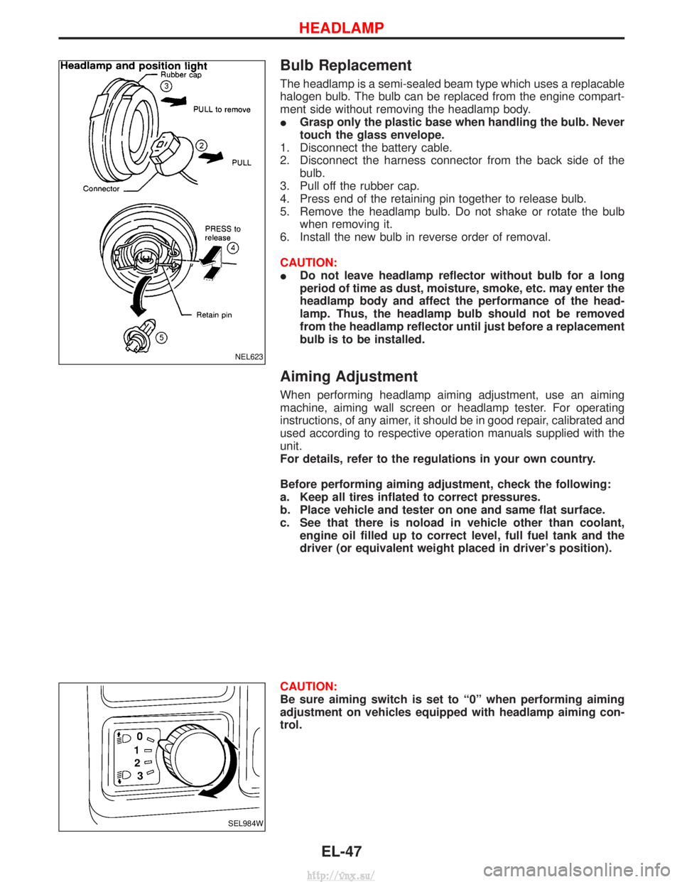
Bulb Replacement
The headlamp is a semi-sealed beam type which uses a replacable
halogen bulb. The bulb can be replaced from the engine compart-
ment side without removing the headlamp body.
IGrasp only the plastic base when handling the bulb. Never
touch the glass envelope.
1. Disconnect the battery cable.
2. Disconnect the harness connector from the back side of the bulb.
3. Pull off the rubber cap.
4. Press end of the retaining pin together to release bulb.
5. Remove the headlamp bulb. Do not shake or rotate the bulb when removing it.
6. Install the new bulb in reverse order of removal.
CAUTION:
I Do not leave headlamp reflector without bulb for a long
period of time as dust, moisture, smoke, etc. may enter the
headlamp body and affect the performance of the head-
lamp. Thus, the headlamp bulb should not be removed
from the headlamp reflector until just before a replacement
bulb is to be installed.
Aiming Adjustment
When performing headlamp aiming adjustment, use an aiming
machine, aiming wall screen or headlamp tester. For operating
instructions, of any aimer, it should be in good repair, calibrated and
used according to respective operation manuals supplied with the
unit.
For details, refer to the regulations in your own country.
Before performing aiming adjustment, check the following:
a. Keep all tires inflated to correct pressures.
b. Place vehicle and tester on one and same flat surface.
c. See that there is noload in vehicle other than coolant,
engine oil filled up to correct level, full fuel tank and the
driver (or equivalent weight placed in driver's position).
CAUTION:
Be sure aiming switch is set to ª0º when performing aiming
adjustment on vehicles equipped with headlamp aiming con-
trol.
NEL623
SEL984W
HEADLAMP
EL-47
http://vnx.su/
Page 1550 of 1833
Front Fog Lamp Aiming Adjustment
When performing fog lamp aiming adjustment, use an aiming
machine, aiming wall screen or headlamp tester. The aimer should
be in good operational condition, calibrated and used according to
the relevant operation manuals supplied with the unit.
If an aimer is not available, aiming adjustment can be done as fol-
lows:
For details, refer to the regulations in your own country.
CAUTION:
IKeep all tires inflated to correct pressures.
I Place vehicle and tester on one and the same flat surface.
I Ensure that there is no-load in the vehicle other than
coolant, engine oil (filled up to correct level), full fuel tank
and the driver (or equivalent weight placed in driver's posi-
tion).
For details of front fog lamp aiming adjustment, refer to ªAiming
Adjustmentº, EL-47.
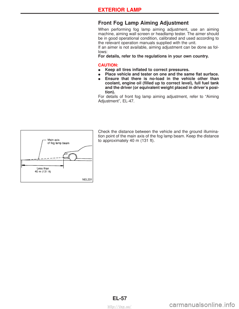
Check the distance between the vehicle and the ground illumina-
tion point of the main axis of the fog lamp beam. Keep the distance
to approximately 40 m (131 ft).
NEL331
EXTERIOR LAMP
EL-57
http://vnx.su/