washer fluid NISSAN TERRANO 2004 Service Repair Manual
[x] Cancel search | Manufacturer: NISSAN, Model Year: 2004, Model line: TERRANO, Model: NISSAN TERRANO 2004Pages: 1833, PDF Size: 53.42 MB
Page 44 of 1833
Shown below are Pre-delivery Inspection items required for the new vehicle. It is recommended that
necessary items other than those listed here be added, paying due regard to the conditions in each
country.
Perform applicable items on each model. Consult text of this section for specifications.
UNDER HOOD Ð engine off
lRadiator coolant level and coolant hose connections for leaks
l Battery fluid level, specific gravity and conditions of battery terminals
l Drive belts tension
l Fuel filter for water or dust, and fuel lines and connections for leaks
l Engine oil level and oil leaks
l Brake and clutch reservoirs fluid level and fluid lines for leaks
l Windshield and rear window washer and headlamp cleaner reservoir fluid level
l Power steering reservoir fluid level and hose connections for leaks
ON INSIDE AND OUTSIDE
lRemove front spring/strut spacer (if applicable)
l Operation of all instruments, gauges, lights and accessories
l Operation of horn(s), wiper and washer
l Steering lock for operation
l Check air conditioner for gas leaks
l Front and rear seats, and seat belts for operation
l All moldings, trims and fittings for fit and alignment
l All windows for operation and alignment
l Hood, tailgate, door panels for fit and alignment
l Latches, keys and locks for operation
l Weatherstrips for adhesion and fit
l Headlamp aiming
l Tighten wheel nuts (Inc. inner nuts if applicable)
l Tire pressure (Inc. spare tire)
l Check front wheels for toe-in
l Install clock/voltmeter/room lamp fuse (if applicable)
l Install deodorizing filter to air conditioner (if applicable)
l Remove wiper blade protectors (if applicable)
UNDER BODY
lManual transmission/transaxle, transfer and differential gear oil level
l Brake and fuel lines and oil/fluid reservoirs for leaks
l Tighten bolts and nuts of steering linkage and gear box, suspension, propeller shafts and drive shafts
l Tighten rear body bolts and nuts (Models with wooden bed only)
ROAD TEST
lClutch operation
l Parking brake operation
l Service brake operation
l Automatic transmission/transaxle shift timing and kickdown (if applicable)
l Steering control and returnability
l Engine performance
l Squeaks and rattles
ENGINE OPERATING AND HOT
lAdjust idle speed
l Automatic transmission/transaxle fluid level (if applicable)
l Engine idling and stop knob operation
FINAL INSPECTION
lInstall necessary parts (outside mirror, wheel covers, seat belts, mat, carpet or mud flaps)
l Inspect for interior and exterior metal and paint damage
l Check for spare tire, jack, tools (wheel check) and literature
l Wash, clean interior and exterior
PRE-DELIVERY INSPECTION ITEMS
MA-3
http://vnx.su/
Page 45 of 1833
General maintenance includes those items which should be checked during normal day-to-day operation of
the vehicle. They are essential if the vehicle is to continue functioning correctly. Owners can perform the
checks and inspections themselves, or they can be carried out by a NISSAN dealer.
ItemReference pages
OUTSIDE THE VEHICLE
The maintenance items listed here should be checked periodically, unless otherwise specified.
Tires Check the pressure with a gauge weekly when at a service station, including the spare,
and adjust to the specified pressure if necessary. Check carefully for damage, cuts or excessive
wear. Ð
Windshield wiper blades Check for cracks or wear if not functioning correctly. Ð
Doors and engine hood Check that all doors, the engine hood, the trunk lid and back door
function correctly. Also ensure that all latches lock securely. Lubricate if necessary. Make sure
that the secondary latch prevents the hood from opening when the primary latch is released.
When driving in areas using road salt or other corrosive materials, check for lubrication more
often. MA-45
Tire rotation Tires should be rotated every 5,000 km (3,000 miles). MA-43
INSIDE THE VEHICLE
The maintenance items listed here should be checked on a regular basis, such as when per-
forming periodic maintenance, cleaning the vehicle etc.
Lights Make sure that the headlights, stop lights, tail lights, turn signal lights, and other lights
are all operating correctly and installed securely. Also check headlight aim. Ð
Warning lights and buzzers/chimes Make sure that all warning lights and buzzers/chimes are
functioning correctly. Ð
Steering wheel Check that it has the specified play. Check for changes in the steering
operation, such as excessive free play, hard steering or strange noises. Free play: Less than 35 mm (1.38 in) Ð
Seat belts Check that all parts of the seat belt system (e.g. buckles, anchors, adjusters and
retractors) operate properly and smoothly, and are installed securely. Check the belt webbing for
cuts, fraying, wear of damage. MA-46
UNDER THE HOOD AND VEHICLE
The maintenance items listed here should be checked periodically e.g. each time you check the
engine oil or refuel.
Windshield washer fluid Check that there is adequate fluid in the tank.
Engine coolant level Check the coolant level when the engine is cold. MA-22
Engine oil level Check the level after parking the vehicle (on level ground) and turning off the
engine. MA-21
Brake and clutch fluid level Make sure that the brake fluid level is between the ªMAXº and
ªMINº lines on the reservoir. MA-36/MA-40
Battery Check the fluid level in each cell. It should be between the ªMAXº and ªMINº lines. Ð
GENERAL MAINTENANCE
MA-4
http://vnx.su/
Page 62 of 1833
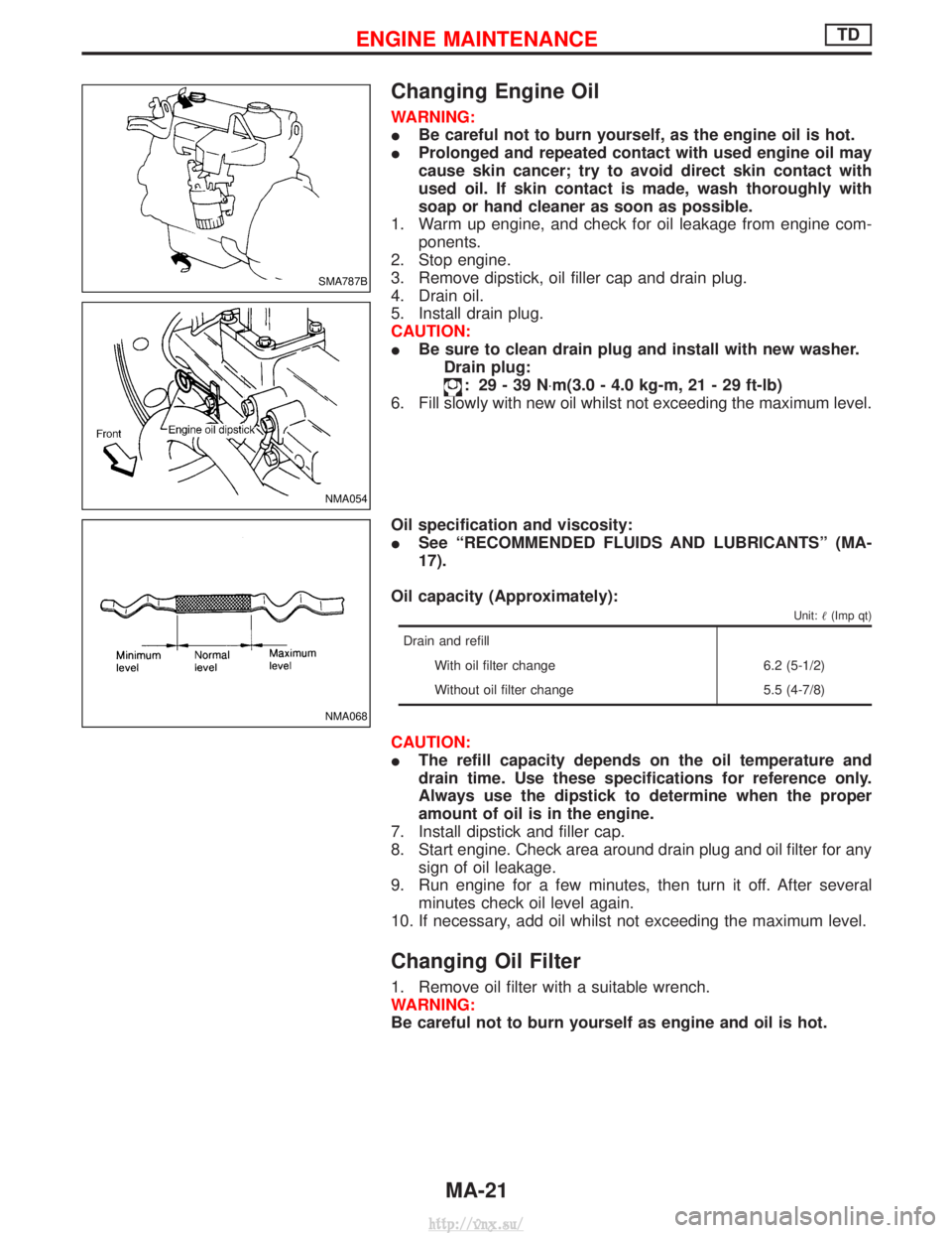
Changing Engine Oil
WARNING:
IBe careful not to burn yourself, as the engine oil is hot.
I Prolonged and repeated contact with used engine oil may
cause skin cancer; try to avoid direct skin contact with
used oil. If skin contact is made, wash thoroughly with
soap or hand cleaner as soon as possible.
1. Warm up engine, and check for oil leakage from engine com- ponents.
2. Stop engine.
3. Remove dipstick, oil filler cap and drain plug.
4. Drain oil.
5. Install drain plug.
CAUTION:
I Be sure to clean drain plug and install with new washer.
Drain plug:
: 29-39N ×m(3.0 - 4.0 kg-m, 21 - 29 ft-lb)
6. Fill slowly with new oil whilst not exceeding the maximum level.
Oil specification and viscosity:
I See ªRECOMMENDED FLUIDS AND LUBRICANTSº (MA-
17).
Oil capacity (Approximately):
Unit: (Imp qt)
Drain and refill
With oil filter change 6.2 (5-1/2)
Without oil filter change 5.5 (4-7/8)
CAUTION:
IThe refill capacity depends on the oil temperature and
drain time. Use these specifications for reference only.
Always use the dipstick to determine when the proper
amount of oil is in the engine.
7. Install dipstick and filler cap.
8. Start engine. Check area around drain plug and oil filter for any sign of oil leakage.
9. Run engine for a few minutes, then turn it off. After several minutes check oil level again.
10. If necessary, add oil whilst not exceeding the maximum level.
Changing Oil Filter
1. Remove oil filter with a suitable wrench.
WARNING:
Be careful not to burn yourself as engine and oil is hot.
SMA787B
NMA054
NMA068
ENGINE MAINTENANCETD
MA-21
http://vnx.su/
Page 71 of 1833
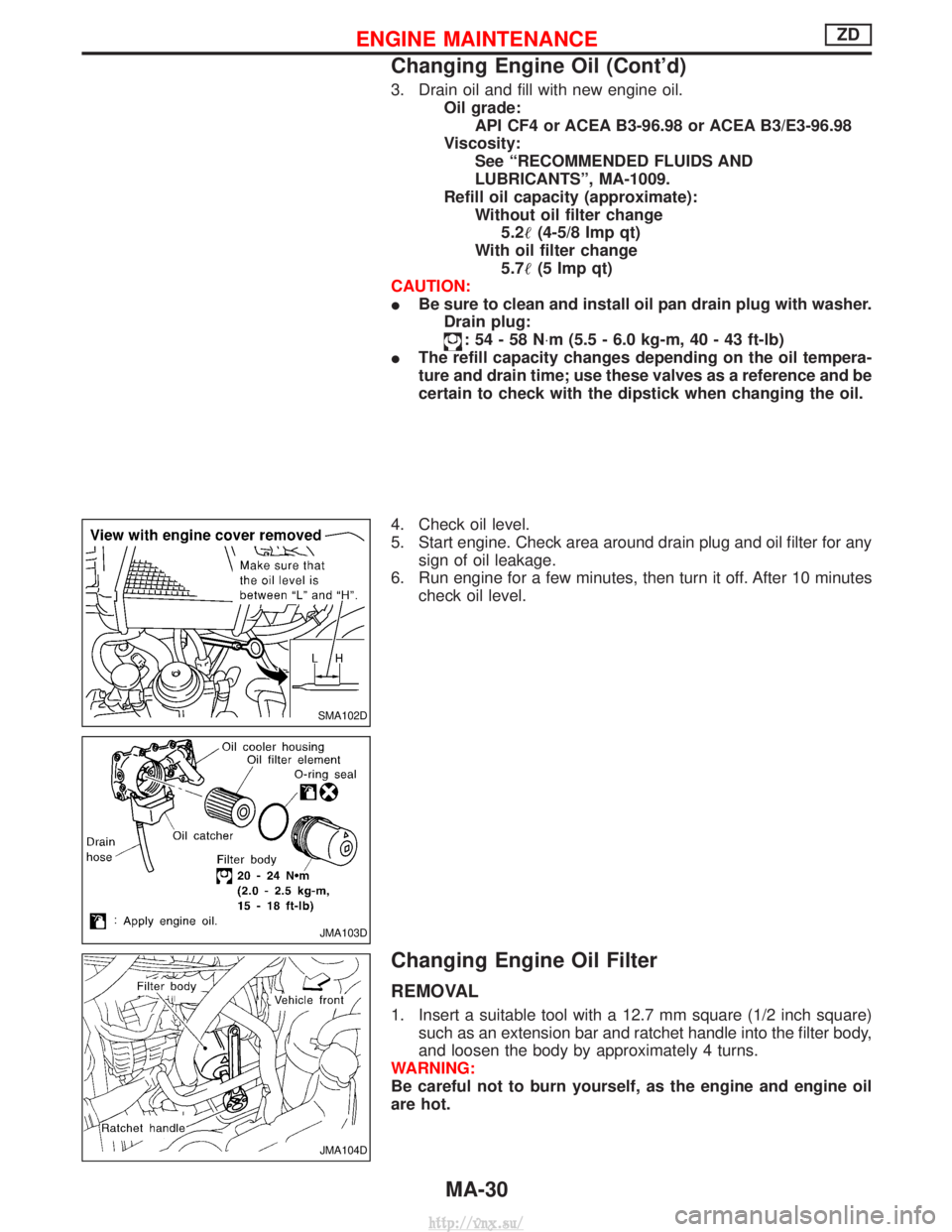
3. Drain oil and fill with new engine oil.Oil grade:API CF4 or ACEA B3-96.98 or ACEA B3/E3-96.98
Viscosity: See ªRECOMMENDED FLUIDS AND
LUBRICANTSº, MA-1009.
Refill oil capacity (approximate): Without oil filter change5.2 (4-5/8 Imp qt)
With oil filter change 5.7 (5 Imp qt)
CAUTION:
I Be sure to clean and install oil pan drain plug with washer.
Drain plug:
:54-58N ×m (5.5 - 6.0 kg-m, 40 - 43 ft-lb)
I The refill capacity changes depending on the oil tempera-
ture and drain time; use these valves as a reference and be
certain to check with the dipstick when changing the oil.
4. Check oil level.
5. Start engine. Check area around drain plug and oil filter for any sign of oil leakage.
6. Run engine for a few minutes, then turn it off. After 10 minutes check oil level.
Changing Engine Oil Filter
REMOVAL
1. Insert a suitable tool with a 12.7 mm square (1/2 inch square)such as an extension bar and ratchet handle into the filter body,
and loosen the body by approximately 4 turns.
WARNING:
Be careful not to burn yourself, as the engine and engine oil
are hot.
SMA102D
JMA103D
JMA104D
ENGINE MAINTENANCEZD
Changing Engine Oil (Cont'd)
MA-30
http://vnx.su/
Page 815 of 1833
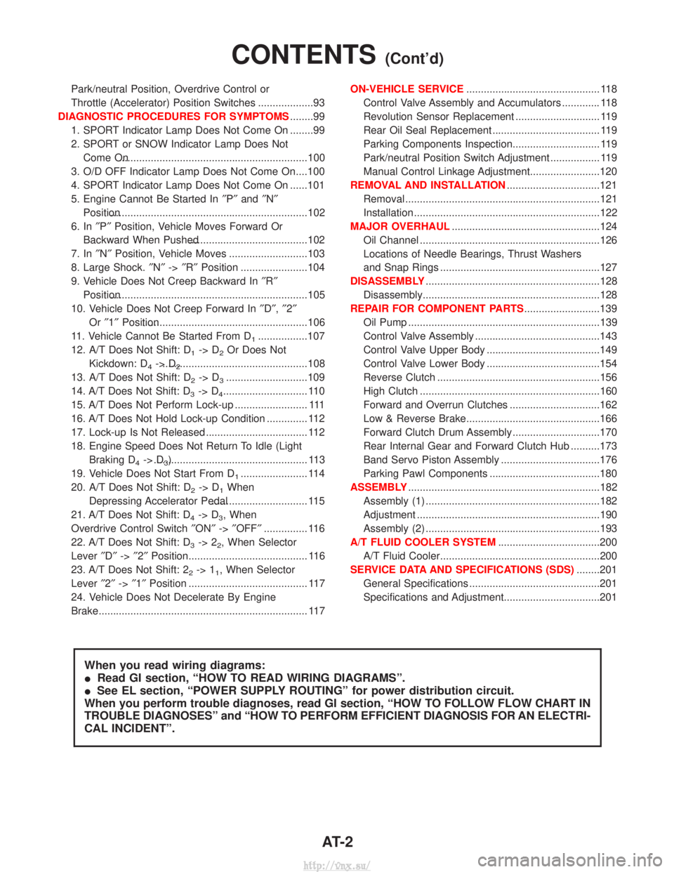
Park/neutral Position, Overdrive Control or
Throttle (Accelerator) Position Switches ...................93
DIAGNOSTIC PROCEDURES FOR SYMPTOMS ........99
1. SPORT Indicator Lamp Does Not Come On ........99
2. SPORT or SNOW Indicator Lamp Does Not Come On.................................................................100
3. O/D OFF Indicator Lamp Does Not Come On....100
4. SPORT Indicator Lamp Does Not Come On ......101
5. Engine Cannot Be Started In ²P² and ²N²
Position....................................................................102
6. In ²P² Position, Vehicle Moves Forward Or
Backward When Pushed.........................................102
7. In ²N² Position, Vehicle Moves ...........................103
8. Large Shock. ²N² ->²R² Position .......................104
9. Vehicle Does Not Creep Backward In ²R²
Position....................................................................105
10. Vehicle Does Not Creep Forward In ²D² ,²2²
Or ²1² Position.........................................................106
11. Vehicle Cannot Be Started From D
1.................107
12. A/T Does Not Shift: D
1-> D2Or Does Not
Kickdown: D
4-> D2..................................................108
13. A/T Does Not Shift: D
2-> D3............................109
14. A/T Does Not Shift: D
3-> D4............................. 110
15. A/T Does Not Perform Lock-up ......................... 111
16. A/T Does Not Hold Lock-up Condition .............. 112
17. Lock-up Is Not Released ................................... 112
18. Engine Speed Does Not Return To Idle (Light Braking D
4-> D3)..................................................... 113
19. Vehicle Does Not Start From D
1....................... 114
20. A/T Does Not Shift: D
2-> D1When
Depressing Accelerator Pedal................................. 115
21. A/T Does Not Shift: D
4-> D3, When
Overdrive Control Switch ²ON² ->²OFF² ............... 116
22. A/T Does Not Shift: D
3-> 22, When Selector
Lever ²D² ->²2² Position......................................... 116
23. A/T Does Not Shift: 2
2-> 11, When Selector
Lever ²2² ->²1² Position ......................................... 117
24. Vehicle Does Not Decelerate By Engine
Brake........................................................................\
117 ON-VEHICLE SERVICE
.............................................. 118
Control Valve Assembly and Accumulators ............. 118
Revolution Sensor Replacement ............................. 119
Rear Oil Seal Replacement ..................................... 119
Parking Components Inspection.............................. 119
Park/neutral Position Switch Adjustment ................. 119
Manual Control Linkage Adjustment........................120
REMOVAL AND INSTALLATION ................................121
Removal ...................................................................121
Installation ................................................................122
MAJOR OVERHAUL ...................................................124
Oil Channel ..............................................................126
Locations of Needle Bearings, Thrust Washers
and Snap Rings .......................................................127
DISASSEMBLY ............................................................128
Disassembly.............................................................128
REPAIR FOR COMPONENT PARTS ..........................139
Oil Pump ..................................................................139
Control Valve Assembly ...........................................143
Control Valve Upper Body .......................................149
Control Valve Lower Body .......................................154
Reverse Clutch ........................................................156
High Clutch ..............................................................160
Forward and Overrun Clutches ...............................162
Low & Reverse Brake..............................................166
Forward Clutch Drum Assembly ..............................170
Rear Internal Gear and Forward Clutch Hub ..........173
Band Servo Piston Assembly ..................................176
Parking Pawl Components ......................................180
ASSEMBLY ..................................................................182
Assembly (1) ............................................................182
Adjustment ...............................................................190
Assembly (2) ............................................................193
A/T FLUID COOLER SYSTEM ...................................200
A/T Fluid Cooler.......................................................200
SERVICE DATA AND SPECIFICATIONS (SDS) ........201
General Specifications .............................................201
Specifications and Adjustment.................................201
When you read wiring diagrams:
I Read GI section, ªHOW TO READ WIRING DIAGRAMSº.
I See EL section, ªPOWER SUPPLY ROUTINGº for power distribution circuit.
When you perform trouble diagnoses, read GI section, ªHOW TO FOLLOW FLOW CHART IN
TROUBLE DIAGNOSESº and ªHOW TO PERFORM EFFICIENT DIAGNOSIS FOR AN ELECTRI-
CAL INCIDENTº.
CONTENTS(Cont'd)
AT- 2
http://vnx.su/
Page 818 of 1833
IBefore assembly, apply a coat of recommended ATF to all parts. Apply petroleum jelly to protect O-rings
and seals, and to hold bearings and washers in place during assembly. Do not use grease.
I Extreme care should be taken to avoid damage to O-rings, seals and gaskets when assembling.
I After overhaul, refill the transmission with new ATF.
I When the A/T drain plug is removed, only some of the fluid is drained. Old A/T fluid will remain in torque
converter and ATF cooling system.
Always follow the procedures under ªChanging A/T Fluidº in the MA section when changing A/T fluid.
Service Notice or Precautions
FAIL-SAFE
The TCM has an electronic Fail-Safe (limp home mode). This allows the vehicle to be driven even if a major
electrical input/output device circuit is damaged.
Under Fail-Safe, the vehicle always runs in third gear even with a shift lever position of ª1º, ª2º or ªDº. Cus-
tomer may complain of ªsluggish or poor accelerationº.
When the Fail-Safe operation occurs the next time the key is turned to the ªONº position, the SPORT indica-
tor lamp will blink for about 8 seconds. (For diagnosis, refer to AT-33.)
Fail-Safe may activate without electrical circuit damages if the vehicle is driven under extreme conditions (such
as excessive wheel spins and emergency braking immediately afterwards). In this case, turn the ignition key
ªOFFº for 5 seconds and then ªONº to recover normal shift pattern.
The blinking of the SPORT indicator lamp for about 8 seconds will appear only once and be cleared. The cus-
tomer may resume normal driving conditions by chance.
Always follow the ªWORK FLOWº (Refer to AT-26).
The SELF-DIAGNOSIS results will be as follows:
The first SELF-DIAGNOSIS will indicate the damage of the vehicle speed sensor or the revolution sensor.
During the next SELF-DIAGNOSIS performed after checking the sensor, no damages will be indicated.
PREPARATION AND PRECAUTIONS
Precautions (Cont'd)
AT- 5
http://vnx.su/
Page 1258 of 1833
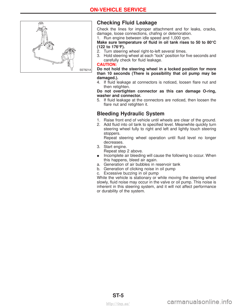
Checking Fluid Leakage
Check the lines for improper attachment and for leaks, cracks,
damage, loose connections, chafing or deterioration.
1. Run engine between idle speed and 1,000 rpm.
Make sure temperature of fluid in oil tank rises to 50 to 80ÉC
(122 to 176ÉF).
2. Turn steering wheel right-to-left several times.
3. Hold steering wheel at each ªlockº position for five seconds andcarefully check for fluid leakage.
CAUTION:
Do not hold the steering wheel in a locked position for more
than 10 seconds (There is possibility that oil pump may be
damaged.).
4. If fluid leakage at connectors is noticed, loosen flare nut and then retighten.
Do not overtighten connector as this can damage O-ring,
washer and connector.
5. If fluid leakage at the connectors are noticed, then loosen the flare nut and retighten it.
Bleeding Hydraulic System
1. Raise front end of vehicle until wheels are clear of the ground.
2. Add fluid into oil tank to specified level. Meanwhile quickly turnsteering wheel fully to right and left and lightly touch steering
stoppers.
Repeat steering wheel operation until fluid level no longer
decreases.
3. Start engine. Repeat step 2 above.
I Incomplete air bleeding will cause the following to occur. When
this happens, bleed air again.
a. Generation of air bubbles in reservoir tank
b. Generation of clicking noise in oil pump
c. Excessive buzzing in oil pump
While the vehicle is stationary or while moving the steering wheel
slowly, fluid noise may occur in the valve or oil pump. This noise is
inherent in this steering system, and it will not affect performance
or durability of the system.
SST621A
ON-VEHICLE SERVICE
ST-5
http://vnx.su/
Page 1515 of 1833
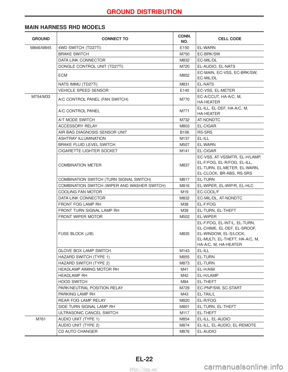
MAIN HARNESS RHD MODELS
GROUNDCONNECT TO CONN.
NO. CELL CODE
M846/M845 4WD SWITCH (TD27Ti) E150 EL-WARN
BRAKE SWITCH M750 EC-BRK/SW
DATA LINK CONNECTOR M832 EC-MIL/DL
DONGLE CONTROL UNIT (TD27Ti) M720 EL-AUDIO, EL-NATS
ECM M852EC-MAIN, EC-VSS, EC-BRK/SW,
EC-MIL/DL
NATS IMMU (TD27Ti) M831 EL-NATS
VEHICLE SPEED SENSOR E140 EC-VSS, EL-METER
M754/M33 A/C CONTROL PANEL (FAN SWITCH) M770EC-A/CCUT, HA-A/C, M,
HA-HEATER
A/C CONTROL PANEL M771EL-ILL, EL-DEF, HA-A/C, M,
HA-HEATER
A/T MODE SWITCH M732 AT-NONDTC
ACCESSORY RELAY M803 EL-CIGAR
AIR BAG DIAGNOSIS SENSOR UNIT B106 RS-SRS
ASHTRAY ILLUMINATION M137 EL-ILL
BRAKE FLUID LEVEL SWITCH M507 EL-WARN
CIGARETTE LIGHTER SOCKET M141 EL-CIGAR
COMBINATION METER M837EC-VSS, AT-VSSMTR, EL-H/LAMP,
EL-F/FOG, EL-R/FOG, EL-ILL,
EL-TURN, EL-METER, EL-WARN,
EL-CLOCK, BR-ABS, RS-SRS
COMBINATION SWITCH (TURN SIGNAL SWITCH) M817 EL-TURN
COMBINATION SWITCH (WIPER AND WASHER SWITCH) M816 EL-WIPER, EL-WIP/R, EL-HLC
COOLING FAN MOTOR M19 EC-COOL/F
DATA LINK CONNECTOR M832 EC-MIL/DL, AT-NONDTC
FRONT FOG LAMP RH M38 EL-F/FOG
FRONT TURN SIGNAL LAMP RH M39 EL-TURN, EL-THEFT
FRONT WIPER MOTOR M502 EL-WIPER
FUSE BLOCK (J/B) M835 EL-F/FOG, EL-INT/L, EL-TURN,
EL-CHIME, EL-DEF, EL-SROOF,
EL-WINDOW, EL-S/LOCK,
EL-MULTI, EL-THEFT, HA-A/C, M,
HA-A/C, M, HA-HEATER
GLOVE BOX LAMP SWITCH M143 EL-ILL
HAZARD SWITCH (TYPE 1) M855 EL-TURN
HAZARD SWITCH (TYPE 2) M873 EL-TURN
HEADLAMP AIMING MOTOR RH M41 EL-H/AIM
HEADLAMP RH M42 EL-H/LAMP
HOOD SWITCH M84 EL-THEFT
PARK/NEUTRAL POSITION RELAY M729 EC-PNP/SW, SC-START
PARKING LAMP RH M43 EL-TAIL/L
REAR FOG LAMP RELAY M820 EL-R/FOG
SIDE TURN SIGNAL LAMP RH M801 EL-TURN, EL-THEFT
ULTRASONIC CANCEL SWITCH M117 EL-THEFT
M761 AUDIO UNIT (TYPE 1) M854 EL-ILL, EL-AUDIO AUDIO UNIT (TYPE 2) M874 EL-ILL, EL-AUDIO, EL-REMOTE
CD AUTO CHANGER M876 EL-AUDIO
GROUND DISTRIBUTION
EL-22
http://vnx.su/
Page 1609 of 1833
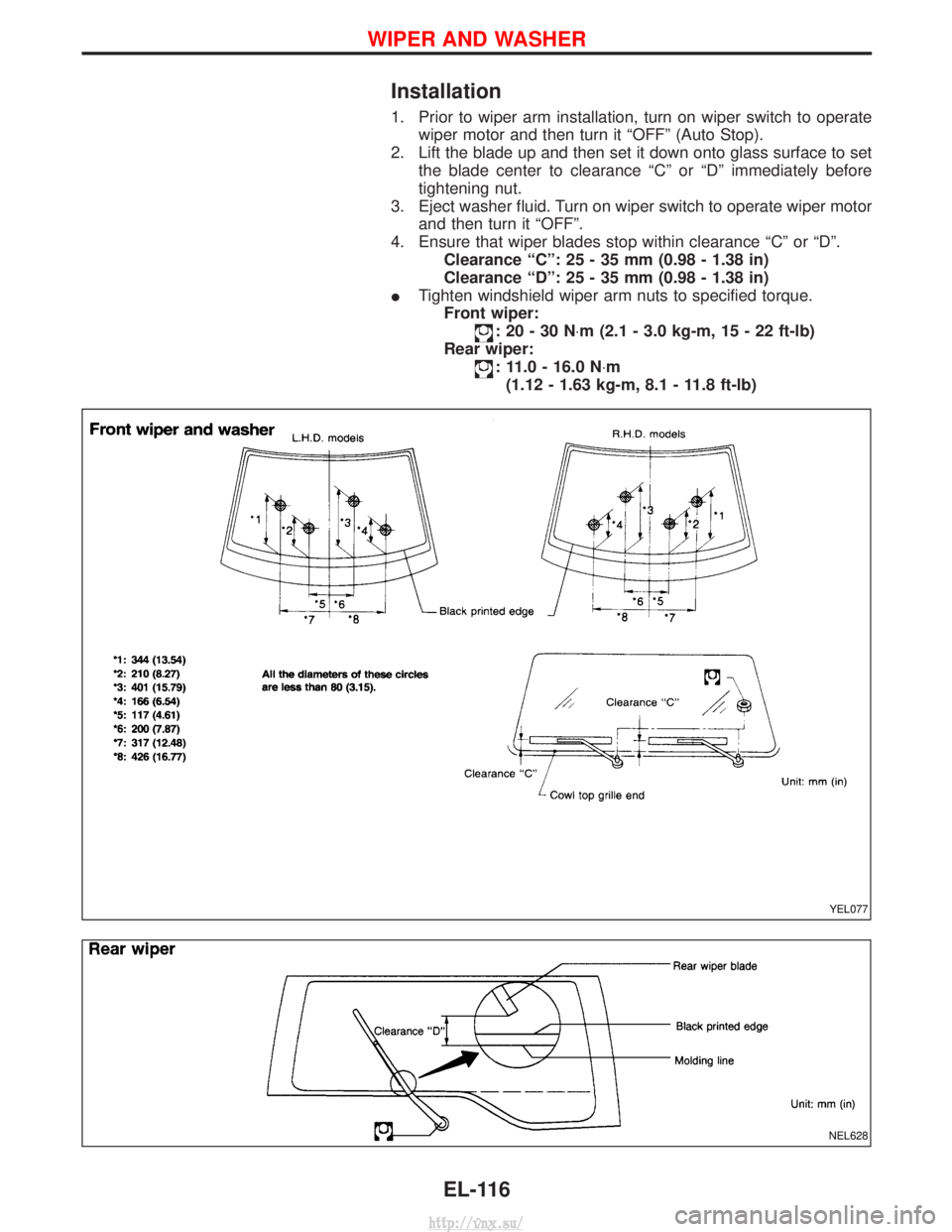
Installation
1. Prior to wiper arm installation, turn on wiper switch to operatewiper motor and then turn it ªOFFº (Auto Stop).
2. Lift the blade up and then set it down onto glass surface to set the blade center to clearance ªCº or ªDº immediately before
tightening nut.
3. Eject washer fluid. Turn on wiper switch to operate wiper motor and then turn it ªOFFº.
4. Ensure that wiper blades stop within clearance ªCº or ªDº. Clearance ªCº: 25 - 35 mm (0.98 - 1.38 in)
Clearance ªDº: 25 - 35 mm (0.98 - 1.38 in)
I Tighten windshield wiper arm nuts to specified torque.
Front wiper:
:20-30N ×m (2.1 - 3.0 kg-m, 15 - 22 ft-lb)
Rear wiper:
: 11.0 - 16.0 N ×m
(1.12 - 1.63 kg-m, 8.1 - 11.8 ft-lb)
YEL077
NEL628
WIPER AND WASHER
EL-116
http://vnx.su/
Page 1610 of 1833
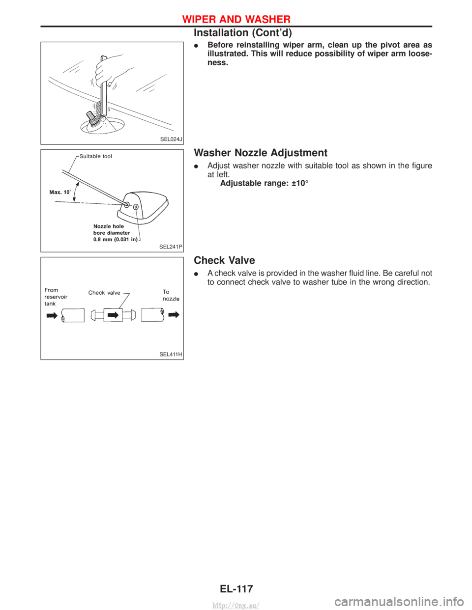
IBefore reinstalling wiper arm, clean up the pivot area as
illustrated. This will reduce possibility of wiper arm loose-
ness.
Washer Nozzle Adjustment
IAdjust washer nozzle with suitable tool as shown in the figure
at left.
Adjustable range: 10É
Check Valve
I A check valve is provided in the washer fluid line. Be careful not
to connect check valve to washer tube in the wrong direction.
SEL024J
SEL241P
SEL411H
WIPER AND WASHER
Installation (Cont'd)
EL-117
http://vnx.su/