water pump NISSAN TERRANO 2004 Service Repair Manual
[x] Cancel search | Manufacturer: NISSAN, Model Year: 2004, Model line: TERRANO, Model: NISSAN TERRANO 2004Pages: 1833, PDF Size: 53.42 MB
Page 65 of 1833
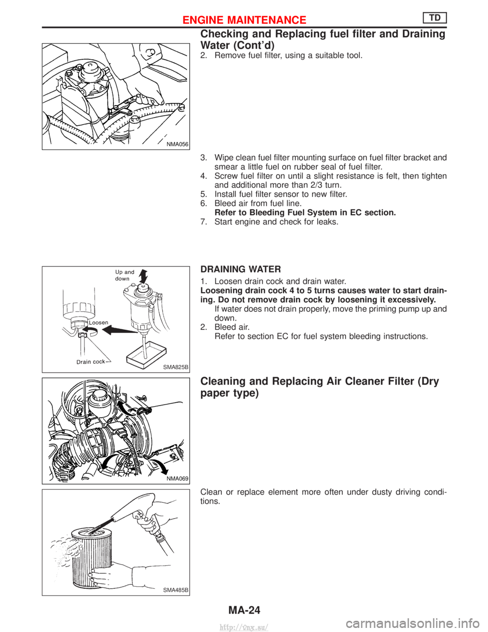
2. Remove fuel filter, using a suitable tool.
3. Wipe clean fuel filter mounting surface on fuel filter bracket andsmear a little fuel on rubber seal of fuel filter.
4. Screw fuel filter on until a slight resistance is felt, then tighten and additional more than 2/3 turn.
5. Install fuel filter sensor to new filter.
6. Bleed air from fuel line. Refer to Bleeding Fuel System in EC section.
7. Start engine and check for leaks.
DRAINING WATER
1. Loosen drain cock and drain water.
Loosening drain cock 4 to 5 turns causes water to start drain-
ing. Do not remove drain cock by loosening it excessively. If water does not drain properly, move the priming pump up and
down.
2. Bleed air. Refer to section EC for fuel system bleeding instructions.
Cleaning and Replacing Air Cleaner Filter (Dry
paper type)
Clean or replace element more often under dusty driving condi-
tions.
NMA056
SMA825B
NMA069
SMA485B
ENGINE MAINTENANCETD
Checking and Replacing fuel filter and Draining
Water (Cont'd)
MA-24
http://vnx.su/
Page 69 of 1833
Checking Tightening Torque
Checking should be performed while engine is cold.
MANIFOLD BOLTS AND NUTS
Intake and exhaust manifolds:Intake
:25-28N ×m (2.5 - 2.9 kg-m, 18 - 20 ft-lb)
Exhaust
:40-44N ×m (4.0 - 4.5 kg-m, 29 - 32 ft-lb)
Adjusting Intake and Exhaust Valve Clearance
Refer to EM section.
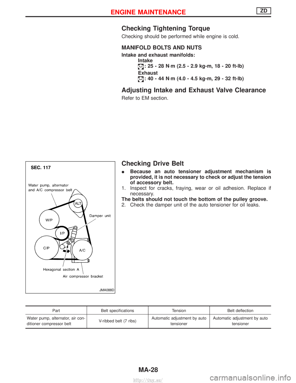
Checking Drive Belt
IBecause an auto tensioner adjustment mechanism is
provided, it is not necessary to check or adjust the tension
of accessory belt.
1. Inspect for cracks, fraying, wear or oil adhesion. Replace if necessary.
The belts should not touch the bottom of the pulley groove.
2. Check the damper unit of the auto tensioner for oil leaks.
Part Belt specifications TensionBelt deflection
Water pump, alternator, air con-
ditioner compressor belt V-ribbed belt (7 ribs)Automatic adjustment by auto
tensioner Automatic adjustment by auto
tensioner
JMA088D
ENGINE MAINTENANCEZD
MA-28
http://vnx.su/
Page 70 of 1833
Removal
WATER PUMP, ALTERNATOR AND AIR CONDITIONER
BELT
1. Remove radiator shroud.
2. Contract and hold the auto tensioner using the following proce-dure.
a. Securely hold the 19 mm (0.75 in) hexagonal portion A of auto tensioner with a closed wrench.
I Preferably use a tool with a handhold of 500 mm (19.69 in) or
more in length.
I No bolts or nuts are required to be loosened during the opera-
tion.
b. Turn the hexagonal portion A in the direction shown by the arrow to contract the damper unit of the auto tensioner.
CAUTION:
I Because the tensioner has a high tension, it shall be
securely held and turned with a closed wrench.
I Because the hexagonal portion A of the tensioner is made
of aluminum and may be damaged by sudden input, turn
it slowly according to the contraction of the damper unit.
3. Remove the belt from the alternator pulley first, and then remove it from the other pulleys.
I If the tensioner is not held firmly, your finger may get caught
between the belt and the pulleys. Confirm the holding of the
tensioner, and then hold the belt side in the place away from
the pulleys to attach or remove the belt, paying attention to
prevent your finger from being caught.
CAUTION:
I When handling the belt, pay attention to prevent the oil or
coolant from adhering to the belt.
I Do not distort or bend the belt intensively.
Installation
IInstall the belt in the reverse order of removal.
I After installation of the belt, confirm that the belt engages the
pulleys securely.
I Depending on the engagement between the belt and the idler
pulley, noise (belt noise) may be heard when the engine is
started just after installation. This noise will stop with time.
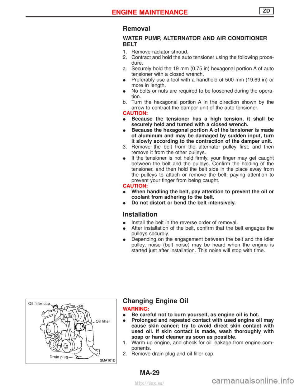
Changing Engine Oil
WARNING:
IBe careful not to burn yourself, as engine oil is hot.
I Prolonged and repeated contact with used engine oil may
cause skin cancer; try to avoid direct skin contact with
used oil. If skin contact is made, wash thoroughly with
soap or hand cleaner as soon as possible.
1. Warm up engine, and check for oil leakage from engine com- ponents.
2. Remove drain plug and oil filler cap.
SMA101D
ENGINE MAINTENANCEZD
MA-29
http://vnx.su/
Page 75 of 1833
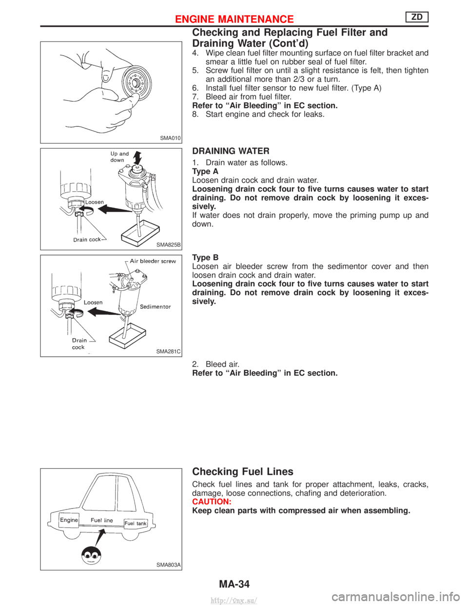
4. Wipe clean fuel filter mounting surface on fuel filter bracket andsmear a little fuel on rubber seal of fuel filter.
5. Screw fuel filter on until a slight resistance is felt, then tighten an additional more than 2/3 or a turn.
6. Install fuel filter sensor to new fuel filter. (Type A)
7. Bleed air from fuel filter.
Refer to ªAir Bleedingº in EC section.
8. Start engine and check for leaks.
DRAINING WATER
1. Drain water as follows.
Type A
Loosen drain cock and drain water.
Loosening drain cock four to five turns causes water to start
draining. Do not remove drain cock by loosening it exces-
sively.
If water does not drain properly, move the priming pump up and
down.
Type B
Loosen air bleeder screw from the sedimentor cover and then
loosen drain cock and drain water.
Loosening drain cock four to five turns causes water to start
draining. Do not remove drain cock by loosening it exces-
sively.
2. Bleed air.
Refer to ªAir Bleedingº in EC section.
Checking Fuel Lines
Check fuel lines and tank for proper attachment, leaks, cracks,
damage, loose connections, chafing and deterioration.
CAUTION:
Keep clean parts with compressed air when assembling.
SMA010
SMA825B
SMA281C
SMA803A
ENGINE MAINTENANCEZD
Checking and Replacing Fuel Filter and
Draining Water (Cont'd)
MA-34
http://vnx.su/
Page 100 of 1833
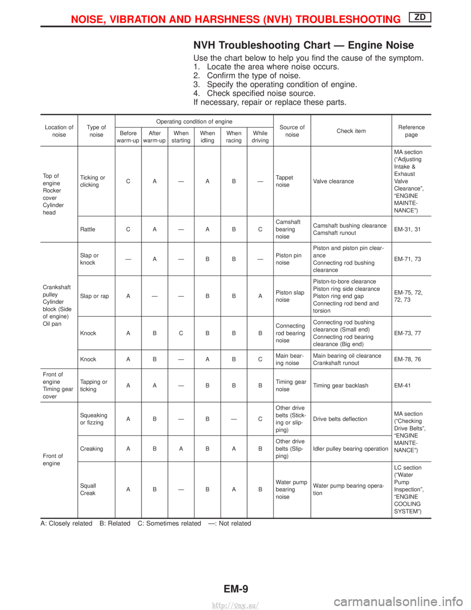
NVH Troubleshooting Chart Ð Engine Noise
Use the chart below to help you find the cause of the symptom.
1. Locate the area where noise occurs.
2. Confirm the type of noise.
3. Specify the operating condition of engine.
4. Check specified noise source.
If necessary, repair or replace these parts.
Location ofnoise Type of
noise Operating condition of engine
Source of
noise Check item Reference
page
Before
warm-up After
warm-up When
starting When
idling When
racing While
driving
To p o f
engine
Rocker
cover
Cylinder
head Ticking or
clicking
C AÐA BÐ Tappet
noiseValve clearance MA section
(ªAdjusting
Intake &
Exhaust
Valve
Clearanceº,
ªENGINE
MAINTE-
NANCEº)
Rattle C A Ð A B C Camshaft
bearing
noiseCamshaft bushing clearance
Camshaft runout
EM-31, 31
Crankshaft
pulley
Cylinder
block (Side
of engine)
Oil pan Slap or
knock
ÐAÐB BÐ Piston pin
noisePiston and piston pin clear-
ance
Connecting rod bushing
clearance
EM-71, 73
Slap or rap A Ð Ð B B A Piston slap
noisePiston-to-bore clearance
Piston ring side clearance
Piston ring end gap
Connecting rod bend and
torsion EM-75, 72,
72, 73
Knock A B C B B B Connecting
rod bearing
noiseConnecting rod bushing
clearance (Small end)
Connecting rod bearing
clearance (Big end)
EM-73, 77
Knock A B Ð A B C Main bear-
ing noiseMain bearing oil clearance
Crankshaft runout
EM-78, 76
Front of
engine
Timing gear
cover Tapping or
ticking
AAÐBBB Timing gear
noiseTiming gear backlash EM-41
Front of
engine Squeaking
or fizzing
A BÐBÐC Other drive
belts (Stick-
ing or slip-
ping)Drive belts deflection
MA section
(ªChecking
Drive Beltsº,
ªENGINE
MAINTE-
NANCEº)
Creaking
ABABAB Other drive
belts (Slip-
ping)Idler pulley bearing operation
Squall
Creak ABÐBAB Water pump
bearing
noiseWater pump bearing opera-
tion LC section
(ªWater
Pump
Inspectionº,
ªENGINE
COOLING
SYSTEMº)
A: Closely related B: Related C: Sometimes related Ð: Not related
NOISE, VIBRATION AND HARSHNESS (NVH) TROUBLESHOOTINGZD
EM-9
http://vnx.su/
Page 117 of 1833
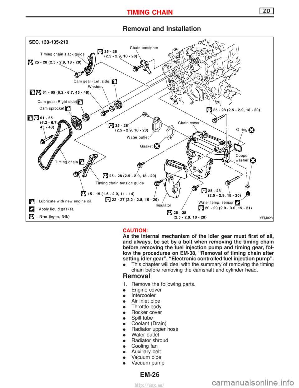
Removal and Installation
CAUTION:
As the internal mechanism of the idler gear must first of all,
and always, be set by a bolt when removing the timing chain
before removing the fuel injection pump and timing gear, fol-
low the procedures on EM-38, ªRemoval of timing chain after
setting idler gearº, ªElectronic controlled fuel injection pumpº.
IThis chapter will deal with the summary of removing the timing
chain before removing the camshaft and cylinder head.
Removal
1. Remove the following parts.
IEngine cover
I Intercooler
I Air inlet pipe
I Throttle body
I Rocker cover
I Spill tube
I Coolant (Drain)
I Radiator upper hose
I Water outlet
I Radiator shroud
I Cooling fan
I Auxiliary belt
I Vacuum pipe
I Vacuum pump
YEM028
TIMING CHAINZD
EM-26
http://vnx.su/
Page 130 of 1833
Removal
1. Remove the engine assembly.Refer to ªENGINE REMOVALº, EM-63.
2. Place the engine on an engine stand (SST). Refer to ªCYLINDER BLOCKº, EM-67.
3. Remove the following.
I Auto tensioner bracket
I Air conditioner bracket
I Alternator bracket
I Oil tube
I Vacuum pump
I Rocker cover
I Oil pan (upper, lower)
I Injection tube
I Spill tube
I High pressure nozzle assembly
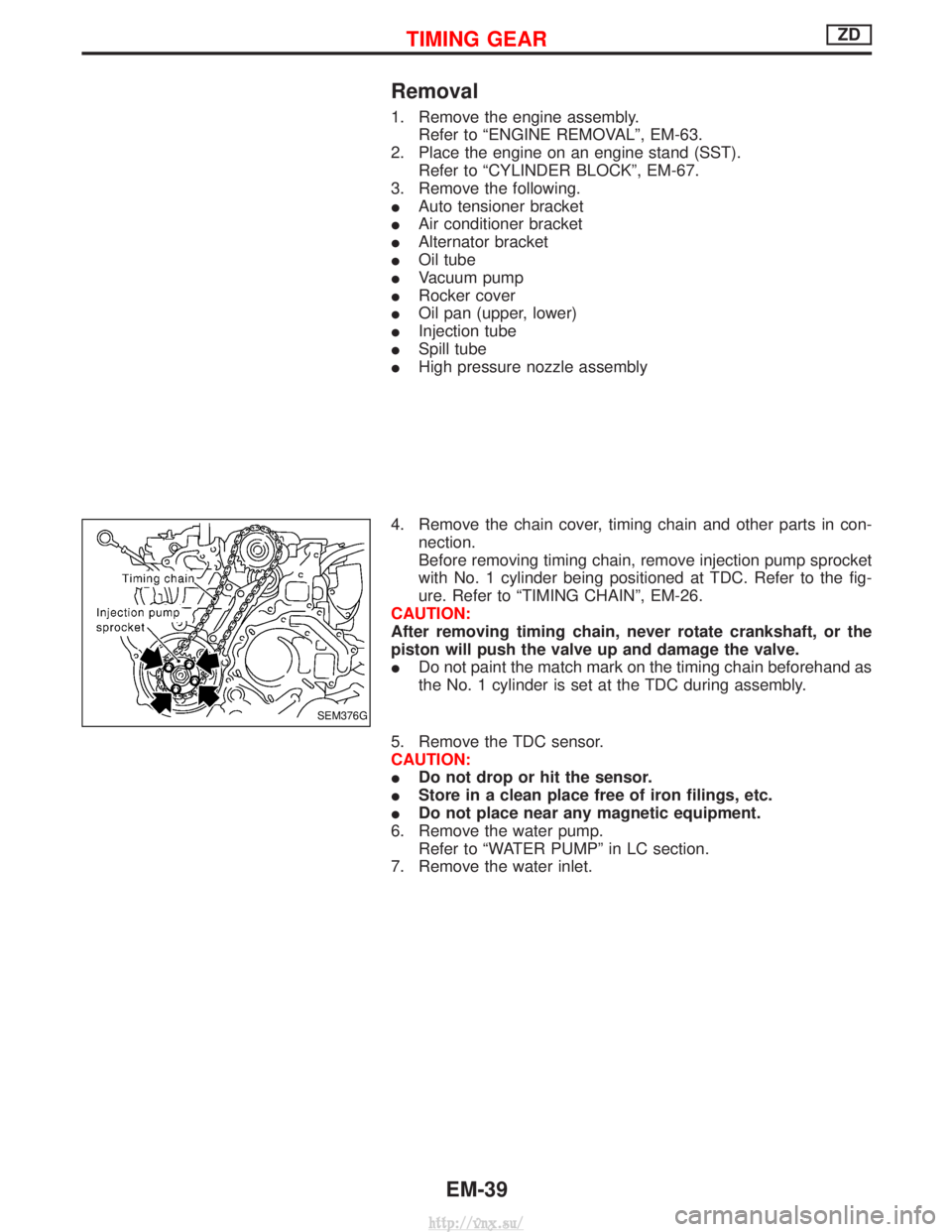
4. Remove the chain cover, timing chain and other parts in con- nection.
Before removing timing chain, remove injection pump sprocket
with No. 1 cylinder being positioned at TDC. Refer to the fig-
ure. Refer to ªTIMING CHAINº, EM-26.
CAUTION:
After removing timing chain, never rotate crankshaft, or the
piston will push the valve up and damage the valve.
I Do not paint the match mark on the timing chain beforehand as
the No. 1 cylinder is set at the TDC during assembly.
5. Remove the TDC sensor.
CAUTION:
I Do not drop or hit the sensor.
I Store in a clean place free of iron filings, etc.
I Do not place near any magnetic equipment.
6. Remove the water pump. Refer to ªWATER PUMPº in LC section.
7. Remove the water inlet.
SEM376G
TIMING GEARZD
EM-39
http://vnx.su/
Page 139 of 1833
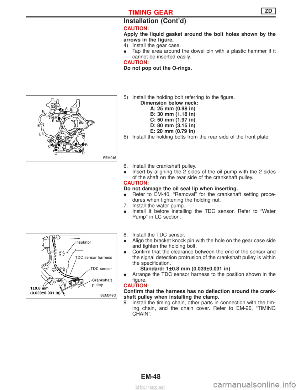
CAUTION:
Apply the liquid gasket around the bolt holes shown by the
arrows in the figure.
4) Install the gear case.
ITap the area around the dowel pin with a plastic hammer if it
cannot be inserted easily.
CAUTION:
Do not pop out the O-rings.
5) Install the holding bolt referring to the figure. Dimension below neck:A: 25 mm (0.98 in)
B: 30 mm (1.18 in)
C: 50 mm (1.97 in)
D: 80 mm (3.15 in)
E: 20 mm (0.79 in)
6) Install the holding bolts from the rear side of the front plate.
6. Install the crankshaft pulley.
I Insert by aligning the 2 sides of the oil pump with the 2 sides
of the shaft on the rear side of the crankshaft pulley.
CAUTION:
Do not damage the oil seal lip when inserting.
I Refer to EM-40, ªRemovalº for the crankshaft setting proce-
dures when tightening the holding nut.
7. Install the water pump.
I Install it before installing the TDC sensor. Refer to ªWater
Pumpº in LC section.
8. Install the TDC sensor.
I Align the bracket knock pin with the hole on the gear case side
and tighten the holding bolt.
I Confirm that the clearance between the end of the sensor and
the signal detection protrusion of the crankshaft pulley is within
the specification.
Standard: 1 0.8 mm (0.039 0.031 in)
I Arrange the TDC sensor harness to the position shown in the
figure.
CAUTION:
Confirm that the harness has no deflection around the crank-
shaft pulley when installing the clamp.
9. Install the timing chain, other parts in connection with the tim- ing chain, and the chain cover. Refer to EM-26, ªTIMING
CHAINº.
FEM046
SEM349G
TIMING GEARZD
Installation (Cont'd)
EM-48
http://vnx.su/
Page 143 of 1833
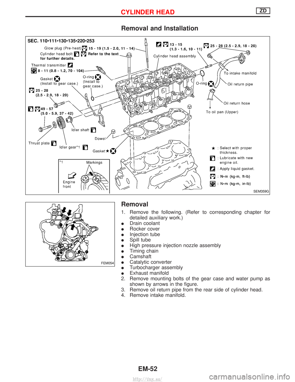
Removal and Installation
Removal
1. Remove the following. (Refer to corresponding chapter fordetailed auxiliary work.)
I Drain coolant
I Rocker cover
I Injection tube
I Spill tube
I High pressure injection nozzle assembly
I Timing chain
I Camshaft
I Catalytic converter
I Turbocharger assembly
I Exhaust manifold
2. Remove mounting bolts of the gear case and water pump as shown by arrows in the figure.
3. Remove oil return pipe from the rear side of cylinder head.
4. Remove intake manifold.
SEM359G
FEM054
CYLINDER HEADZD
EM-52
http://vnx.su/
Page 159 of 1833
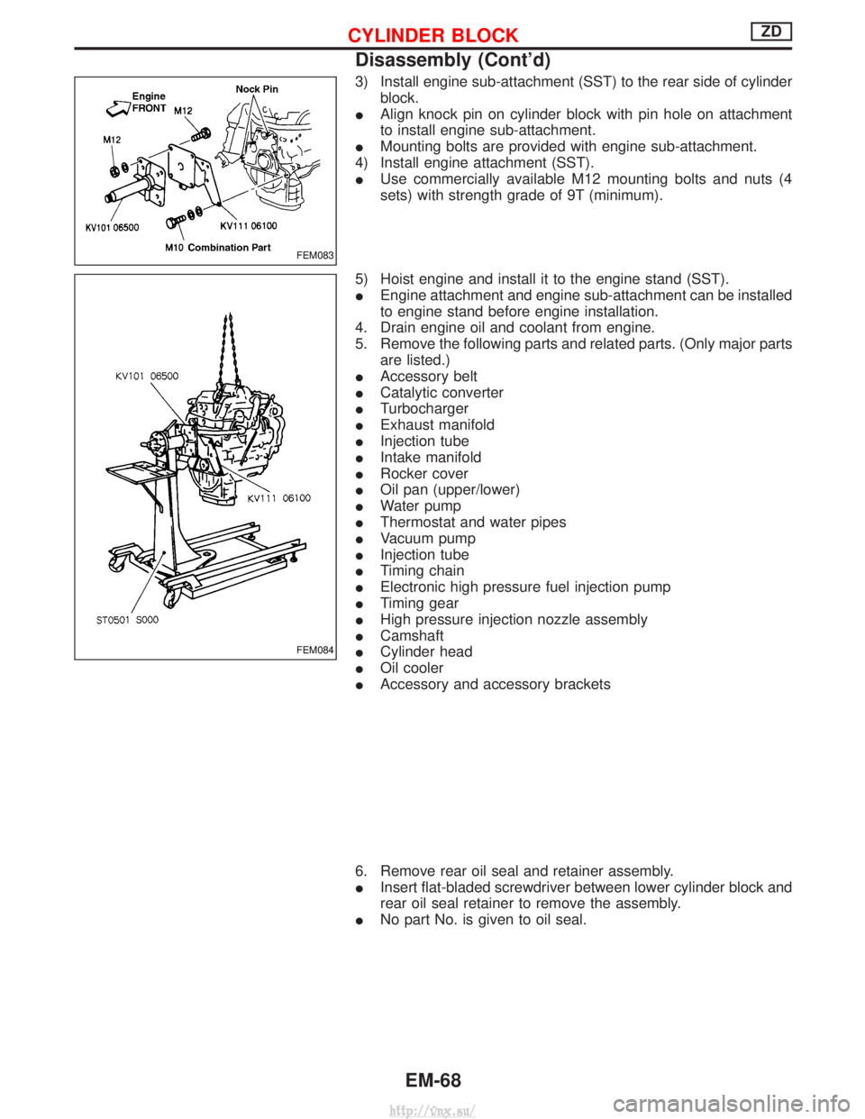
3) Install engine sub-attachment (SST) to the rear side of cylinderblock.
I Align knock pin on cylinder block with pin hole on attachment
to install engine sub-attachment.
I Mounting bolts are provided with engine sub-attachment.
4) Install engine attachment (SST).
I Use commercially available M12 mounting bolts and nuts (4
sets) with strength grade of 9T (minimum).
5) Hoist engine and install it to the engine stand (SST).
I Engine attachment and engine sub-attachment can be installed
to engine stand before engine installation.
4. Drain engine oil and coolant from engine.
5. Remove the following parts and related parts. (Only major parts are listed.)
I Accessory belt
I Catalytic converter
I Turbocharger
I Exhaust manifold
I Injection tube
I Intake manifold
I Rocker cover
I Oil pan (upper/lower)
I Water pump
I Thermostat and water pipes
I Vacuum pump
I Injection tube
I Timing chain
I Electronic high pressure fuel injection pump
I Timing gear
I High pressure injection nozzle assembly
I Camshaft
I Cylinder head
I Oil cooler
I Accessory and accessory brackets
6. Remove rear oil seal and retainer assembly.
I Insert flat-bladed screwdriver between lower cylinder block and
rear oil seal retainer to remove the assembly.
I No part No. is given to oil seal.
FEM083
FEM084
CYLINDER BLOCKZD
Disassembly (Cont'd)
EM-68
http://vnx.su/