fog NISSAN TIIDA 2007 Service User Guide
[x] Cancel search | Manufacturer: NISSAN, Model Year: 2007, Model line: TIIDA, Model: NISSAN TIIDA 2007Pages: 5883, PDF Size: 78.95 MB
Page 159 of 5883
BCS-24
< FUNCTION DIAGNOSIS >
DIAGNOSIS SYSTEM (BCM)
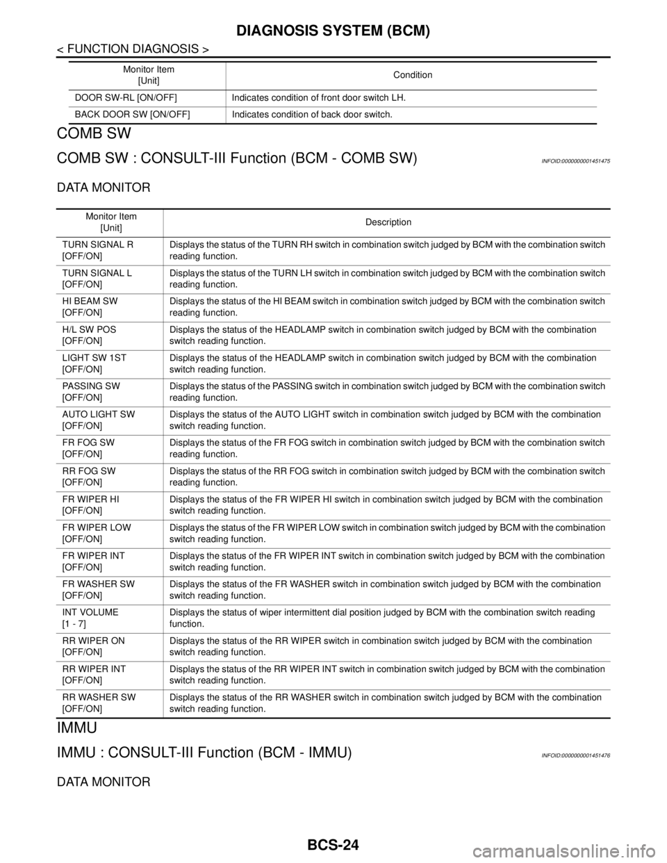
COMB SW
COMB SW : CONSULT-III Function (BCM - COMB SW)INFOID:0000000001451475
DATA MONITOR
IMMU
IMMU : CONSULT-III Function (BCM - IMMU)INFOID:0000000001451476
DATA MONITOR
DOOR SW-RL [ON/OFF] Indicates condition of front door switch LH.
BACK DOOR SW [ON/OFF] Indicates condition of back door switch.Monitor Item
[Unit]Condition
Monitor Item
[Unit]Description
TURN SIGNAL R
[OFF/ON]Displays the status of the TURN RH switch in combination switch judged by BCM with the combination switch
reading function.
TURN SIGNAL L
[OFF/ON]Displays the status of the TURN LH switch in combination switch judged by BCM with the combination switch
reading function.
HI BEAM SW
[OFF/ON]Displays the status of the HI BEAM switch in combination switch judged by BCM with the combination switch
reading function.
H/L SW POS
[OFF/ON]Displays the status of the HEADLAMP switch in combination switch judged by BCM with the combination
switch reading function.
LIGHT SW 1ST
[OFF/ON]Displays the status of the HEADLAMP switch in combination switch judged by BCM with the combination
switch reading function.
PASSING SW
[OFF/ON]Displays the status of the PASSING switch in combination switch judged by BCM with the combination switch
reading function.
AUTO LIGHT SW
[OFF/ON]Displays the status of the AUTO LIGHT switch in combination switch judged by BCM with the combination
switch reading function.
FR FOG SW
[OFF/ON]Displays the status of the FR FOG switch in combination switch judged by BCM with the combination switch
reading function.
RR FOG SW
[OFF/ON]Displays the status of the RR FOG switch in combination switch judged by BCM with the combination switch
reading function.
FR WIPER HI
[OFF/ON]Displays the status of the FR WIPER HI switch in combination switch judged by BCM with the combination
switch reading function.
FR WIPER LOW
[OFF/ON]Displays the status of the FR WIPER LOW switch in combination switch judged by BCM with the combination
switch reading function.
FR WIPER INT
[OFF/ON]Displays the status of the FR WIPER INT switch in combination switch judged by BCM with the combination
switch reading function.
FR WASHER SW
[OFF/ON]Displays the status of the FR WASHER switch in combination switch judged by BCM with the combination
switch reading function.
INT VOLUME
[1 - 7]Displays the status of wiper intermittent dial position judged by BCM with the combination switch reading
function.
RR WIPER ON
[OFF/ON]Displays the status of the RR WIPER switch in combination switch judged by BCM with the combination
switch reading function.
RR WIPER INT
[OFF/ON]Displays the status of the RR WIPER INT switch in combination switch judged by BCM with the combination
switch reading function.
RR WASHER SW
[OFF/ON]Displays the status of the RR WASHER switch in combination switch judged by BCM with the combination
switch reading function.
Page 169 of 5883
BCS-34
< COMPONENT DIAGNOSIS >
COMBINATION SWITCH
COMBINATION SWITCH
DescriptionINFOID:0000000001451493
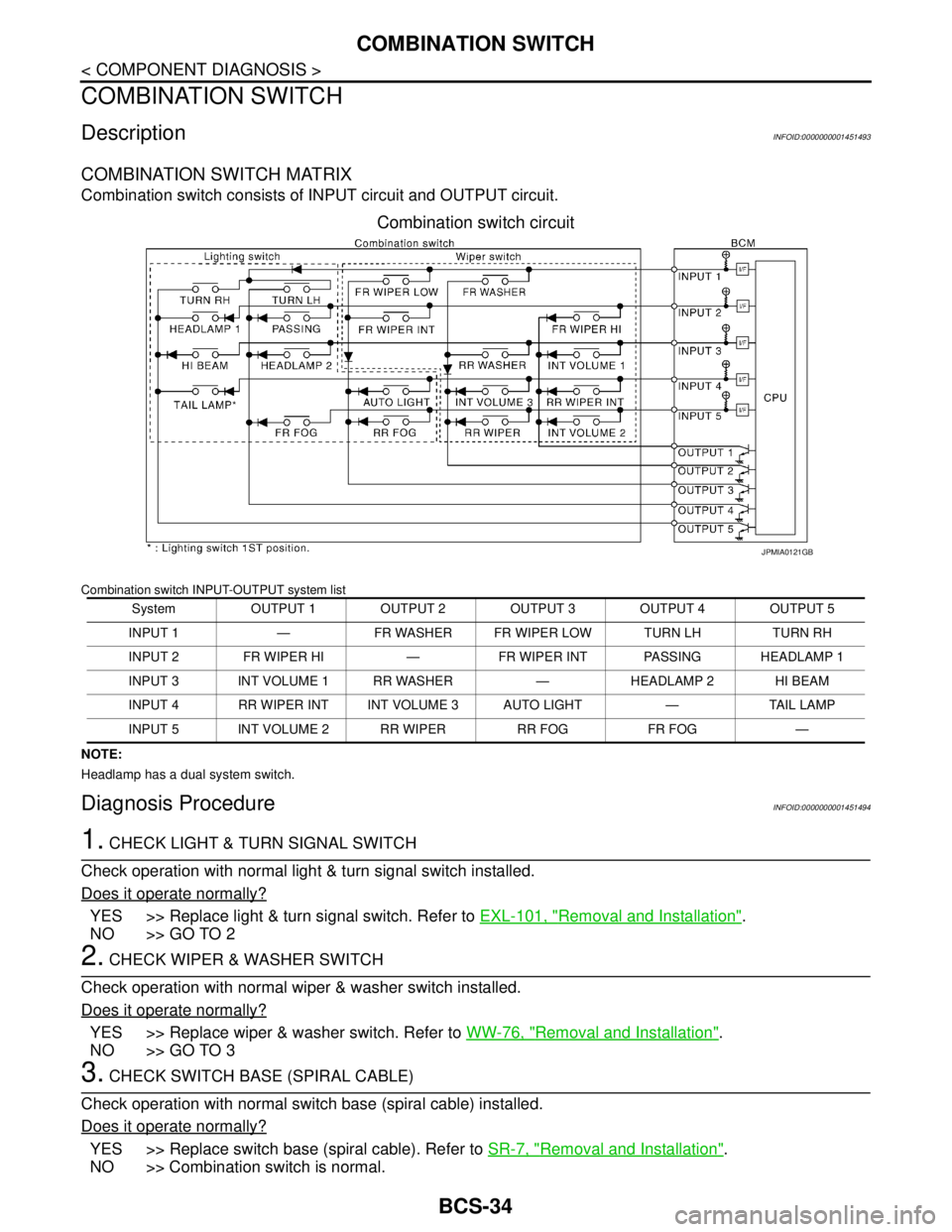
COMBINATION SWITCH MATRIX
Combination switch consists of INPUT circuit and OUTPUT circuit.
Combination switch circuit
Combination switch INPUT-OUTPUT system list
NOTE:
Headlamp has a dual system switch.
Diagnosis ProcedureINFOID:0000000001451494
1. CHECK LIGHT & TURN SIGNAL SWITCH
Check operation with normal light & turn signal switch installed.
Does it operate normally?
YES >> Replace light & turn signal switch. Refer to EXL-101, "Removal and Installation".
NO >> GO TO 2
2. CHECK WIPER & WASHER SWITCH
Check operation with normal wiper & washer switch installed.
Does it operate normally?
YES >> Replace wiper & washer switch. Refer to WW-76, "Removal and Installation".
NO >> GO TO 3
3. CHECK SWITCH BASE (SPIRAL CABLE)
Check operation with normal switch base (spiral cable) installed.
Does it operate normally?
YES >> Replace switch base (spiral cable). Refer to SR-7, "Removal and Installation".
NO >> Combination switch is normal.
System OUTPUT 1 OUTPUT 2 OUTPUT 3 OUTPUT 4 OUTPUT 5
INPUT 1 — FR WASHER FR WIPER LOW TURN LH TURN RH
INPUT 2 FR WIPER HI — FR WIPER INT PASSING HEADLAMP 1
INPUT 3 INT VOLUME 1 RR WASHER — HEADLAMP 2 HI BEAM
INPUT 4 RR WIPER INT INT VOLUME 3 AUTO LIGHT — TAIL LAMP
INPUT 5 INT VOLUME 2 RR WIPER RR FOG FR FOG —
JPMIA0121GB
Page 171 of 5883
BCS-36
< ECU DIAGNOSIS >
BCM (BODY CONTROL MODULE)
ENGINE RPM
NOTE:
Diesel engine models
onlyEngine runningApproximately the same as tachom-
eter reading
ENGINE RUNEngine stopped OFF
Engine running ON
ENGINE STATUS
NOTE:
Diesel engine models
onlyEngine stopped STOP
While the engine stalls STALL
Engine running RUN
At engine cranking CRA
FA N O N S I GFan switch OFF OFF
Fan switch ON ON
FR FOG SWFront fog lamp switch OFF OFF
Front fog lamp switch ON ON
FR WASHER SWFront washer switch OFF OFF
Front washer switch ON ON
FR WIPER LOWFront wiper switch OFF OFF
Front wiper switch LO ON
FR WIPER HIFront wiper switch OFF OFF
Front wiper switch HI ON
FR WIPER INTFront wiper switch OFF OFF
Front wiper switch INT ON
FR WIPER STOPAny position other than front wiper stop position OFF
Front wiper stop position ON
HAZARD SWWhen hazard switch is not pressed OFF
When hazard switch is pressed ON
LIGHT SW 1STLighting switch OFF OFF
Lighting switch 1st ON
H/L SW POSHeadlamp switch OFF OFF
Headlamp switch 1st ON
HI BEAM SWHigh beam switch OFF OFF
High beam switch HI ON
HOOD SWClose the hood
NOTE:
Vehicles without theft warning system are OFF-fixedOFF
Open the hood ON
H/L WASH SWNOTE:
The item is indicated, but not monitoredOFF
IGN ON SWIgnition switch OFF or ACC OFF
Ignition switch ON ON
IGN SW CANIgnition switch OFF or ACC OFF
Ignition switch ON ON
INT VOLUME Wiper intermittent dial is in a dial position 1 - 7 1 - 7
I-KEY LOCK
1LOCK button of Intelligent Key is not pressed OFF
LOCK button of Intelligent Key is pressed ON Monitor Item Condition Value/Status
Page 172 of 5883
BCS
BCM (BODY CONTROL MODULE)
BCS-37
< ECU DIAGNOSIS >
C
D
E
F
G
H
I
J
K
L B A
O
P N
I-KEY UNLOCK1UNLOCK button of Intelligent Key is not pressed OFF
UNLOCK button of Intelligent Key is pressed ON
KEY SW
2Mechanical key is removed from key cylinder OFF
Mechanical key is inserted to key cylinder ON
KEYLESS LOCK
2LOCK button of key fob is not pressed OFF
LOCK button of key fob is pressed ON
KEYLESS UNLOCK
2UNLOCK button of key fob is not pressed OFF
UNLOCK button of key fob is pressed ON
LIT-SEN FAILLight & rain sensor is in normal condition OK
Light & rain sensor is with internal error NOTOK
OIL PRESS SW Ignition switch OFF or ACC
Engine runningOFF
Ignition switch ON ON
OUT SIDE TEMP
NOTE:
Diesel engine modelsIgnition switch ONApproximately the same as outside
air temperature
PASSING SWOther than lighting switch PASS OFF
Lighting switch PASS ON
PUSH SW
1Return to ignition switch to LOCK position OFF
Press ignition switch ON
REAR DEF SWRear window defogger switch OFF OFF
Rear window defogger switch ON ON
RKE LOCK AND
UNLOCK
2NOTE:
The item is indicated, but not monitoredOFF
ON
RR FOG SWRear fog lamp switch OFF OFF
Rear fog lamp switch ON ON
RR WASHER SW
3Rear washer switch OFF OFF
Rear washer switch ON ON
RR WIPER INT
3Rear wiper switch OFF OFF
Rear wiper switch INT ON
RR WIPER ON
3 Rear wiper switch OFF OFF
Rear wiper switch ON ON
RR WIPER STOP
3Rear wiper stop position OFF
Other than rear wiper stop position ON
TAIL LAMP SWLighting switch OFF OFF
Lighting switch 1ST ON
TRNK OPNR SWWhen back door opener switch is not pressed OFF
When back door opener switch is pressed ON
TURN SIGNAL LTurn signal switch OFF OFF
Turn signal switch LH ON
TURN SIGNAL RTurn signal switch OFF OFF
Turn signal switch RH ON
UNLOCK WITH DRNOTE:
The item is indicated, but not monitoredOFF
ON
VEHICLE SPEED While driving Equivalent to speedometer reading Monitor Item Condition Value/Status
Page 174 of 5883
BCS
BCM (BODY CONTROL MODULE)
BCS-39
< ECU DIAGNOSIS >
C
D
E
F
G
H
I
J
K
L B A
O
P N
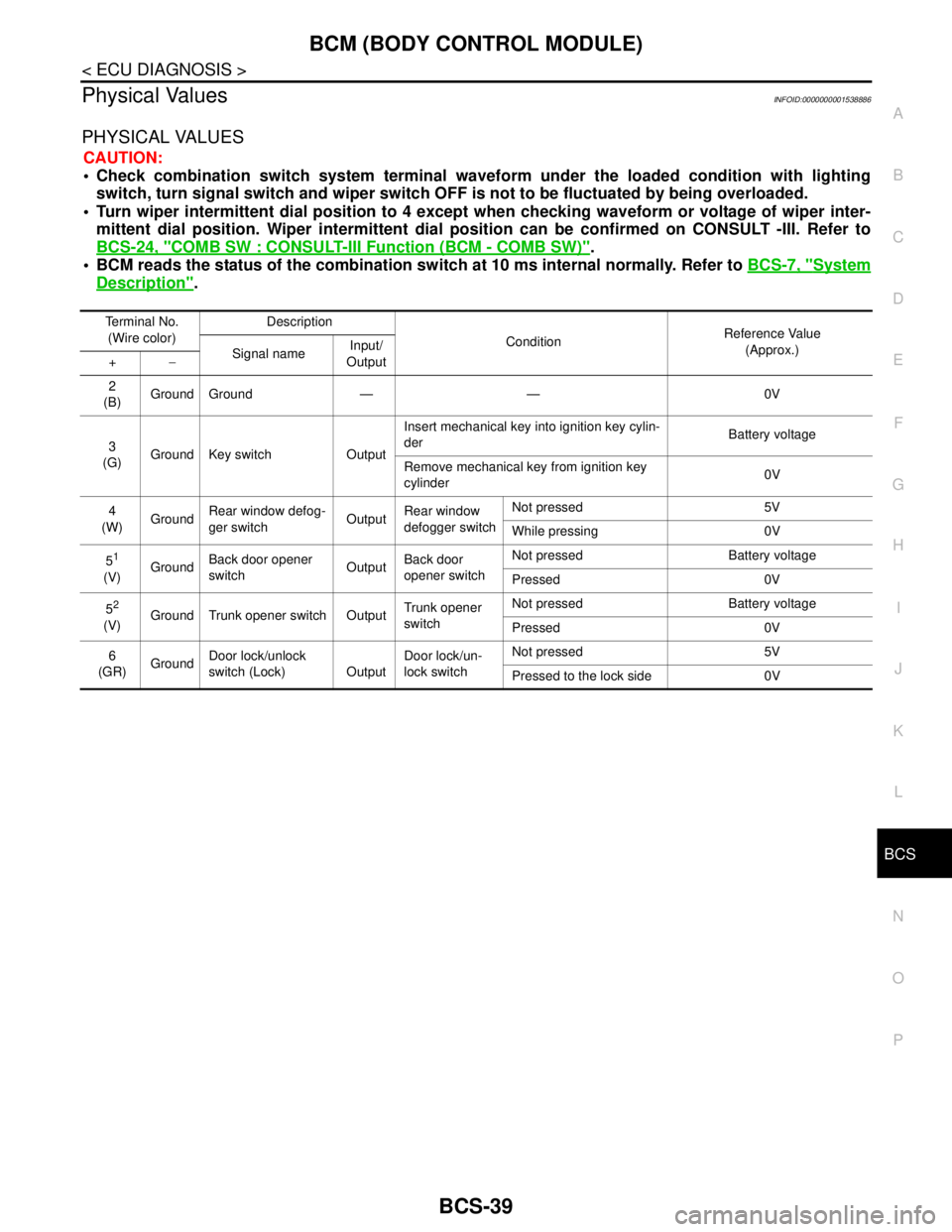
Physical ValuesINFOID:0000000001538886
PHYSICAL VALUES
CAUTION:
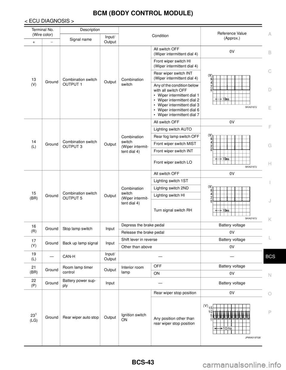
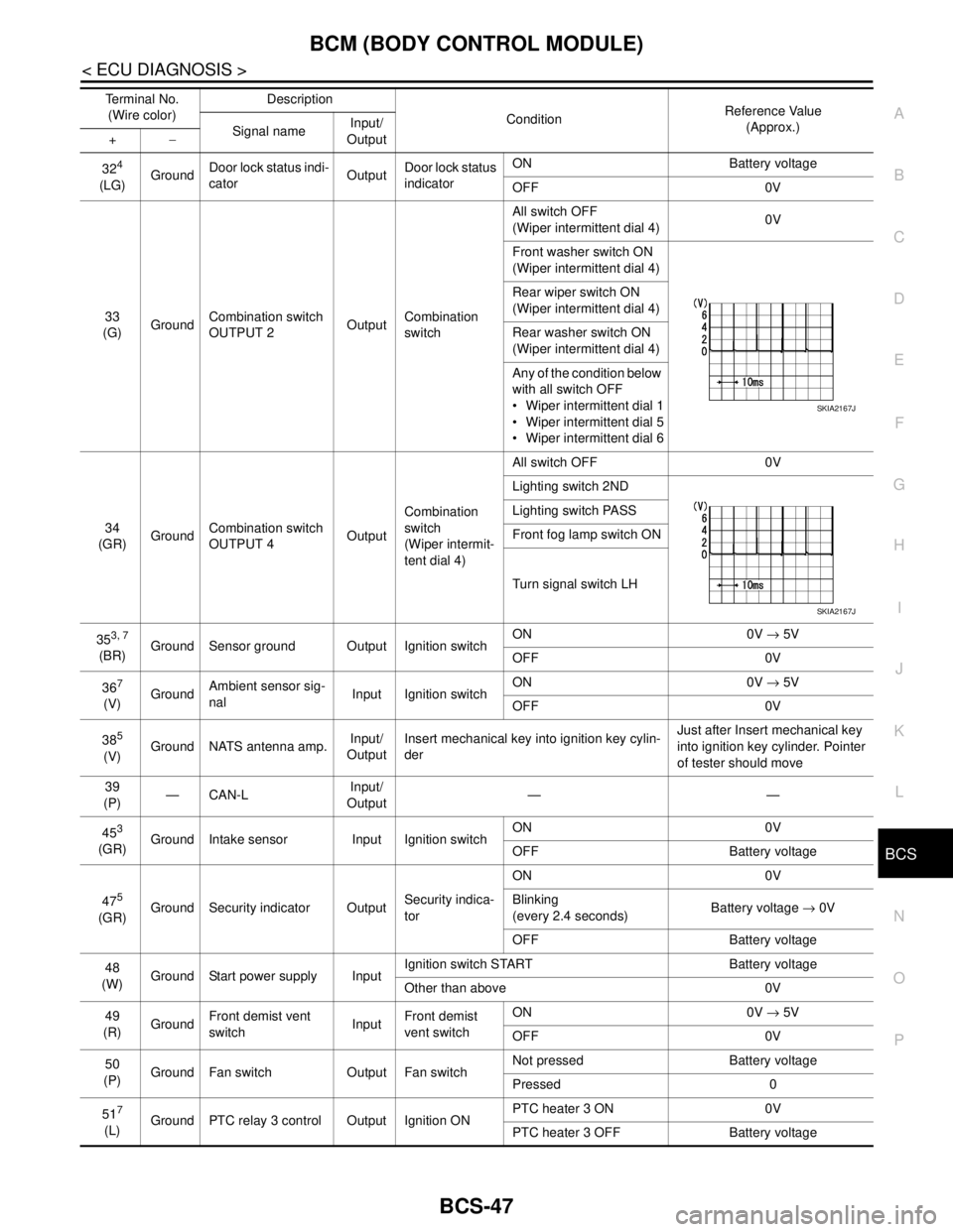
Check combination switch system terminal waveform under the loaded condition with lighting
switch, turn signal switch and wiper switch OFF is not to be fluctuated by being overloaded.
Turn wiper intermittent dial position to 4 except when checking waveform or voltage of wiper inter-
mittent dial position. Wiper intermittent dial position can be confirmed on CONSULT -III. Refer to
BCS-24, "
COMB SW : CONSULT-III Function (BCM - COMB SW)".
BCM reads the status of the combination switch at 10 ms internal normally. Refer to BCS-7, "
System
Description".
Terminal No.
(Wire color)Description
ConditionReference Value
(Approx.)
Signal nameInput/
Output +−
2
(B)Ground Ground — — 0V
3
(G)Ground Key switch OutputInsert mechanical key into ignition key cylin-
derBattery voltage
Remove mechanical key from ignition key
cylinder0V
4
(W)GroundRear window defog-
ger switchOutputRear window
defogger switchNot pressed 5V
While pressing 0V
5
1
(V)GroundBack door opener
switchOutputBack door
opener switchNot pressed Battery voltage
Pressed 0V
5
2
(V)Ground Trunk opener switch OutputTrunk opener
switchNot pressed Battery voltage
Pressed 0V
6
(GR)GroundDoor lock/unlock
switch (Lock) OutputDoor lock/un-
lock switchNot pressed 5V
Pressed to the lock side 0V
Page 175 of 5883

BCS-40
< ECU DIAGNOSIS >
BCM (BODY CONTROL MODULE)
7
(LG)GroundCombination switch
INPUT 5InputCombination
switchAll switch OFF
(Wiper intermittent dial 4)
1.3V
Front fog lamp switch ON
(Wiper intermittent dial 4)
1.3V
Rear fog lamp switch ON
(Wiper intermittent dial 4)
1.3V
Rear wiper switch ON
(Wiper intermittent dial 4)
1.3V
Any of the condition below
with all switch OFF
Wiper intermittent dial 1
Wiper intermittent dial 2
Wiper intermittent dial 6
Wiper intermittent dial 7
1.3V Te r m i n a l N o .
(Wire color)Description
ConditionReference Value
(Approx.)
Signal nameInput/
Output +−
JPMIA0165GB
JPMIA0167GB
JPMIA0168GB
JPMIA0169GB
JPMIA0196GB
Page 178 of 5883
BCS
BCM (BODY CONTROL MODULE)
BCS-43
< ECU DIAGNOSIS >
C
D
E
F
G
H
I
J
K
L B A
O
P N
13
(V)GroundCombination switch
OUTPUT 1OutputCombination
switchAll switch OFF
(Wiper intermittent dial 4)0V
Front wiper switch HI
(Wiper intermittent dial 4)
Rear wiper switch INT
(Wiper intermittent dial 4)
Any of the condition below
with all switch OFF
Wiper intermittent dial 1
Wiper intermittent dial 2
Wiper intermittent dial 3
Wiper intermittent dial 6
Wiper intermittent dial 7
14
(L)GroundCombination switch
OUTPUT 3OutputCombination
switch
(Wiper intermit-
tent dial 4)All switch OFF 0V
Lighting switch AUTO
Rear fog lamp switch OFF
Front wiper switch MIST
Front wiper switch INT
Front wiper switch LO
15
(BR)GroundCombination switch
OUTPUT 5OutputCombination
switch
(Wiper intermit-
tent dial 4)All switch OFF 0V
Lighting switch 1ST
Lighting switch 2ND
Lighting switch HI
Turn signal switch RH
16
(R)Ground Stop lamp switch InputDepress the brake pedal Battery voltage
Release the brake pedal 0V
17
(Y)Ground Back up lamp signal InputShift lever in reverse Battery voltage
Other than above 0V
19
(L)—CAN-HInput/
Output——
21
(BR)GroundRoom lamp timer
controlOutputInterior room
lampOFF Battery voltage
ON 0V
22
(P)GroundBattery power sup-
plyInput — Battery voltage
23
1
(LG)Ground Rear wiper auto stop OutputIgnition switch
ONRear wiper stop position 0V
Any position other than
rear wiper stop position Terminal No.
(Wire color)Description
ConditionReference Value
(Approx.)
Signal nameInput/
Output +−
SKIA2167J
SKIA2167J
SKIA2167J
JPMIA0197GB
Page 182 of 5883
BCS
BCM (BODY CONTROL MODULE)
BCS-47
< ECU DIAGNOSIS >
C
D
E
F
G
H
I
J
K
L B A
O
P N
324
(LG)GroundDoor lock status indi-
catorOutputDoor lock status
indicatorON Battery voltage
OFF 0V
33
(G)GroundCombination switch
OUTPUT 2OutputCombination
switchAll switch OFF
(Wiper intermittent dial 4)0V
Front washer switch ON
(Wiper intermittent dial 4)
Rear wiper switch ON
(Wiper intermittent dial 4)
Rear washer switch ON
(Wiper intermittent dial 4)
Any of the condition below
with all switch OFF
Wiper intermittent dial 1
Wiper intermittent dial 5
Wiper intermittent dial 6
34
(GR)GroundCombination switch
OUTPUT 4OutputCombination
switch
(Wiper intermit-
tent dial 4)All switch OFF 0V
Lighting switch 2ND
Lighting switch PASS
Front fog lamp switch ON
Turn signal switch LH
35
3, 7
(BR)Ground Sensor ground Output Ignition switchON 0V → 5V
OFF 0V
36
7
(V)GroundAmbient sensor sig-
nalInput Ignition switchON 0V → 5V
OFF 0V
38
5
(V)Ground NATS antenna amp.Input/
OutputInsert mechanical key into ignition key cylin-
derJust after Insert mechanical key
into ignition key cylinder. Pointer
of tester should move
39
(P)—CAN-LInput/
Output——
45
3
(GR)Ground Intake sensor Input Ignition switchON 0V
OFF Battery voltage
47
5
(GR)Ground Security indicator OutputSecurity indica-
torON 0V
Blinking
(every 2.4 seconds)Battery voltage → 0V
OFF Battery voltage
48
(W)Ground Start power supply InputIgnition switch START Battery voltage
Other than above 0V
49
(R)GroundFront demist vent
switchInputFront demist
vent switchON 0V → 5V
OFF 0V
50
(P)Ground Fan switch Output Fan switchNot pressed Battery voltage
Pressed 0
51
7
(L)Ground PTC relay 3 control Output Ignition ONPTC heater 3 ON 0V
PTC heater 3 OFF Battery voltage Terminal No.
(Wire color)Description
ConditionReference Value
(Approx.)
Signal nameInput/
Output +−
SKIA2167J
SKIA2167J
Page 184 of 5883
BCS
BCM (BODY CONTROL MODULE)
BCS-49
< ECU DIAGNOSIS >
C
D
E
F
G
H
I
J
K
L B A
O
P N
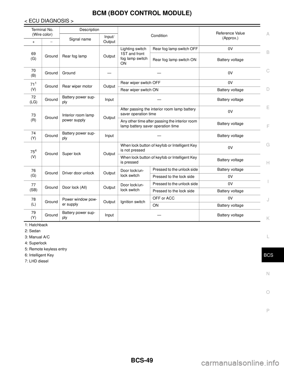
1: Hatchback
2: Sedan
3: Manual A/C
4: Superlock
5: Remote keyless entry
6: Intelligent Key
7: LHD diesel69
(G)Ground Rear fog lamp OutputLighting switch
1ST and front
fog lamp switch
ONRear fog lamp switch OFF 0V
Rear fog lamp switch ON Battery voltage
70
(B)Ground Ground — — 0V
71
1
(V)Ground Rear wiper motor OutputRear wiper switch OFF 0V
Rear wiper switch ON Battery voltage
72
(LG)GroundBattery power sup-
plyInput — Battery voltage
73
(R)GroundInterior room lamp
power supplyOutputAfter passing the interior room lamp battery
saver operation time0V
Any other time after passing the interior room
lamp battery saver operation timeBattery voltage
74
(Y)GroundBattery power sup-
plyInput — Battery voltage
75
4
(V)Ground Super lock OutputWhen lock button of keyfob or Intelligent Key
is not pressed 0V
When lock button of keyfob or Intelligent Key
is pressed Battery voltage
76
(G)Ground Driver door unlock OutputDoor lock/un-
lock switchPressed to the unlock side Battery voltage
Pressed to the lock side 0V
77
(SB)Ground Door lock (All) OutputDoor lock/un-
lock switchPressed to the unlock side 0V
Pressed to the lock side Battery voltage
78
(L)GroundPower window pow-
er supplyOutput Ignition switchOFF or ACC 0V
ON Battery voltage
79
(Y)GroundBattery power sup-
plyInput — Battery voltage Terminal No.
(Wire color)Description
ConditionReference Value
(Approx.)
Signal nameInput/
Output +−
Page 190 of 5883
BCS
COMBINATION SWITCH SYSTEM SYMPTOMS
BCS-55
< SYMPTOM DIAGNOSIS >
C
D
E
F
G
H
I
J
K
L B A
O
P N
SYMPTOM DIAGNOSIS
COMBINATION SWITCH SYSTEM SYMPTOMS
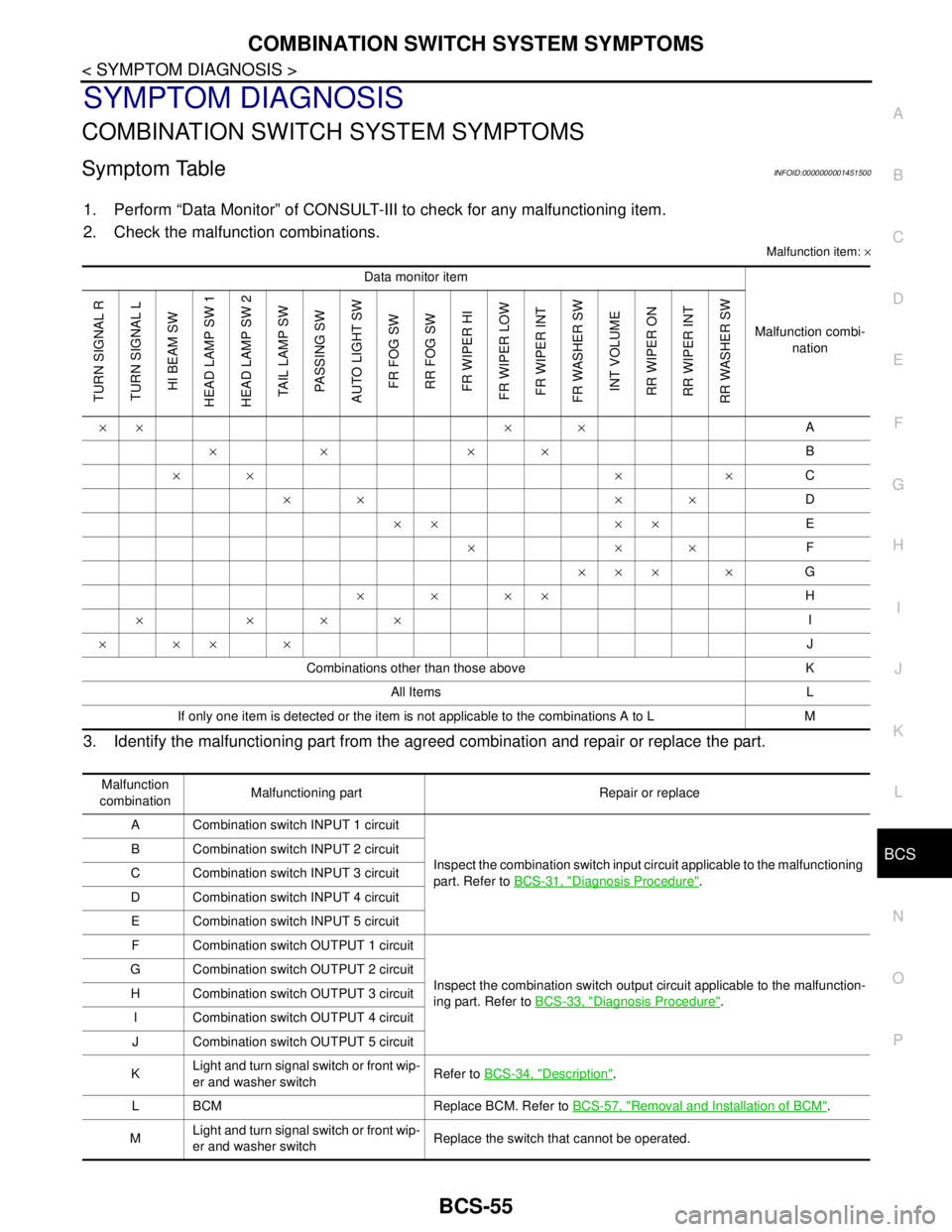
Symptom TableINFOID:0000000001451500
1. Perform “Data Monitor” of CONSULT-III to check for any malfunctioning item.
2. Check the malfunction combinations.
Malfunction item: ×
3. Identify the malfunctioning part from the agreed combination and repair or replace the part.
Data monitor item
Malfunction combi-
nation
TURN SIGNAL R
TURN SIGNAL L
HI BEAM SW
HEAD LAMP SW 1
HEAD LAMP SW 2
TAIL LAMP SW
PASSING SW
AUTO LIGHT SW
FR FOG SW
RR FOG SW
FR WIPER HI
FR WIPER LOW
FR WIPER INT
FR WASHER SW
INT VOLUME
RR WIPER ON
RR WIPER INT
RR WASHER SW
×× × ×A
×× ××B
×× × ×C
×× ××D
×× ××E
×××F
××× ×G
××××H
××××I
××××J
Combinations other than those above K
All Items L
If only one item is detected or the item is not applicable to the combinations A to L M
Malfunction
combinationMalfunctioning part Repair or replace
A Combination switch INPUT 1 circuit
Inspect the combination switch input circuit applicable to the malfunctioning
part. Refer to BCS-31, "
Diagnosis Procedure". B Combination switch INPUT 2 circuit
C Combination switch INPUT 3 circuit
D Combination switch INPUT 4 circuit
E Combination switch INPUT 5 circuit
F Combination switch OUTPUT 1 circuit
Inspect the combination switch output circuit applicable to the malfunction-
ing part. Refer to BCS-33, "
Diagnosis Procedure". G Combination switch OUTPUT 2 circuit
H Combination switch OUTPUT 3 circuit
I Combination switch OUTPUT 4 circuit
J Combination switch OUTPUT 5 circuit
KLight and turn signal switch or front wip-
er and washer switchRefer to BCS-34, "
Description".
L BCM Replace BCM. Refer to BCS-57, "
Removal and Installation of BCM".
MLight and turn signal switch or front wip-
er and washer switchReplace the switch that cannot be operated.