charging NISSAN TIIDA 2007 Service Owner's Guide
[x] Cancel search | Manufacturer: NISSAN, Model Year: 2007, Model line: TIIDA, Model: NISSAN TIIDA 2007Pages: 5883, PDF Size: 78.95 MB
Page 2436 of 5883
![NISSAN TIIDA 2007 Service Owners Guide ENGINE TORQUE CONTROL
EC-1087
< FUNCTION DIAGNOSIS >[K9K]
C
D
E
F
G
H
I
J
K
L
MA
EC
N
P O
ENGINE TORQUE CONTROL
System DescriptionINFOID:0000000001162540
The torque structure is the system which trans NISSAN TIIDA 2007 Service Owners Guide ENGINE TORQUE CONTROL
EC-1087
< FUNCTION DIAGNOSIS >[K9K]
C
D
E
F
G
H
I
J
K
L
MA
EC
N
P O
ENGINE TORQUE CONTROL
System DescriptionINFOID:0000000001162540
The torque structure is the system which trans](/img/5/57395/w960_57395-2435.png)
ENGINE TORQUE CONTROL
EC-1087
< FUNCTION DIAGNOSIS >[K9K]
C
D
E
F
G
H
I
J
K
L
MA
EC
N
P O
ENGINE TORQUE CONTROL
System DescriptionINFOID:0000000001162540
The torque structure is the system which translates the driver's request into a torque supplied by the engine. It
is required for certain functions such as the electronic stability program (ESP), the automatic gearbox or the
sequentialgearbox if fitted).
Each inter-system (ESP, automatic gearbox, sequential gearbox) sends the ECM a torque request viathe CAN
communication. The computer arbitrates between the inter-system torque requests and the driver's request
(comprised of the accelerator pedal or the cruise control/speed limiter function). The result of the arbitration
gives thetorque setpoint.
From this torque setpoint, the computer determines the quantity of fuel to be injected (injection duration and
numberof injections) and the amount of air required (turbocharging pressure and EGR rate) so that the engine
is able toprovide the torque required in the best possible conditions (in terms of smooth running performance,
pollutantemissions, etc.).
Component Parts LocationINFOID:0000000001611148
ALBIA0296ZZ
Page 2573 of 5883
![NISSAN TIIDA 2007 Service Owners Guide EC-1224
< ECU DIAGNOSIS >[K9K]
ECM
Test Condition: Engine Stopped and Ignition Switch ON
Order Function Parameter Display and notes Trouble diagnosis
1 Battery voltage BATTERY VOLTAGE12 V < BATTERY VO NISSAN TIIDA 2007 Service Owners Guide EC-1224
< ECU DIAGNOSIS >[K9K]
ECM
Test Condition: Engine Stopped and Ignition Switch ON
Order Function Parameter Display and notes Trouble diagnosis
1 Battery voltage BATTERY VOLTAGE12 V < BATTERY VO](/img/5/57395/w960_57395-2572.png)
EC-1224
< ECU DIAGNOSIS >[K9K]
ECM
Test Condition: Engine Stopped and Ignition Switch ON
Order Function Parameter Display and notes Trouble diagnosis
1 Battery voltage BATTERY VOLTAGE12 V < BATTERY VOLTAGE <
14.4 VIn the event of a malfunction, per-
form the trouble diagnosis for
CHARGING SYSTEM.
2 Engine speed ENGINE SPEEDIndicates the engine's rotational
speed in rpm.In the event of a malfunction, per-
form the trouble diagnosis for DTC
P0335 CKP SENSOR.
3Engine coolant tem-
peratureWATER TEMPClose to ambient temperature
(cold engine).
Indicates the engine coolant tem-
perature in ° C.In the event of a malfunction, per-
form the trouble diagnosis for DTC
P0115 ETC SENSOR.
4Accelerator pedal po-
sitionACCEL/PDL POS0%= ACCEL/PDL POS < 100%
Indicates the percentage of the
pedal position between no load
and full load positionIn the event of a malfunction, per-
form the trouble diagnosis for APP
SENSOR (DTC P0225, and P2120)
and SENSOR POWER SUPPLY
(DTC P0641 and P0651).
5 Inlet air temperature INLET AIR TEMIndicates the intake air tempera-
ture in °C. This information is pro-
vided by the IAT sensor.In the event of a malfunction, per-
form the trouble diagnosis for DTC
P0110 IAT SENSOR.
6Fuel pump tempera-
tureFUEL TEMPClose to ambient temperature
(cold engine).
Indicates the fuel pump tempera-
ture in ° C.In the event of a malfunction, per-
form the trouble diagnosis for DTC
P0180 FTT SENSOR.
7 Intake air pressureATOMOS PRESS700 mbar < ATOMOS PRESS <
11 0 0 m b a r
Indicates the ambient barometric
pressure in mbar. The sensor is
incorporated in the ECM.If not consistent, check ATOMOS
PRESS = INLET PRESS = local
ambient barometric pressure, with
the engine stopped and ignition
switch ON.
INLET PRESSIndicates the pressure in the tur-
bocharger in mbar.
8 Fuel rail pressure RAIL PRESSUREApproximately 0 bar
Indicates the fuel rail pressure in
bar of the diesel fuel in the fuel
rail.
This pressure is supplied by the
fuel rail pressure sensor.In the event of a malfunction, per-
form the trouble diagnosis for DTC
P0190 and P1089 FRP SENSOR.
9Engine MOTORSTOPPED
Indicates the current status of the
engine.
STOPPED
STARTER
ACTIVATED
RUNNINGNONE.
Page 2574 of 5883
![NISSAN TIIDA 2007 Service Owners Guide ECM
EC-1225
< ECU DIAGNOSIS >[K9K]
C
D
E
F
G
H
I
J
K
L
MA
EC
N
P O Test Condition: Engine at Idle
10 Engine immobilizer ENGINE IMMOBIINACTIVE
Indicates the status of the immo-
bilizer system.
INACTI NISSAN TIIDA 2007 Service Owners Guide ECM
EC-1225
< ECU DIAGNOSIS >[K9K]
C
D
E
F
G
H
I
J
K
L
MA
EC
N
P O Test Condition: Engine at Idle
10 Engine immobilizer ENGINE IMMOBIINACTIVE
Indicates the status of the immo-
bilizer system.
INACTI](/img/5/57395/w960_57395-2573.png)
ECM
EC-1225
< ECU DIAGNOSIS >[K9K]
C
D
E
F
G
H
I
J
K
L
MA
EC
N
P O Test Condition: Engine at Idle
10 Engine immobilizer ENGINE IMMOBIINACTIVE
Indicates the status of the immo-
bilizer system.
INACTIVE: The ECM has rec-
ognized the immobilizer code
transmitted by the Intelligent
Key unit or BCM.
ACTIVE: The ECM does not
recognize the immobilizer code
transmitted by the Intelligent
Key unit or BCM.If ACTIVE, perform the trouble diag-
nosis for NATS.
11 Vehicle speed VEHICLE SPEED0 km/h (mph)
Indicates the vehicle speed in km/
h (mph). This parameter is trans-
mitted by the “ABS actuator and
electric unit (control unit)” or com-
bination meter via CAN communi-
cation line.Perform the trouble diagnosis for
CAN communication line. Perform
the trouble diagnosis for “ABS actu-
ator and electric unit (control unit)”
or combination meter. Order Function Parameter Display and notes Trouble diagnosis
Order Function Parameter Display and notes Trouble diagnosis
1 Battery voltage BATTERY VOLTAGE13V < BATTERY VOLTAGE <
16VIn the event of a malfunction, per-
form the trouble diagnosis for
CHARGING SYSTEM.
2 Engine speed ENGINE SPEEDAbout 800 rpm
Indicates the engine's rotational
speed in rpm.In the event of a malfunction, per-
form the trouble diagnosis for DTC
P0335 CKP SENSOR.
3Engine coolant tem-
peratureWATER TEMPIndicates the engine coolant
temperature in °C.In the event of a malfunction, per-
form the trouble diagnosis for DTC
P0115 ETC SENSOR.
4Accelerator pedal
positionACCEL/PDL POS0%= ACCEL/PDL POS < 100%
Indicates the percentage of the
pedal position between no load
and full load positionIn the event of a malfunction, per-
form the trouble diagnosis for APP
SENSOR (DTC P0225, and P2120)
and SENSOR POWER SUPPLY
(DTC P0641 and P0651).
5Inlet air tempera-
tureINLET AIR TEMIndicates the intake air tempera-
ture in °C. This information is
provided by the IAT sensor.In the event of a malfunction, per-
form the trouble diagnosis for DTC
P0110 IAT SENSOR.
6Fuel pump temper-
atureFUEL TEMPIndicates the intake air tempera-
ture in °C. This information is
provided by the fuel pump tem-
perature sensor.In the event of a malfunction, per-
form the trouble diagnosis for DTC
P0180 FTT SENSOR.
7 Intake air pressureATOMOS PRESS700 mbar < ATOMOS PRESS <
11 0 0 m b a r
Indicates the ambient barometric
pressure in mbar. The sensor is
incorporated in the ECM.If not consistent, check ATOMOS
PRESS = INLET PRESS = local am-
bient barometric pressure, with the
engine stopped and ignition switch
ON.
INLET PRESSIndicates the pressure in the tur-
bocharger in mbar.
INLET PRESS = local ambient
barometric pressure.
8 Fuel rail pressure RAIL PRESSUREIndicates the fuel rail pressure in
bar of the diesel fuel in the fuel
rail.
This pressure measured by the
fuel rail pressure sensor.In the event of a malfunction, per-
form the trouble diagnosis for DTC
P0190 and P1089 FRP SENSOR.
Page 2579 of 5883
![NISSAN TIIDA 2007 Service Owners Guide EC-1230
< ECU DIAGNOSIS >[K9K]
ECM
PRE-HEATING/IGNITION SUBFUNCTION
Test Condition: Engine Stopped and Ignition Switch ON
Test Condition: Engine at Idle
SUBFUNCTION
Test Condition: Engine Stopped and NISSAN TIIDA 2007 Service Owners Guide EC-1230
< ECU DIAGNOSIS >[K9K]
ECM
PRE-HEATING/IGNITION SUBFUNCTION
Test Condition: Engine Stopped and Ignition Switch ON
Test Condition: Engine at Idle
SUBFUNCTION
Test Condition: Engine Stopped and](/img/5/57395/w960_57395-2578.png)
EC-1230
< ECU DIAGNOSIS >[K9K]
ECM
PRE-HEATING/IGNITION SUBFUNCTION
Test Condition: Engine Stopped and Ignition Switch ON
Test Condition: Engine at Idle
SUBFUNCTION
Test Condition: Engine Stopped and Ignition Switch ON
4 Accelerator pedalACCEL/PDL POS0% = ACCEL/PDL POS < 100%
Indicates the percentage of the
accelerator pedal position be-
tween no load and full load posi-
tion.
In the event of a malfunction, per-
form the trouble diagnosis for APP
SENSOR (DTC P0225, and
P2120) and SENSOR POWER
SUPPLY (DTC P0641 and
P0651). PEDAL POS TRACK1 Indicates the percentage of the
accelerator pedal position be-
tween no load and full load posi-
tion.
PL PTNMR T1 V0.4V < PL PTNMR T1V < 4.64V
Indicates the percentage of the
accelerator pedal position be-
tween no load and full load posi-
tion.
PEDAL POS TRACK2 Indicates the percentage of the
accelerator pedal position be-
tween no load and full load posi-
tion.
PL PTNMR T2 V0.27V < PL PTNMR T2V < 3.75V
Indicates the percentage of the
accelerator pedal position be-
tween no load and full load posi-
tion. Order Function Parameter Display and notes Trouble diagnosis
Order Function Parameter Display and notes Trouble diagnosis
1 Preheating PREHEAT RLY CONT INACTIVE NONE
2Engine coolant tem-
peratureWATER TEMPClose to ambient temperature
(cold engine).
Indicates the engine coolant
temperature in °C.In the event of a malfunction, per-
form the trouble diagnosis for DTC
P0115 ETC SENSOR.
3 Battery voltage BATTERY VOLTAGE12 V < BATTERY VOLTAGE <
14.4VIn the event of a malfunction, per-
form the trouble diagnosis for
CHARGING SYSTEM.
4 Intake air temperature INLET AIR TEMIndicates the intake air tempera-
ture in °C. This information is
provided by the IAT sensor.In the event of a malfunction, per-
form the trouble diagnosis for DTC
P0110 IAT SENSOR.
Order Function Parameter Display and notes Trouble diagnosis
1 Preheating PREHEAT RLY CONT INACTIVE NONE
2Engine coolant tem-
peratureWATER TEMPIndicates the engine coolant
temperature in °C.In the event of a malfunction, per-
form the trouble diagnosis for DTC
P0115 ETC SENSOR.
3 Battery voltage BATTERY VOLTAGE13 V < BATTERY VOLTAGE <
16VIn the event of a malfunction, per-
form the trouble diagnosis for
CHARGING SYSTEM.
4Intake air tempera-
tureINLET AIR TEMIndicates the intake air tempera-
ture in °C. This information is
provided by the IAT sensor.In the event of a malfunction, per-
form the trouble diagnosis for DTC
P0110 IAT SENSOR.
Page 2584 of 5883
![NISSAN TIIDA 2007 Service Owners Guide ECM
EC-1235
< ECU DIAGNOSIS >[K9K]
C
D
E
F
G
H
I
J
K
L
MA
EC
N
P O Test Condition: Engine at Idle
Order Function Parameter Display and notes Trouble diagnosis
1 Immobilizer ENGINE IMMOBIIndicates the NISSAN TIIDA 2007 Service Owners Guide ECM
EC-1235
< ECU DIAGNOSIS >[K9K]
C
D
E
F
G
H
I
J
K
L
MA
EC
N
P O Test Condition: Engine at Idle
Order Function Parameter Display and notes Trouble diagnosis
1 Immobilizer ENGINE IMMOBIIndicates the](/img/5/57395/w960_57395-2583.png)
ECM
EC-1235
< ECU DIAGNOSIS >[K9K]
C
D
E
F
G
H
I
J
K
L
MA
EC
N
P O Test Condition: Engine at Idle
Order Function Parameter Display and notes Trouble diagnosis
1 Immobilizer ENGINE IMMOBIIndicates the status of the immo-
bilizer system.
INACTIVE: The ECM has rec-
ognized the immobilizer code
transmitted by the Intelligent
Key unit or BCM.
ACTIVE: The ECM does not
recognize the immobilizer code
transmitted by the Intelligent
Key unit or BCM.If ACTIVE, perform the trouble diag-
nosis for NATS.
2 Battery voltage BATTERY VOLTAGE12V < BATTERY VOLTAGE <
14.4VIn the event of a malfunction, perform
the trouble diagnosis for CHARGING
SYSTEM.
3 Code programmed CODE PROGRAMStates whether the immobilizer
code has been programmed by
the computer or not.
YES: Code programmed
NO: Code not programmed by
the ECM.If NO, replace ECM.
Order Function Parameter Display and notes Trouble diagnosis
1 Immobilizer ENGINE IMMOBIIndicates the status of the immobiliz-
er system.
INACTIVE: The ECM has recog-
nized the immobilizer code trans-
mitted by the Intelligent Key unit or
BCM.
ACTIVE: The ECM does not recog-
nize the immobilizer code transmit-
ted by the Intelligent Key unit or
BCM.If ACTIVE, perform the trouble di-
agnosis for NATS.
2 Battery voltage BATTERY VOLTAGE 13V < BATTERY VOLTAGE < 16VIn the event of a malfunction, per-
form the trouble diagnosis for
CHARGING SYSTEM.
3 Code programmed CODE PROGRAMStates whether the immobilizer code
has been programmed by the com-
puter or not.
YES: Code programmed
NO: Code not programmed by the
ECM.If NO, replace ECM.
Page 3290 of 5883
HA-8
< PRECAUTION >
PRECAUTIONS
O-Ring Part Numbers and Specifications
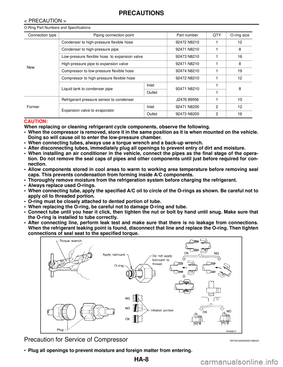
CAUTION:
When replacing or cleaning refrigerant cycle components, observe the following.
When the compressor is removed, store it in the same position as it is when mounted on the vehicle.
Doing so will cause oil to enter the low-pressure chamber.
When connecting tubes, always use a torque wrench and a back-up wrench.
After disconnecting tubes, immediately plug all openings to prevent entry of dirt and moisture.
When installing an air conditioner in the vehicle, connect the pipes as the final stage of the opera-
tion. Do not remove the seal caps of pipes and other components until just before required for con-
nection.
Allow components stored in cool areas to warm to working area temperature before removing seal
caps. This prevents condensation from forming inside A/C components.
Thoroughly remove moisture from the refrigeration system before charging the refrigerant.
Always replace used O-rings.
When connecting tube, apply the specified A/C oil to circle of the O-rings as shown. Be careful not to
apply oil to threaded portion.
O-ring must be closely attached to dented portion of tube.
When replacing the O-ring, be careful not to damage O-ring and tube.
Connect tube until you hear it click, then tighten the nut or bolt by hand until snug. Make sure that
the O-ring is installed to tube correctly.
After connecting line, perform leak test and make sure that there is no leakage from connections.
When the refrigerant leaking point is found, disconnect that line and replace the O-ring. Then tighten
connections of seal seat to the specified torque.
Precaution for Service of CompressorINFOID:0000000001396433
Plug all openings to prevent moisture and foreign matter from entering.
Connection type Piping connection point Part number QTY O-ring size
NewCondenser to high-pressure flexible hose 92472 N8210 1 12
Condenser to high-pressure pipe 92471 N8210 1 8
Low-pressure flexible hose to expansion valve 92473 N8210 1 16
High-pressure pipe to expansion valve 92471 N8210 1 8
Compressor to low-pressure flexible hose 92474 N8210 1 19
Compressor to high-pressure flexible hose 92472 N8210 1 12
Liquid tank to condenser pipeInlet
92471 N82101
8
Outlet 1
FormerRefrigerant pressure sensor to condenser J2476 89956 1 10
Expansion valve to evaporatorInlet 92471 N8200 2 12
Outlet 92473 N8200 2 16
RHA861F
Page 3292 of 5883
HA-10
< PRECAUTION >
PRECAUTIONS
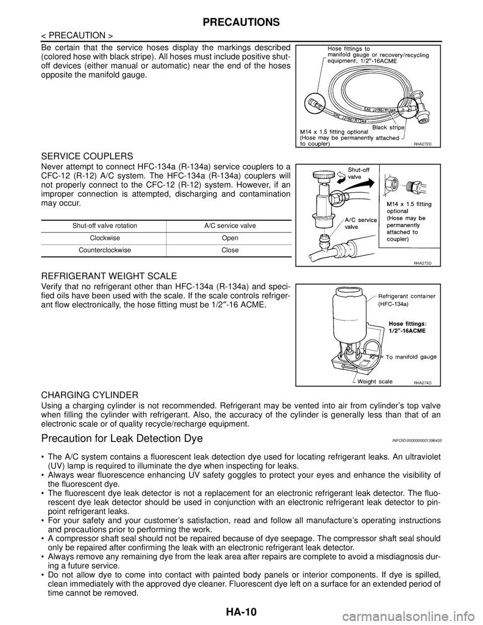
Be certain that the service hoses display the markings described
(colored hose with black stripe). All hoses must include positive shut-
off devices (either manual or automatic) near the end of the hoses
opposite the manifold gauge.
SERVICE COUPLERS
Never attempt to connect HFC-134a (R-134a) service couplers to a
CFC-12 (R-12) A/C system. The HFC-134a (R-134a) couplers will
not properly connect to the CFC-12 (R-12) system. However, if an
improper connection is attempted, discharging and contamination
may occur.
REFRIGERANT WEIGHT SCALE
Verify that no refrigerant other than HFC-134a (R-134a) and speci-
fied oils have been used with the scale. If the scale controls refriger-
ant flow electronically, the hose fitting must be 1/2″-16 ACME.
CHARGING CYLINDER
Using a charging cylinder is not recommended. Refrigerant may be vented into air from cylinder’s top valve
when filling the cylinder with refrigerant. Also, the accuracy of the cylinder is generally less than that of an
electronic scale or of quality recycle/recharge equipment.
Precaution for Leak Detection DyeINFOID:0000000001396435
The A/C system contains a fluorescent leak detection dye used for locating refrigerant leaks. An ultraviolet
(UV) lamp is required to illuminate the dye when inspecting for leaks.
Always wear fluorescence enhancing UV safety goggles to protect your eyes and enhance the visibility of
the fluorescent dye.
The fluorescent dye leak detector is not a replacement for an electronic refrigerant leak detector. The fluo-
rescent dye leak detector should be used in conjunction with an electronic refrigerant leak detector to pin-
point refrigerant leaks.
For your safety and your customer’s satisfaction, read and follow all manufacture’s operating instructions
and precautions prior to performing the work.
A compressor shaft seal should not be repaired because of dye seepage. The compressor shaft seal should
only be repaired after confirming the leak with an electronic refrigerant leak detector.
Always remove any remaining dye from the leak area after repairs are complete to avoid a misdiagnosis dur-
ing a future service.
Do not allow dye to come into contact with painted body panels or interior components. If dye is spilled,
clean immediately with the approved dye cleaner. Fluorescent dye left on a surface for an extended period of
time cannot be removed.
RHA272D
Shut-off valve rotation A/C service valve
Clockwise Open
Counterclockwise Close
RHA273D
RHA274D
Page 3294 of 5883
HA-12
< PREPARATION >
PREPARATION
PREPARATION
PREPARATION
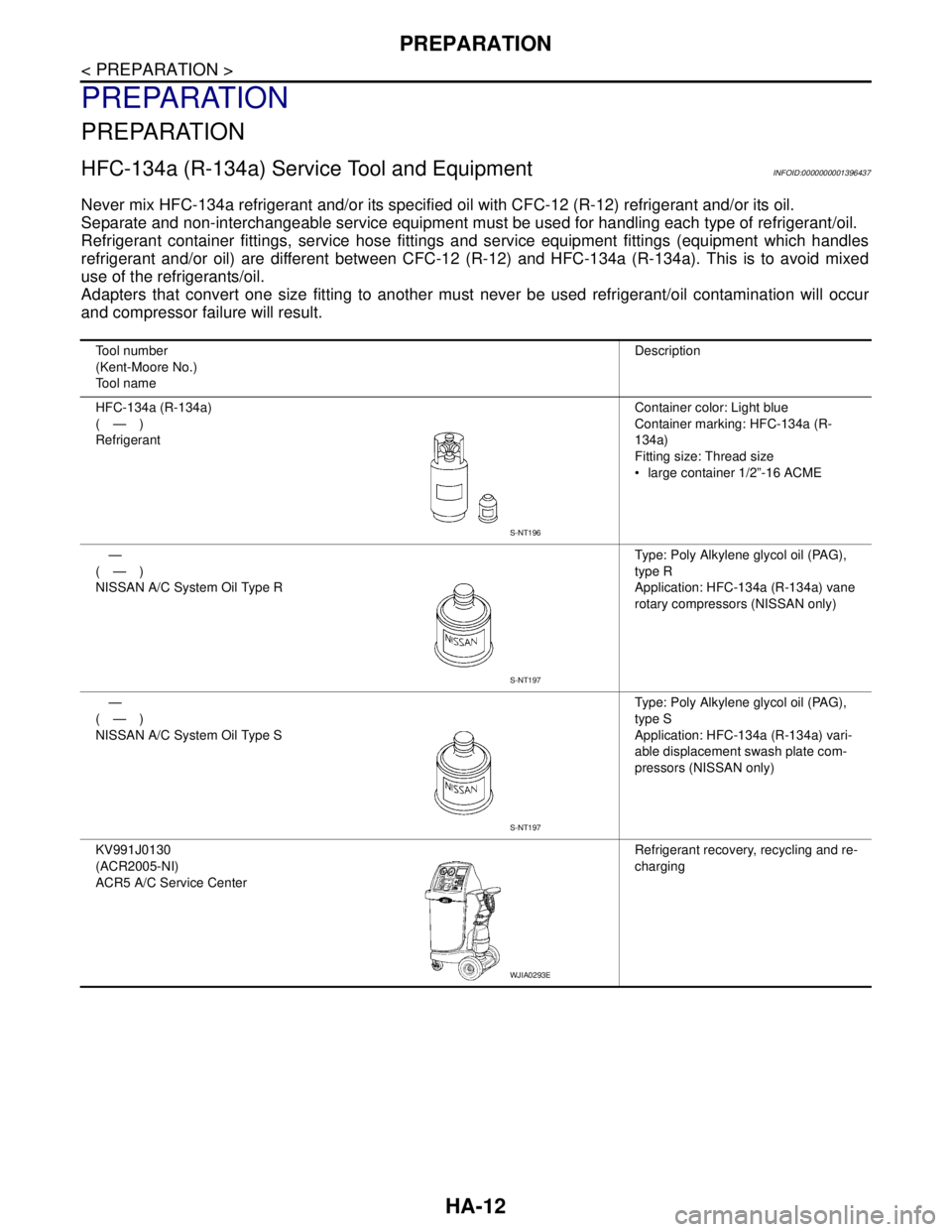
HFC-134a (R-134a) Service Tool and EquipmentINFOID:0000000001396437
Never mix HFC-134a refrigerant and/or its specified oil with CFC-12 (R-12) refrigerant and/or its oil.
Separate and non-interchangeable service equipment must be used for handling each type of refrigerant/oil.
Refrigerant container fittings, service hose fittings and service equipment fittings (equipment which handles
refrigerant and/or oil) are different between CFC-12 (R-12) and HFC-134a (R-134a). This is to avoid mixed
use of the refrigerants/oil.
Adapters that convert one size fitting to another must never be used refrigerant/oil contamination will occur
and compressor failure will result.
Tool number
(Kent-Moore No.)
Tool nameDescription
HFC-134a (R-134a)
(—)
RefrigerantContainer color: Light blue
Container marking: HFC-134a (R-
134a)
Fitting size: Thread size
large container 1/2”-16 ACME
—
(—)
NISSAN A/C System Oil Type RType: Poly Alkylene glycol oil (PAG),
type R
Application: HFC-134a (R-134a) vane
rotary compressors (NISSAN only)
—
(—)
NISSAN A/C System Oil Type SType: Poly Alkylene glycol oil (PAG),
type S
Application: HFC-134a (R-134a) vari-
able displacement swash plate com-
pressors (NISSAN only)
KV991J0130
(ACR2005-NI)
ACR5 A/C Service CenterRefrigerant recovery, recycling and re-
charging
S-NT196
S-NT197
S-NT197
WJIA0293E
Page 3295 of 5883
PREPARATION
HA-13
< PREPARATION >
C
D
E
F
G
H
J
K
L
MA
B
HA
N
O
P
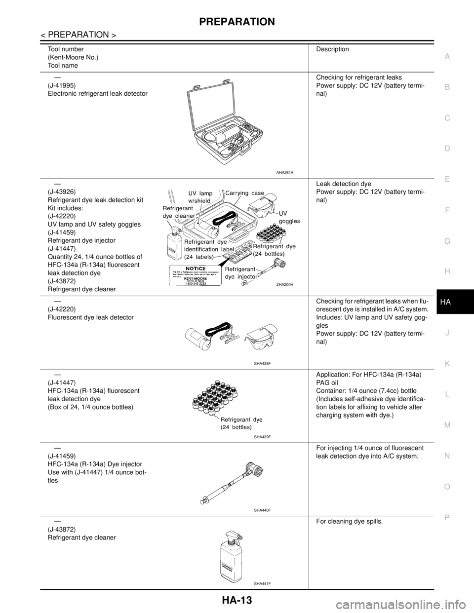
—
(J-41995)
Electronic refrigerant leak detectorChecking for refrigerant leaks
Power supply: DC 12V (battery termi-
nal)
—
(J-43926)
Refrigerant dye leak detection kit
Kit includes:
(J-42220)
UV lamp and UV safety goggles
(J-41459)
Refrigerant dye injector
(J-41447)
Quantity 24, 1/4 ounce bottles of
HFC-134a (R-134a) fluorescent
leak detection dye
(J-43872)
Refrigerant dye cleanerLeak detection dye
Power supply: DC 12V (battery termi-
nal)
—
(J-42220)
Fluorescent dye leak detectorChecking for refrigerant leaks when flu-
orescent dye is installed in A/C system.
Includes: UV lamp and UV safety gog-
gles
Power supply: DC 12V (battery termi-
nal)
—
(J-41447)
HFC-134a (R-134a) fluorescent
leak detection dye
(Box of 24, 1/4 ounce bottles)Application: For HFC-134a (R-134a)
PA G o i l
Container: 1/4 ounce (7.4cc) bottle
(Includes self-adhesive dye identifica-
tion labels for affixing to vehicle after
charging system with dye.)
—
(J-41459)
HFC-134a (R-134a) Dye injector
Use with (J-41447) 1/4 ounce bot-
tlesFor injecting 1/4 ounce of fluorescent
leak detection dye into A/C system.
—
(J-43872)
Refrigerant dye cleanerFor cleaning dye spills. Tool number
(Kent-Moore No.)
Tool nameDescription
AHA281A
ZHA200H
SHA438F
SHA439F
SHA440F
SHA441F
Page 3302 of 5883
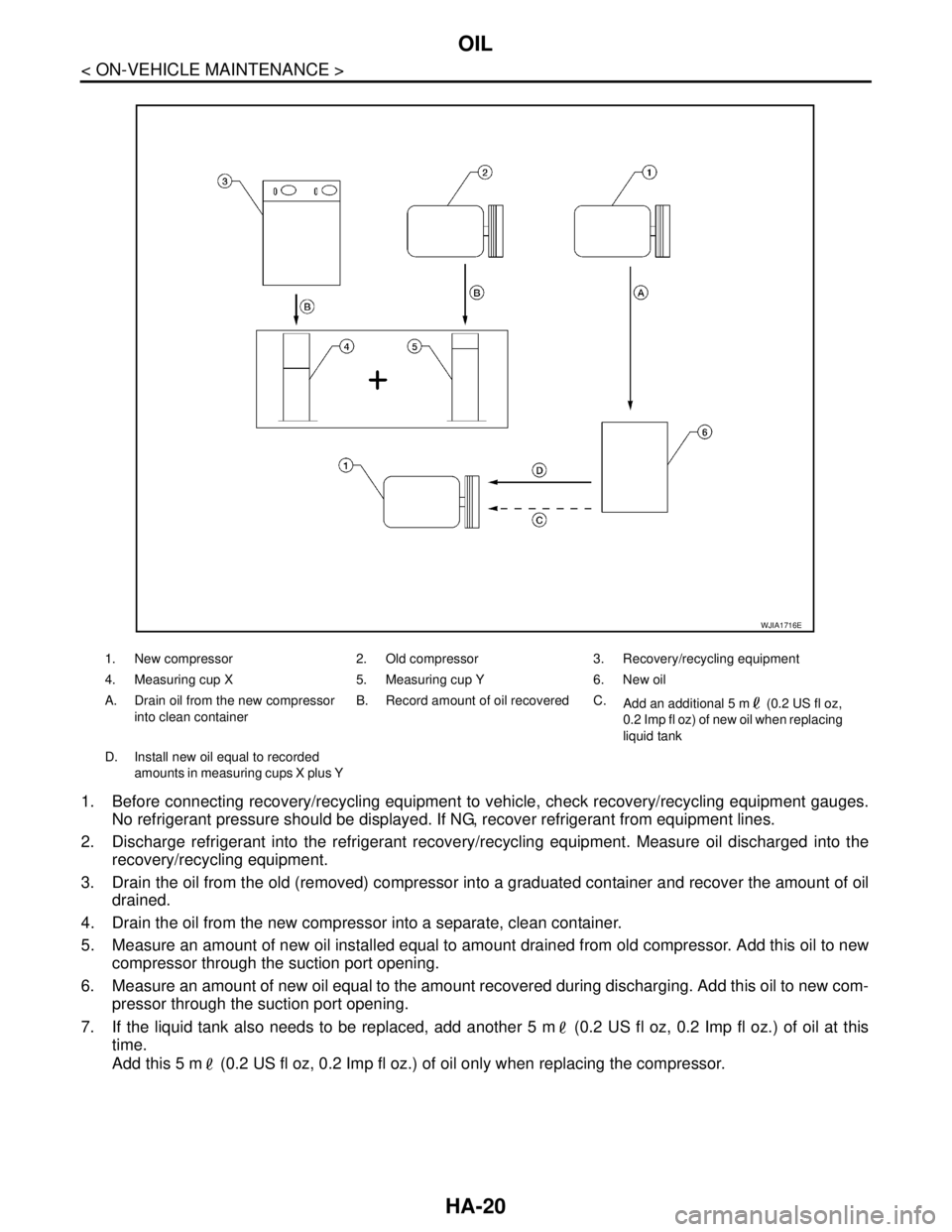
HA-20
< ON-VEHICLE MAINTENANCE >
OIL
1. Before connecting recovery/recycling equipment to vehicle, check recovery/recycling equipment gauges.
No refrigerant pressure should be displayed. If NG, recover refrigerant from equipment lines.
2. Discharge refrigerant into the refrigerant recovery/recycling equipment. Measure oil discharged into the
recovery/recycling equipment.
3. Drain the oil from the old (removed) compressor into a graduated container and recover the amount of oil
drained.
4. Drain the oil from the new compressor into a separate, clean container.
5. Measure an amount of new oil installed equal to amount drained from old compressor. Add this oil to new
compressor through the suction port opening.
6. Measure an amount of new oil equal to the amount recovered during discharging. Add this oil to new com-
pressor through the suction port opening.
7. If the liquid tank also needs to be replaced, add another 5 m (0.2 US fl oz, 0.2 Imp fl oz.) of oil at this
time.
Add this 5 m (0.2 US fl oz, 0.2 Imp fl oz.) of oil only when replacing the compressor.
1. New compressor 2. Old compressor 3. Recovery/recycling equipment
4. Measuring cup X 5. Measuring cup Y 6. New oil
A. Drain oil from the new compressor
into clean containerB. Record amount of oil recovered C.
Add an additional 5 m (0.2 US fl oz,
0.2 Imp fl oz) of new oil when replacing
liquid tank
D. Install new oil equal to recorded
amounts in measuring cups X plus Y
WJIA1716E