fuel tank removal NISSAN TIIDA 2007 Service Repair Manual
[x] Cancel search | Manufacturer: NISSAN, Model Year: 2007, Model line: TIIDA, Model: NISSAN TIIDA 2007Pages: 5883, PDF Size: 78.95 MB
Page 2737 of 5883
![NISSAN TIIDA 2007 Service Repair Manual EM-90
< REMOVAL AND INSTALLATION >[HR16DE]
ENGINE ASSEMBLY
If items or work required are not covered by the engine section, follow the procedures in the applica-
ble sections.
Always use the suppo NISSAN TIIDA 2007 Service Repair Manual EM-90
< REMOVAL AND INSTALLATION >[HR16DE]
ENGINE ASSEMBLY
If items or work required are not covered by the engine section, follow the procedures in the applica-
ble sections.
Always use the suppo](/img/5/57395/w960_57395-2736.png)
EM-90
< REMOVAL AND INSTALLATION >[HR16DE]
ENGINE ASSEMBLY
If items or work required are not covered by the engine section, follow the procedures in the applica-
ble sections.
Always use the support point specified for lifting.
Use either 2-pole lift type or separate type lift as best you can. If board-on type is used for unavoid-
able reasons, support at the rear axle jacking point with a transmission jack or similar tool before
starting work, in preparation for the backward shift of center of gravity.
For supporting points for lifting and jacking point at rear axle, refer to GI-48, "
Garage Jack and
Safety Stand and 2-Pole Lift".
REMOVAL
Outline
Remove the engine and the transaxle assembly from the vehicle downward. Separate the engine and the tran-
saxle.
Preparation
1. Remove the hood assembly. Refer to DLK-214, "Removal and Installation".
2. Remove the cowl top cover and cowl top extension assembly. Refer to EXT-20, "
Removal and Installa-
tion".
3. Release fuel pressure. Refer to EC-377, "
Inspection" (EURO-OBD), EC-681, "Inspection" (WITHOUT
EURO-OBD).
4. Drain engine coolant from radiator. Refer to CO-11, "
Changing Engine Coolant".
CAUTION:
Perform this step when the engine is cold.
Never spill engine coolant on drive belt.
5. Drain the transmission fluid. Refer to TM-628, "
Draining" (M/T models), TM-171, "Changing A/T Fluid" (A/
T models).
6. Remove the following parts.
Engine undercover
Front road wheels and tires: Refer to WT-6, "
Rotation".
Front fender protector (RH and LH): Refer to EXT-22, "
Removal and Installation".
Battery and battery tray: Refer to PG-6, "
Removal and Installation".
Drive belt: Refer to EM-16, "
Removal and Installation".
Air duct and air cleaner case assembly: Refer to EM-27, "
Exploded View".
Radiator hose (upper and lower): Refer to CO-16, "
Component".
Disconnect cooling fan controller wiring harness.
Remove coolant reservoir tank.
Remove fan shroud and cooling fan assembly. Refer to CO-16, "
Component".
Engine Room LH
1. Disconnect all connections of engine harness around the engine mounting insulator (LH), and then tem-
porarily secure the engine harness into the engine side.
CAUTION:
Protect connectors using a resin bag against foreign materials.
2. Remove ground cable at transaxle side.
3. Disconnect fuel feed hose at engine side. Refer to EM-35, "
Exploded View".
4. Disconnect EVAP purge hose and brake booster vacuum hose.
5. Disconnect heater hoses, and install plugs them to prevent engine coolant from draining. Refer to CO-24,
"Exploded View".
6. Disconnect control linkage from transaxle. Refer to TM-189, "
Exploded View" (A/T), TM-630, "Exploded
View" (M/T).
7. Disconnect the clutch tube at transmission side. Refer to CL-12, "
Removal and Installation".
Engine Room RH
1. Remove ground cable between front cover and vehicle.
2. Remove generator and generator bracket; Refer to CHG-15, "
Removal and Installation".
3. Remove A/C compressor with piping connected from the engine. Temporarily secure it on the vehicle side
with a rope to avoid putting load on it. (with A/C models) Refer to HA-34, "
Removal and Installation of
Compressor - HR16DE".
Page 2950 of 5883
![NISSAN TIIDA 2007 Service Repair Manual ENGINE ASSEMBLY
EM-303
< REMOVAL AND INSTALLATION >[K9K]
C
D
E
F
G
H
I
J
K
L
MA
EM
N
P O
Remove engine and transaxle assembly from vehicle down ward. Separate engine and transaxle.
Preparation
Remove NISSAN TIIDA 2007 Service Repair Manual ENGINE ASSEMBLY
EM-303
< REMOVAL AND INSTALLATION >[K9K]
C
D
E
F
G
H
I
J
K
L
MA
EM
N
P O
Remove engine and transaxle assembly from vehicle down ward. Separate engine and transaxle.
Preparation
Remove](/img/5/57395/w960_57395-2949.png)
ENGINE ASSEMBLY
EM-303
< REMOVAL AND INSTALLATION >[K9K]
C
D
E
F
G
H
I
J
K
L
MA
EM
N
P O
Remove engine and transaxle assembly from vehicle down ward. Separate engine and transaxle.
Preparation
Remove the following parts.
Battery ground cable.
Engine undercover.
LH and RH front wheels. Refer to WT-6, "
Rotation".
LH and RH fender protectors. Refer to EXT-22, "
Removal and Installation".
Engine Room
1. Drain engine coolant. Refer to CO-58, "Draining".
CAUTION:
Perform when engine is cold.
2. Remove lower radiator hose. Refer to CO-62, "
Exploded View".
3. Drain transaxle fluid. Refer to TM-672, "
Draining".
4. Disconnect clutch tube at clutch housing and drain clutch fluid.
NOTE:
Cover clutch tube ends to prevent contamination.
5. Remove hood. Refer to DLK-214, "
Removal and Installation".
6. Remove cowl top cover and cowl top extension assembly. Refer to EXT-20, "
Removal and Installation".
7. Remove battery and battery trap. Refer to PG-6, "
Removal and Installation".
8. Disconnect engine room harness from the engine side and position aside.
9. Remove the air duct (inlet). Refer to EM-269, "
Exploded View".
10. Remove engine cover.
11. Remove blow-by hose.
12. Remove air cleaner case and air duct (suction). Refer to EM-269, "
Removal and Installation".
13. Remove reservoir tank and hoses. Refer to CO-62, "
Exploded View".
14. Remove charge air cooler hoses and tubes. Refer to EM-270, "
Exploded View".
15. Remove vacuum hose. Refer to EM-280, "
Removal and Installation".
16. Disconnect fuel feed and return hoses, and plug it to prevent fuel from draining.
17. Remove radiator upper hose. Refer to CO-62, "
Exploded View".
18. Disconnect heater hoses.
19. Disconnect transaxle side harness.
20. Disconnect breather hose transaxle side.
21. Disconnect shift cable and select cable. Refer to TM-674, "
Exploded View".
22. Remove cooling fan. Refer to CO-64, "
Removal and Installation".
23. Remove radiator. Refer to CO-62, "
Exploded View".
24. Disconnect all the body-side vacuum hoses and air hoses at engine side.
Vehicle Underbody
1. Remove drive shaft assembly RH and LH. Refer to Removal and Installation.
2. Remove exhaust front tube. Refer to EX-14, "
Component".
3. Remove drive belt. Refer to EM-263, "
Removal and Installation".
4. Remove A/C compressor and position aside.
NOTE:
Secure it to body with a rope to avoid putting load on A/C lines.
5. Remove lower torque rod. Refer to EM-302, "
Exploded View".
Removal
Page 3161 of 5883
FL-1
ENGINE
C
D
E
F
G
H
I
J
K
L
M
SECTION FL
A
FL
N
O
P
CONTENTS
FUEL SYSTEM
PRECAUTION ...............................................2
PRECAUTIONS ...................................................2
Precaution for Supplemental Restraint System
(SRS) "AIR BAG" and "SEAT BELT PRE-TEN-
SIONER" ...................................................................
2
PREPARATION ............................................3
PREPARATION ...................................................3
Special Service Tool .................................................3
ON-VEHICLE MAINTENANCE .....................4
FUEL SYSTEM ....................................................4
Checking Fuel Line ...................................................4
General Precaution ...................................................4
ON-VEHICLE REPAIR ..................................5
FUEL LEVEL SENSOR UNIT, FUEL FILTER
AND FUEL PUMP ASSEMBLY ..........................
5
HR16DE, HR18DE ...................................................5
Exploded View ..........................................................5
Removal and Installation ..........................................5
K9K ...........................................................................8
Exploded View ..........................................................8
Removal and Installation ..........................................8
FUEL TANK ......................................................10
HR16DE, HR18DE ..................................................10
Exploded View .........................................................10
Removal and Installation .........................................10
K9K ..........................................................................13
Exploded View .........................................................13
Removal and Installation .........................................13
SERVICE DATA AND SPECIFICATIONS
(SDS) ............................................................
16
SERVICE DATA AND SPECIFICATIONS
(SDS) .................................................................
16
Standard and Limit ..................................................16
Page 3165 of 5883
FUEL LEVEL SENSOR UNIT, FUEL FILTER AND FUEL PUMP ASSEMBLY
FL-5
< ON-VEHICLE REPAIR >
C
D
E
F
G
H
I
J
K
L
MA
FL
N
P O
ON-VEHICLE REPAIR
FUEL LEVEL SENSOR UNIT, FUEL FILTER AND FUEL PUMP ASSEMBLY
HR16DE, HR18DEINFOID:0000000001723038
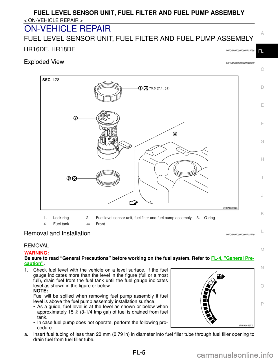
Exploded ViewINFOID:0000000001723039
Removal and InstallationINFOID:0000000001722979
REMOVAL
WARNING:
Be sure to read “General Precautions” before working on the fuel system. Refer to FL-4, "
General Pre-
caution".
1. Check fuel level with the vehicle on a level surface. If the fuel
gauge indicates more than the level in the figure (full or almost
full), drain fuel from the fuel tank until the fuel gauge indicates
level as shown in the figure or below.
NOTE:
Fuel will be spilled when removing fuel pump assembly if fuel
level is above the fuel pump assembly installation surface.
As a guide, fuel level is at the level as shown or below when
approximately 15 (3-1/4 Imp gal) of fuel is drained from fuel
tank.
In case fuel pump does not operate, perform the following pro-
cedure.
a. Insert fuel tubing of less than 20 mm (0.79 in) in diameter into fuel filler tube through fuel filler opening to
drain fuel from fuel filler tube.
1. Lock ring 2. Fuel level sensor unit, fuel filter and fuel pump assembly 3. O-ring
4. Fuel tank⇐Front
JPBIA0300GB
JPBIA0459ZZ
Page 3166 of 5883
FL-6
< ON-VEHICLE REPAIR >
FUEL LEVEL SENSOR UNIT, FUEL FILTER AND FUEL PUMP ASSEMBLY
b. Disconnect fuel filler hose from fuel filler tube. Refer to FL-10, "HR16DE, HR18DE".
c. Insert fuel tubing into fuel tank through fuel filler hose to drain fuel from fuel tank.
2. Release the fuel pressure from the fuel lines. Refer to EC-377, "
Inspection" (HR16DE with EURO-OBD),
EC-681, "
Inspection" (HR16DE without EURO-OBD), EC-1035, "Inspection" (MR18DE).
3. Open fuel filler lid.
4. Open fuel door and unscrew the fuel filler cap to release the pressure inside the fuel tank.
5. Remove rear seat bottom. Refer to SE-18, "
Removal and Installation".
6. Turn the four retainers 90° in a clockwise direction and remove the fuel pump inspection hole cover.
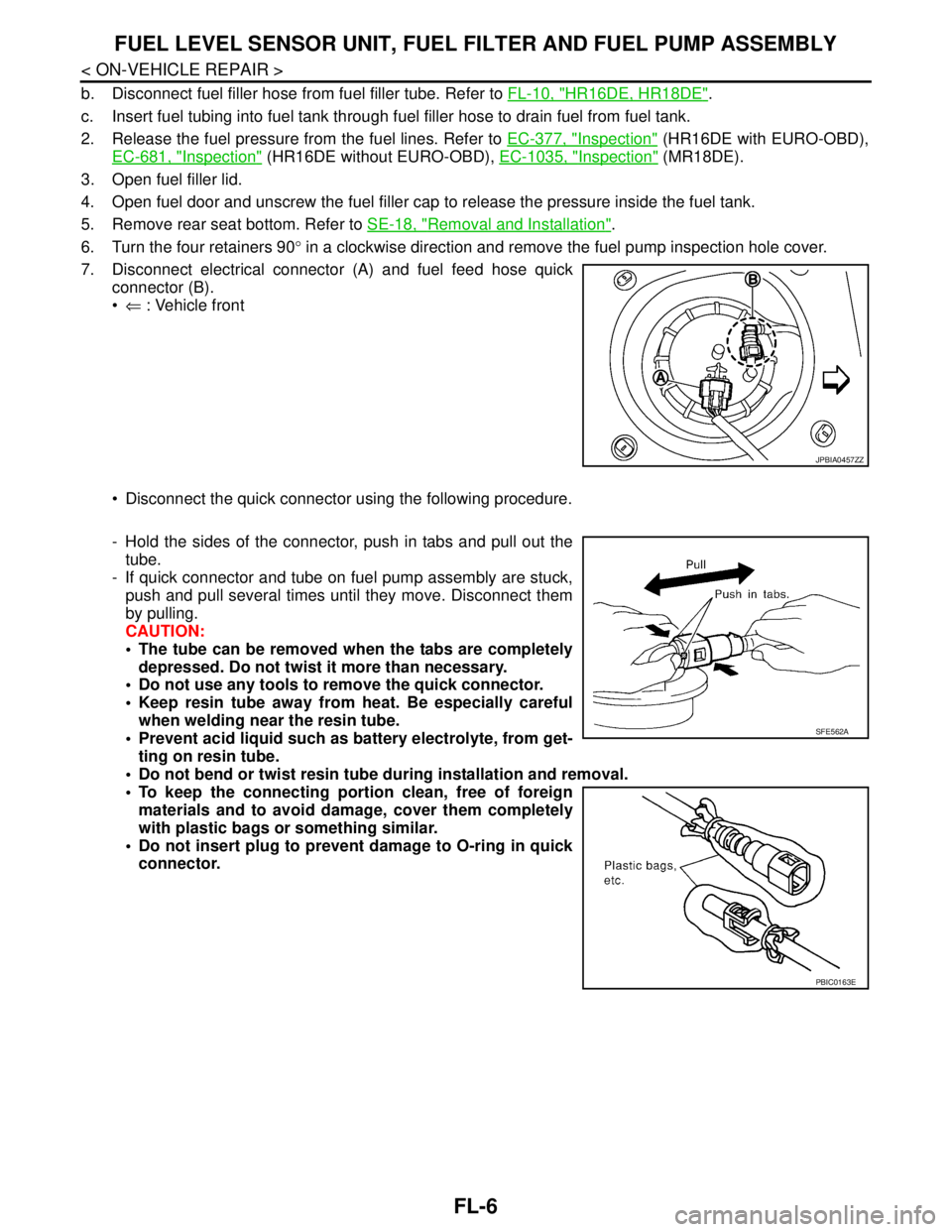
7. Disconnect electrical connector (A) and fuel feed hose quick
connector (B).
⇐ : Vehicle front
Disconnect the quick connector using the following procedure.
- Hold the sides of the connector, push in tabs and pull out the
tube.
- If quick connector and tube on fuel pump assembly are stuck,
push and pull several times until they move. Disconnect them
by pulling.
CAUTION:
The tube can be removed when the tabs are completely
depressed. Do not twist it more than necessary.
Do not use any tools to remove the quick connector.
Keep resin tube away from heat. Be especially careful
when welding near the resin tube.
Prevent acid liquid such as battery electrolyte, from get-
ting on resin tube.
Do not bend or twist resin tube during installation and removal.
To keep the connecting portion clean, free of foreign
materials and to avoid damage, cover them completely
with plastic bags or something similar.
Do not insert plug to prevent damage to O-ring in quick
connector.
JPBIA0457ZZ
SFE562A
PBIC0163E
Page 3167 of 5883
FUEL LEVEL SENSOR UNIT, FUEL FILTER AND FUEL PUMP ASSEMBLY
FL-7
< ON-VEHICLE REPAIR >
C
D
E
F
G
H
I
J
K
L
MA
FL
N
P O
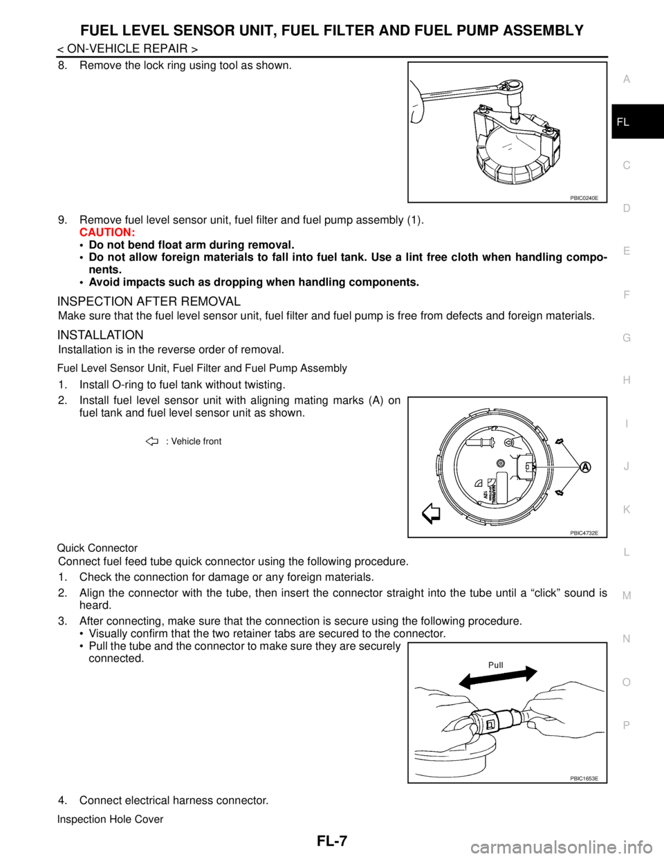
8. Remove the lock ring using tool as shown.
9. Remove fuel level sensor unit, fuel filter and fuel pump assembly (1).
CAUTION:
Do not bend float arm during removal.
Do not allow foreign materials to fall into fuel tank. Use a lint free cloth when handling compo-
nents.
Avoid impacts such as dropping when handling components.
INSPECTION AFTER REMOVAL
Make sure that the fuel level sensor unit, fuel filter and fuel pump is free from defects and foreign materials.
INSTALLATION
Installation is in the reverse order of removal.
Fuel Level Sensor Unit, Fuel Filter and Fuel Pump Assembly
1. Install O-ring to fuel tank without twisting.
2. Install fuel level sensor unit with aligning mating marks (A) on
fuel tank and fuel level sensor unit as shown.
Quick Connector
Connect fuel feed tube quick connector using the following procedure.
1. Check the connection for damage or any foreign materials.
2. Align the connector with the tube, then insert the connector straight into the tube until a “click” sound is
heard.
3. After connecting, make sure that the connection is secure using the following procedure.
Visually confirm that the two retainer tabs are secured to the connector.
Pull the tube and the connector to make sure they are securely
connected.
4. Connect electrical harness connector.
Inspection Hole Cover
PBIC0240E
: Vehicle front
PBIC4732E
PBIC1653E
Page 3168 of 5883
FL-8
< ON-VEHICLE REPAIR >
FUEL LEVEL SENSOR UNIT, FUEL FILTER AND FUEL PUMP ASSEMBLY
Before installing inspection hole cover, confirm that there are no fuel leaks. Refer to "INSPECTION AFTER
INSTALLATION".
1. Install inspection hole cover with the front mark (arrow) facing front of vehicle.
2. Lock clips by turning counterclockwise.
K9KINFOID:0000000001723040
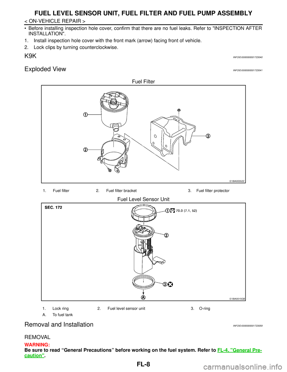
Exploded ViewINFOID:0000000001723041
Fuel Filter
Fuel Level Sensor Unit
Removal and InstallationINFOID:0000000001723059
REMOVAL
WARNING:
Be sure to read “General Precautions” before working on the fuel system. Refer to FL-4, "
General Pre-
caution".
E1BIA0030ZZ
1. Fuel filter 2. Fuel filter bracket 3. Fuel filter protector
E1BIA0015GB
1. Lock ring 2. Fuel level sensor unit 3. O-ring
A. To fuel tank
Page 3169 of 5883
FUEL LEVEL SENSOR UNIT, FUEL FILTER AND FUEL PUMP ASSEMBLY
FL-9
< ON-VEHICLE REPAIR >
C
D
E
F
G
H
I
J
K
L
MA
FL
N
P O
1. Disconnect battery ground cable.
2. Open fuel filler lid and filler cap to release the pressure inside the fuel tank.
3. Remove rear seat cushion. Refer to SE-18, "
Removal and Installation".
4. Remove the fuel pump inspection hole cover.
5. Disconnect electrical connector.
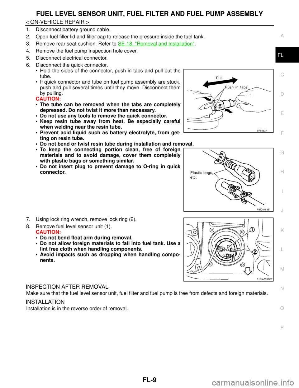
6. Disconnect the quick connector.
Hold the sides of the connector, push in tabs and pull out the
tube.
If quick connector and tube on fuel pump assembly are stuck,
push and pull several times until they move. Disconnect them
by pulling.
CAUTION:
The tube can be removed when the tabs are completely
depressed. Do not twist it more than necessary.
Do not use any tools to remove the quick connector.
Keep resin tube away from heat. Be especially careful
when welding near the resin tube.
Prevent acid liquid such as battery electrolyte, from get-
ting on resin tube.
Do not bend or twist resin tube during installation and removal.
To keep the connecting portion clean, free of foreign
materials and to avoid damage, cover them completely
with plastic bags or something similar.
Do not insert plug to prevent damage to O-ring in quick
connector.
7. Using lock ring wrench, remove lock ring (2).
8. Remove fuel level sensor unit (1).
CAUTION:
Do not bend float arm during removal.
Do not allow foreign materials to fall into fuel tank. Use a
lint free cloth when handling components.
Avoid impacts such as dropping when handling compo-
nents.
INSPECTION AFTER REMOVAL
Make sure that the fuel level sensor unit, fuel filter and fuel pump is free from defects and foreign materials.
INSTALLATION
Installation is in the reverse order of removal.
SFE562A
PBIC0163E
E1BIA0033ZZ
Page 3170 of 5883
FL-10
< ON-VEHICLE REPAIR >
FUEL TANK
FUEL TANK
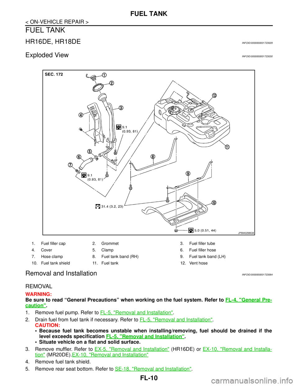
HR16DE, HR18DEINFOID:0000000001723029
Exploded ViewINFOID:0000000001723030
Removal and InstallationINFOID:0000000001723064
REMOVAL
WARNING:
Be sure to read “General Precautions” when working on the fuel system. Refer to FL-4, "
General Pre-
caution".
1. Remove fuel pump. Refer to FL-5, "
Removal and Installation".
2. Drain fuel from fuel tank if necessary. Refer to FL-5, "
Removal and Installation".
CAUTION:
Because fuel tank becomes unstable when installing/removing, fuel should be drained if the
level exceeds specification FL-5, "
Removal and Installation".
Situate vehicle on a flat and solid surface.
3. Remove muffler. Refer to EX-5, "
Removal and Installation" (HR16DE) or EX-10, "Removal and Installa-
tion" (MR20DE).EX-10, "Removal and Installation"
4. Remove fuel tank shield.
5. Remove rear seat bottom. Refer to SE-18, "
Removal and Installation".
1. Fuel filler cap 2. Grommet 3. Fuel filler tube
4. Cover 5. Clamp 6. Fuel filler hose
7. Hose clamp 8. Fuel tank band (RH) 9. Fuel tank band (LH)
10. Fuel tank shield 11. Fuel tank 12. Vent hose
JPBIA0298GB
Page 3171 of 5883
FUEL TANK
FL-11
< ON-VEHICLE REPAIR >
C
D
E
F
G
H
I
J
K
L
MA
FL
N
P O
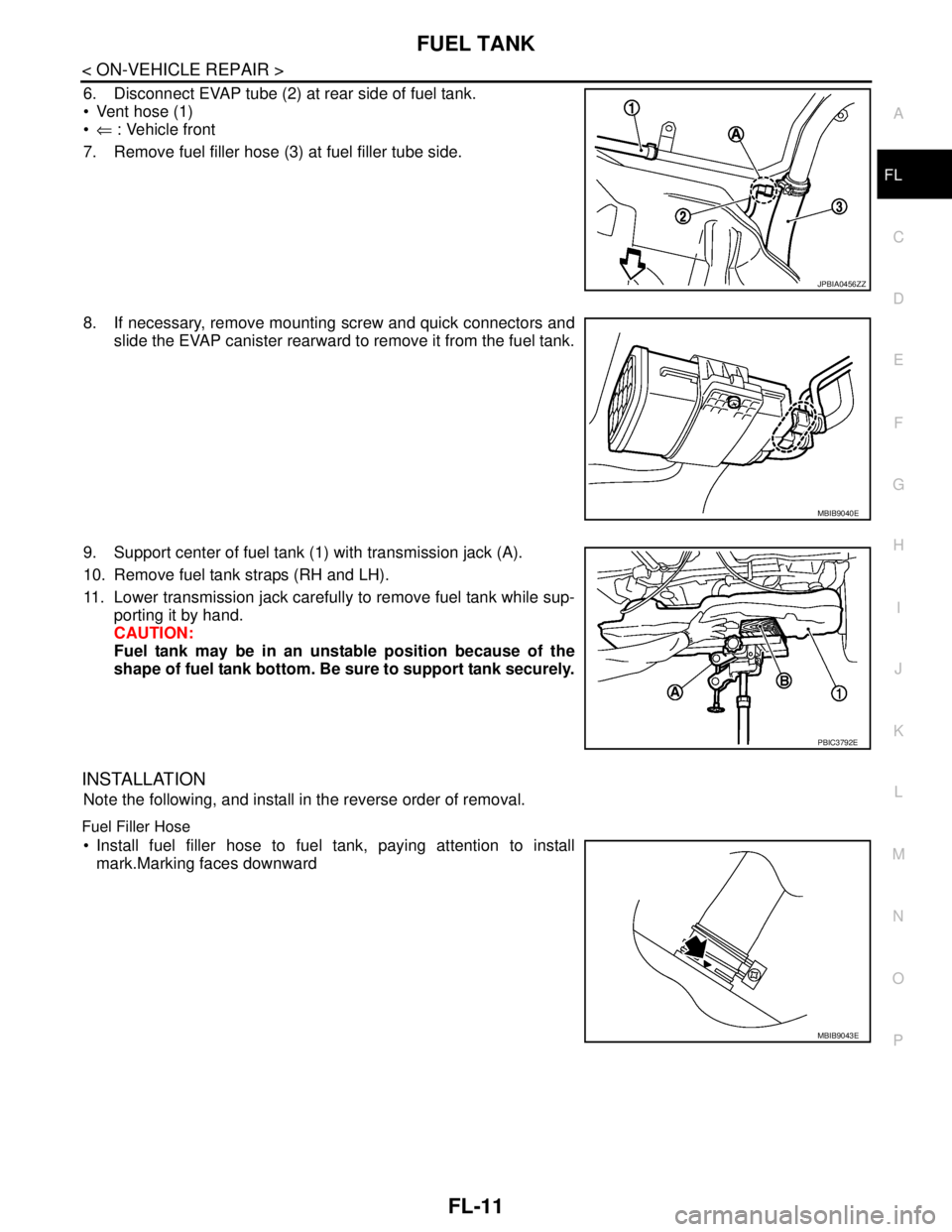
6. Disconnect EVAP tube (2) at rear side of fuel tank.
Vent hose (1)
⇐ : Vehicle front
7. Remove fuel filler hose (3) at fuel filler tube side.
8. If necessary, remove mounting screw and quick connectors and
slide the EVAP canister rearward to remove it from the fuel tank.
9. Support center of fuel tank (1) with transmission jack (A).
10. Remove fuel tank straps (RH and LH).
11. Lower transmission jack carefully to remove fuel tank while sup-
porting it by hand.
CAUTION:
Fuel tank may be in an unstable position because of the
shape of fuel tank bottom. Be sure to support tank securely.
INSTALLATION
Note the following, and install in the reverse order of removal.
Fuel Filler Hose
Install fuel filler hose to fuel tank, paying attention to install
mark.Marking faces downward
JPBIA0456ZZ
MBIB9040E
PBIC3792E
MBIB9043E