maintenance NISSAN TIIDA 2007 Service Repair Manual
[x] Cancel search | Manufacturer: NISSAN, Model Year: 2007, Model line: TIIDA, Model: NISSAN TIIDA 2007Pages: 5883, PDF Size: 78.95 MB
Page 1 of 5883

MODEL C11 SERIES
2007 NISSAN EUROPE S.A.S.
All rights reserved. No part of this Electronic Service Manual may be reproduced or stored in a retrieval system, or transmitted in any form,
or by any means, electronic, mechanical, photocopying, recording or otherwise, without the prior written permission of Nissan Europe
S.A.S., Paris, France.
A GENERAL INFORMATION
B ENGINE
D TRANSMISSION& DRIVELINE
E SUSPENSION F BRAKES
G STEERING H RESTRAINTS
I VENTILATION, HEATER & AIR CONDITIONER
J BODY INTERIOR
K BODY EXTERIOR, DOOR, ROOF & VEHICLE SECURITY
L DRIVER CONTROLS
M ELECTRICAL & POWER CONTROL
N DRIVER INFORMATION & MULTIMEDIA
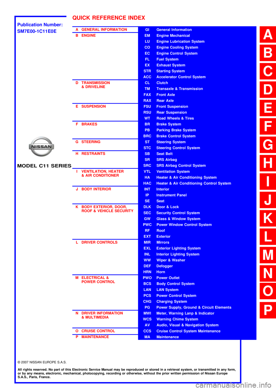
O CRUISE CONTROL P MAINTENANCEGI General Information
EM Engine Mechanical
LU Engine Lubrication System
CO Engine Cooling System
EC Engine Control System
FL Fuel System
EX Exhaust System
STR Starting System
ACC Accelerator Control System
CL Clutch
TM Transaxle & Transmission
FAX Front Axle
RAX Rear Axle
FSU Front Suspension
RSU Rear Suspension
WT Road Wheels & Tires
BR Brake System
PB Parking Brake System
BRC Brake Control System
ST Steering System
STC Steering Control System
SB Seat Belt
SR SRS Airbag
SRC SRS Airbag Control System
VTL Ventilation System
HA Heater & Air Conditioning System
HAC Heater & Air Conditioning Control System
INT Interior
IP Instrument Panel
SE Seat
DLK Door & Lock
SEC Security Control System
GW Glass & Window System
PWC Power Window Control System
RF Roof
EXT Exterior
MIR Mirrors
EXL Exterior Lighting System
INL Interior Lighting System
WW Wiper & Washer
DEF Defogger
HRN Horn
PWO Power Outlet
BCS Body Control System
LAN LAN System
PCS Power Control System
CHG Charging System
PG Power Supply, Ground & Circuit Elements
MWI Meter, Warning Lanp & Indicator
WCS Warning Chime System
AV Audio, Visual & Navigation System
CCS Cruise Control System Maintenance
MA Maintenance
QUICK REFERENCE INDEX
A
B
C
D
E
F
G
H
I
J
K
L
M
N
O
P
M
Publication Number:
SM7E00-1C11E0E
Page 2 of 5883

FOREWORD
This manual contains maintenance and repair procedures for the NISSAN
TIIDA, model C11 series.
In order to assure your safety and the efficient functioning of the vehicle,
this manual should be read thoroughly. It is especially important that the
PRECAUTIONS in the GI section be completely understood before starting
any repair task.
All information in this manual is based on the latest product information
at the time of publication. The right is reserved to make changes in speci-
fications and methods at any time without notice.
IMPORTANT SAFETY NOTICE
The proper performance of service is essential for both the safety of the
technician and the efficient functioning of the vehicle.
The service methods in this Service Manual are described in such a man-
ner that the service may be performed safely and accurately.
Service varies with the procedures used, the skills of the technician and the
tools and parts available. Accordingly, anyone using service procedures,
tools or parts which are not specifically recommended by NISSAN must
first be completely satisfied that neither personal safety nor the vehicle's
safety will be jeopardized by the service method selected.
NISSAN EUROPE S.A.S.
Service Engineering SectionParis, France
Page 4 of 5883

ACC-2
< PRECAUTION >
PRECAUTIONS
PRECAUTION
PRECAUTIONS
Precaution for Supplemental Restraint System (SRS) "AIR BAG" and "SEAT BELT
PRE-TENSIONER"
INFOID:0000000001724596
The Supplemental Restraint System such as “AIR BAG” and “SEAT BELT PRE-TENSIONER”, used along
with a front seat belt, helps to reduce the risk or severity of injury to the driver and front passenger for certain
types of collision. Information necessary to service the system safely is included in the SR and SB section of
this Service Manual.
WARNING:
• To avoid rendering the SRS inoperative, which could increase the risk of personal injury or death in
the event of a collision which would result in air bag inflation, all maintenance must be performed by
an authorized NISSAN/INFINITI dealer.
Improper maintenance, including incorrect removal and installation of the SRS, can lead to personal
injury caused by unintentional activation of the system. For removal of Spiral Cable and Air Bag
Module, see the SR section.
Do not use electrical test equipment on any circuit related to the SRS unless instructed to in this
Service Manual. SRS wiring harnesses can be identified by yellow and/or orange harnesses or har-
ness connectors.
Page 26 of 5883
![NISSAN TIIDA 2007 Service Repair Manual AV
PRECAUTIONS
AV-21
< PRECAUTION >[AUDIO WITHOUT NAVIGATION]
C
D
E
F
G
H
I
J
K
L
MB A
O
P
PRECAUTION
PRECAUTIONS
Precaution for Supplemental Restraint System (SRS) "AIR BAG" and "SEAT BELT
PRE-TENSI NISSAN TIIDA 2007 Service Repair Manual AV
PRECAUTIONS
AV-21
< PRECAUTION >[AUDIO WITHOUT NAVIGATION]
C
D
E
F
G
H
I
J
K
L
MB A
O
P
PRECAUTION
PRECAUTIONS
Precaution for Supplemental Restraint System (SRS) "AIR BAG" and "SEAT BELT
PRE-TENSI](/img/5/57395/w960_57395-25.png)
AV
PRECAUTIONS
AV-21
< PRECAUTION >[AUDIO WITHOUT NAVIGATION]
C
D
E
F
G
H
I
J
K
L
MB A
O
P
PRECAUTION
PRECAUTIONS
Precaution for Supplemental Restraint System (SRS) "AIR BAG" and "SEAT BELT
PRE-TENSIONER"
INFOID:0000000001731028
The Supplemental Restraint System such as “AIR BAG” and “SEAT BELT PRE-TENSIONER”, used along
with a front seat belt, helps to reduce the risk or severity of injury to the driver and front passenger for certain
types of collision. Information necessary to service the system safely is included in the “SRS AIRBAG” and
“SEAT BELT” of this Service Manual.
WARNING:
• To avoid rendering the SRS inoperative, which could increase the risk of personal injury or death in
the event of a collision which would result in air bag inflation, all maintenance must be performed by
an authorized NISSAN/INFINITI dealer.
Improper maintenance, including incorrect removal and installation of the SRS, can lead to personal
injury caused by unintentional activation of the system. For removal of Spiral Cable and Air Bag
Module, see the “SRS AIRBAG”.
Do not use electrical test equipment on any circuit related to the SRS unless instructed to in this
Service Manual. SRS wiring harnesses can be identified by yellow and/or orange harnesses or har-
ness connectors.
Page 37 of 5883
![NISSAN TIIDA 2007 Service Repair Manual AV-32
< FUNCTION DIAGNOSIS >[AUDIO WITH NAVIGATION]
MULTI AV SYSTEM
FUNCTION DIAGNOSIS
MULTI AV SYSTEM
System DiagramINFOID:0000000001728627
System DescriptionINFOID:0000000001728628
Multi AV system m NISSAN TIIDA 2007 Service Repair Manual AV-32
< FUNCTION DIAGNOSIS >[AUDIO WITH NAVIGATION]
MULTI AV SYSTEM
FUNCTION DIAGNOSIS
MULTI AV SYSTEM
System DiagramINFOID:0000000001728627
System DescriptionINFOID:0000000001728628
Multi AV system m](/img/5/57395/w960_57395-36.png)
AV-32
< FUNCTION DIAGNOSIS >[AUDIO WITH NAVIGATION]
MULTI AV SYSTEM
FUNCTION DIAGNOSIS
MULTI AV SYSTEM
System DiagramINFOID:0000000001728627
System DescriptionINFOID:0000000001728628
Multi AV system means that the following systems are integrated.
Two AV communication lines (H, L) connect between units that configure MULTI AV system. NAVI control
unit controls by sending/receiving data one by one with each unit (slave unit) that configures them com-
pletely as a master unit.
Two AV communication lines (H, L) adopt a twisted pair line that is resistant to noise.
NAVI control unit is connected by CAN communication, and it receives data signal from ECM, combination
meter. It computes and displays fuel economy information value with the obtained information. Sending/
receiving of data signal is performed by BCM. Also, it sends the required signal of vehicle setting and
receives the response signal.
ALNIA0882GB
System name System explanation
NAVIGATION SYSTEMAV- 3 5 , "
System Description"
AUDIO SYSTEMXX-XX, "*****"
VEHICLE INFORMATION SYSTEM Status of audio, fuel economy, maintenance and navigation is
displayed.
NAVI control unit displays the fuel consumption status and trip
computer status while receiving data signal through CAN com-
munication from ECM, combination meter and BCM.
HANDS-FREE PHONE SYSTEM Refer to the following “HANDS-FREE PHONE SYSTEM”.
Page 124 of 5883
![NISSAN TIIDA 2007 Service Repair Manual AV
PRECAUTIONS
AV-119
< PRECAUTION >[AUDIO WITH NAVIGATION]
C
D
E
F
G
H
I
J
K
L
MB A
O
P
PRECAUTION
PRECAUTIONS
Precaution for Supplemental Restraint System (SRS) "AIR BAG" and "SEAT BELT
PRE-TENSION NISSAN TIIDA 2007 Service Repair Manual AV
PRECAUTIONS
AV-119
< PRECAUTION >[AUDIO WITH NAVIGATION]
C
D
E
F
G
H
I
J
K
L
MB A
O
P
PRECAUTION
PRECAUTIONS
Precaution for Supplemental Restraint System (SRS) "AIR BAG" and "SEAT BELT
PRE-TENSION](/img/5/57395/w960_57395-123.png)
AV
PRECAUTIONS
AV-119
< PRECAUTION >[AUDIO WITH NAVIGATION]
C
D
E
F
G
H
I
J
K
L
MB A
O
P
PRECAUTION
PRECAUTIONS
Precaution for Supplemental Restraint System (SRS) "AIR BAG" and "SEAT BELT
PRE-TENSIONER"
INFOID:0000000001731029
The Supplemental Restraint System such as “AIR BAG” and “SEAT BELT PRE-TENSIONER”, used along
with a front seat belt, helps to reduce the risk or severity of injury to the driver and front passenger for certain
types of collision. Information necessary to service the system safely is included in the “SRS AIRBAG” and
“SEAT BELT” of this Service Manual.
WARNING:
To avoid rendering the SRS inoperative, which could increase the risk of personal injury or death in
the event of a collision which would result in air bag inflation, all maintenance must be performed by
an authorized NISSAN/INFINITI dealer.
Improper maintenance, including incorrect removal and installation of the SRS, can lead to personal
injury caused by unintentional activation of the system. For removal of Spiral Cable and Air Bag
Module, see the “SRS AIRBAG”.
Do not use electrical test equipment on any circuit related to the SRS unless instructed to in this
Service Manual. SRS wiring harnesses can be identified by yellow and/or orange harnesses or har-
ness connectors.
Page 191 of 5883

BCS-56
< PRECAUTION >
PRECAUTIONS
PRECAUTION
PRECAUTIONS
Precaution for Supplemental Restraint System (SRS) "AIR BAG" and "SEAT BELT
PRE-TENSIONER"
INFOID:0000000001523305
The Supplemental Restraint System such as “AIR BAG” and “SEAT BELT PRE-TENSIONER”, used along
with a front seat belt, helps to reduce the risk or severity of injury to the driver and front passenger for certain
types of collision. Information necessary to service the system safely is included in the SR and SB section of
this Service Manual.
WARNING:
To avoid rendering the SRS inoperative, which could increase the risk of personal injury or death in
the event of a collision which would result in air bag inflation, all maintenance must be performed by
an authorized NISSAN/INFINITI dealer.
Improper maintenance, including incorrect removal and installation of the SRS, can lead to personal
injury caused by unintentional activation of the system. For removal of Spiral Cable and Air Bag
Module, see the SR section.
Do not use electrical test equipment on any circuit related to the SRS unless instructed to in this
Service Manual. SRS wiring harnesses can be identified by yellow and/or orange harnesses or har-
ness connectors.
Page 193 of 5883

BR-1
BRAKES
C
D
E
G
H
I
J
K
L
M
SECTION BR
A
B
BR
N
O
P
CONTENTS
BRAKE SYSTEM
PRECAUTION ...............................................3
PRECAUTIONS ...................................................3
Precaution for Supplemental Restraint System
(SRS) "AIR BAG" and "SEAT BELT PRE-TEN-
SIONER" ...................................................................
3
Precaution for Brake System ....................................3
PREPARATION ............................................4
PREPARATION ...................................................4
Commercial Service Tool ..........................................4
SYMPTOM DIAGNOSIS ...............................5
NOISE, VIBRATION AND HARSHNESS
(NVH) TROUBLESHOOTING .............................
5
NVH Troubleshooting Chart ......................................5
ON-VEHICLE MAINTENANCE .....................6
BRAKE PEDAL ...................................................6
Inspection and Adjustment ........................................6
BRAKE FLUID .....................................................8
On Board Inspection .................................................8
Drain and Refill ..........................................................8
Bleeding Brake System .............................................8
FRONT DISC BRAKE ........................................10
Inspection ................................................................10
REAR DISC BRAKE ..........................................11
Inspection ................................................................11
ON-VEHICLE REPAIR .................................12
BRAKE PEDAL ..................................................12
Removal and Installation .........................................12
BRAKE TUBE AND HOSE ................................14
Hydraulic Circuit ......................................................14
Front Brake Tube and Hose ....................................14
Rear Brake Tube and Hose .....................................15
Inspection After Installation .....................................15
DUAL PROPORTIONING VALVE ....................17
Removal and Installation .........................................17
Inspection ................................................................17
BRAKE MASTER CYLINDER ..........................18
On-Board Inspection ................................................18
Removal and Installation .........................................18
BRAKE BOOSTER ...........................................19
On Board Inspection ................................................19
Removal and Installation .........................................19
VACUUM LINES ...............................................22
Component ..............................................................22
Removal and Installation .........................................22
Inspection ................................................................22
FRONT DISC BRAKE .......................................24
Component ..............................................................24
Removal and Installation of Brake Pad ...................24
Removal and Installation of Brake Caliper Assem-
bly ............................................................................
25
Brake Burnishing .....................................................26
REAR DISC BRAKE .........................................27
Component ..............................................................27
Removal and Installation of Brake Pad ...................28
Removal and Installation of Brake Caliper Assem-
bly ............................................................................
28
Brake Burnishing .....................................................29
DISASSEMBLY AND ASSEMBLY ..............30
BRAKE MASTER CYLINDER ..........................30
Disassembly and Assembly .....................................30
FRONT DISC BRAKE .......................................34
Disassembly and Assembly of Brake Caliper As-
sembly .....................................................................
34
Page 195 of 5883

PRECAUTIONS
BR-3
< PRECAUTION >
C
D
E
G
H
I
J
K
L
MA
B
BR
N
O
P
PRECAUTION
PRECAUTIONS
Precaution for Supplemental Restraint System (SRS) "AIR BAG" and "SEAT BELT
PRE-TENSIONER"
INFOID:0000000001716907
The Supplemental Restraint System such as “AIR BAG” and “SEAT BELT PRE-TENSIONER”, used along
with a front seat belt, helps to reduce the risk or severity of injury to the driver and front passenger for certain
types of collision. This system includes seat belt switch inputs and dual stage front air bag modules. The SRS
system uses the seat belt switches to determine the front air bag deployment, and may only deploy one front
air bag, depending on the severity of a collision and whether the front occupants are belted or unbelted.
Information necessary to service the system safely is included in the SR and SB section of this Service Man-
ual.
WARNING:
• To avoid rendering the SRS inoperative, which could increase the risk of personal injury or death in
the event of a collision which would result in air bag inflation, all maintenance must be performed by
an authorized NISSAN/INFINITI dealer.
Improper maintenance, including incorrect removal and installation of the SRS, can lead to personal
injury caused by unintentional activation of the system. For removal of Spiral Cable and Air Bag
Module, see the SR section.
Do not use electrical test equipment on any circuit related to the SRS unless instructed to in this
Service Manual. SRS wiring harnesses can be identified by yellow and/or orange harnesses or har-
ness connectors.
Precaution for Brake SystemINFOID:0000000001716908
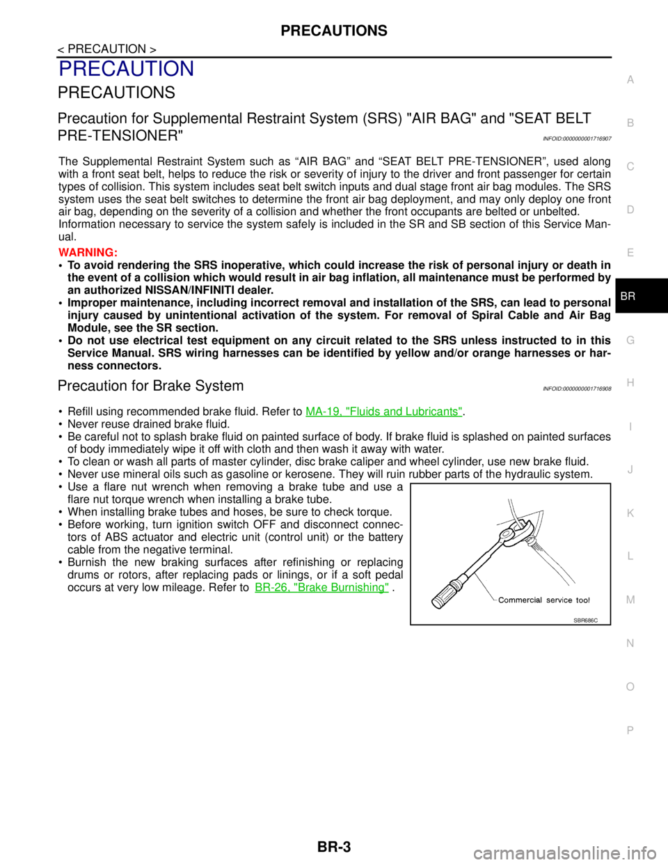
Refill using recommended brake fluid. Refer to MA-19, "Fluids and Lubricants".
Never reuse drained brake fluid.
Be careful not to splash brake fluid on painted surface of body. If brake fluid is splashed on painted surfaces
of body immediately wipe it off with cloth and then wash it away with water.
To clean or wash all parts of master cylinder, disc brake caliper and wheel cylinder, use new brake fluid.
Never use mineral oils such as gasoline or kerosene. They will ruin rubber parts of the hydraulic system.
Use a flare nut wrench when removing a brake tube and use a
flare nut torque wrench when installing a brake tube.
When installing brake tubes and hoses, be sure to check torque.
Before working, turn ignition switch OFF and disconnect connec-
tors of ABS actuator and electric unit (control unit) or the battery
cable from the negative terminal.
Burnish the new braking surfaces after refinishing or replacing
drums or rotors, after replacing pads or linings, or if a soft pedal
occurs at very low mileage. Refer toBR-26, "
Brake Burnishing" .
SBR686C
Page 198 of 5883

BR-6
< ON-VEHICLE MAINTENANCE >
BRAKE PEDAL
ON-VEHICLE MAINTENANCE
BRAKE PEDAL
Inspection and AdjustmentINFOID:0000000001716917
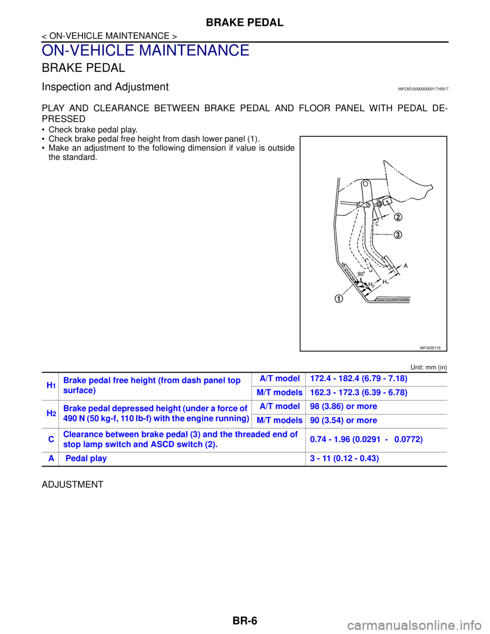
PLAY AND CLEARANCE BETWEEN BRAKE PEDAL AND FLOOR PANEL WITH PEDAL DE-
PRESSED
Check brake pedal play.
Check brake pedal free height from dash lower panel (1).
Make an adjustment to the following dimension if value is outside
the standard.
Unit: mm (in)
ADJUSTMENT
WFIA0511E
H1Brake pedal free height (from dash panel top
surface)A/T model 172.4 - 182.4 (6.79 - 7.18)
M/T models 162.3 - 172.3 (6.39 - 6.78)
H
2Brake pedal depressed height (under a force of
490 N (50 kg-f, 110 lb-f) with the engine running)A/T model 98 (3.86) or more
M/T models 90 (3.54) or more
CClearance between brake pedal (3) and the threaded end of
stop lamp switch and ASCD switch (2).0.74 - 1.96 (0.0291 - 0.0772)
A Pedal play 3 - 11 (0.12 - 0.43)