service interval NISSAN TIIDA 2007 Service Repair Manual
[x] Cancel search | Manufacturer: NISSAN, Model Year: 2007, Model line: TIIDA, Model: NISSAN TIIDA 2007Pages: 5883, PDF Size: 78.95 MB
Page 473 of 5883
CL-8
< SERVICE INFORMATION >
CLUTCH FLUID
CLUTCH FLUID
Air Bleeding ProcedureINFOID:0000000001375295
NOTE:
Do not use a vacuum assist or any other type of power bleeder on this system. Use of a vacuum assist or
power bleeder will not purge all the air from the system.
CAUTION:
Carefully monitor fluid level in reservoir tank during bleeding operation.
Keep painted surface of body and other parts free of clutch fluid. If it spills, wipe up immediately and
wash the affected area with water.
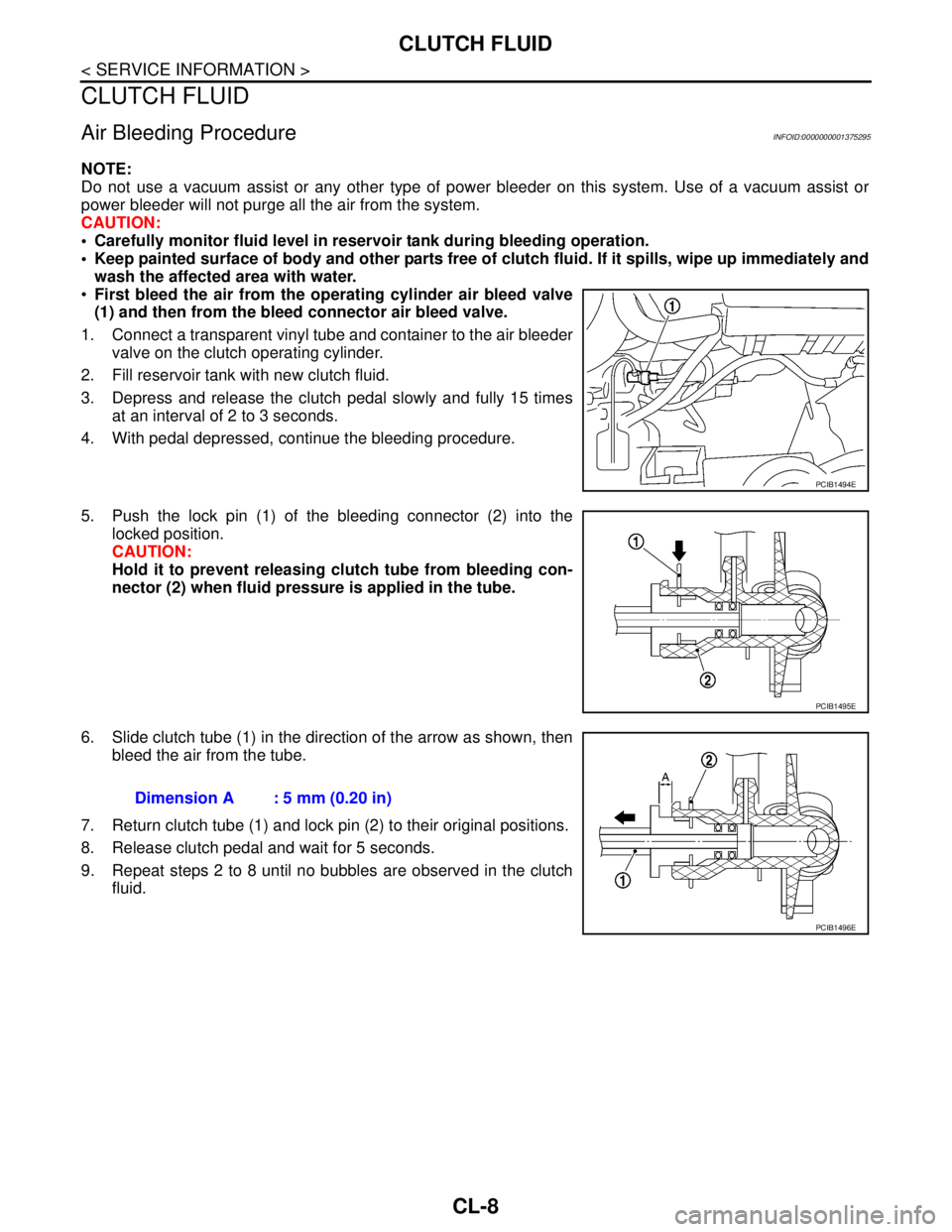
First bleed the air from the operating cylinder air bleed valve
(1) and then from the bleed connector air bleed valve.
1. Connect a transparent vinyl tube and container to the air bleeder
valve on the clutch operating cylinder.
2. Fill reservoir tank with new clutch fluid.
3. Depress and release the clutch pedal slowly and fully 15 times
at an interval of 2 to 3 seconds.
4. With pedal depressed, continue the bleeding procedure.
5. Push the lock pin (1) of the bleeding connector (2) into the
locked position.
CAUTION:
Hold it to prevent releasing clutch tube from bleeding con-
nector (2) when fluid pressure is applied in the tube.
6. Slide clutch tube (1) in the direction of the arrow as shown, then
bleed the air from the tube.
7. Return clutch tube (1) and lock pin (2) to their original positions.
8. Release clutch pedal and wait for 5 seconds.
9. Repeat steps 2 to 8 until no bubbles are observed in the clutch
fluid.
PCIB1494E
PCIB1495E
Dimension A : 5 mm (0.20 in)
PCIB1496E
Page 3496 of 5883
![NISSAN TIIDA 2007 Service Repair Manual POWER SUPPLY AND GROUND CIRCUIT FOR CONTROLLER
HAC-163
< COMPONENT DIAGNOSIS >[AUTO AIR CONDITIONER (W/O NAVI)]
C
D
E
F
G
H
J
K
L
MA
B
HAC
N
O
P
POWER SUPPLY AND GROUND CIRCUIT FOR CONTROLLER
Componen NISSAN TIIDA 2007 Service Repair Manual POWER SUPPLY AND GROUND CIRCUIT FOR CONTROLLER
HAC-163
< COMPONENT DIAGNOSIS >[AUTO AIR CONDITIONER (W/O NAVI)]
C
D
E
F
G
H
J
K
L
MA
B
HAC
N
O
P
POWER SUPPLY AND GROUND CIRCUIT FOR CONTROLLER
Componen](/img/5/57395/w960_57395-3495.png)
POWER SUPPLY AND GROUND CIRCUIT FOR CONTROLLER
HAC-163
< COMPONENT DIAGNOSIS >[AUTO AIR CONDITIONER (W/O NAVI)]
C
D
E
F
G
H
J
K
L
MA
B
HAC
N
O
P
POWER SUPPLY AND GROUND CIRCUIT FOR CONTROLLER
Component DescriptionINFOID:0000000001547446
COMPONENT DESCRIPTION
Front Air Control
The front air control has a built-in microcomputer which processes information sent from various sensors
needed for air conditioner operation. The air mix door motor, mode door motor, intake door motor, blower
motor and compressor are then controlled.
The front air control is unitized with control mechanisms. Signal from various switches and Potentio Tempera-
ture Control (PTC) are directly entered into front air control.
Self-diagnostic functions are also built into front air control to provide quick check of malfunctions in the auto
air conditioner system.
Potentio Temperature Control (PTC)
The PTC is built into the front air control. It can be set at an interval of 1°C (34°F) in the 18°C (64°F) to 32°C
(90°F) temperature range by turning temperature control switch. The set temperature is displayed.
Front Air Control Component Function CheckINFOID:0000000001547447
SYMPTOM: A/C system does not come on.
INSPECTION FLOW
1.CONFIRM SYMPTOM BY PERFORMING OPERATIONAL CHECK - AUTO MODE
1. Press the AUTO switch and A/C switch.
2. Display should indicate AUTO. Confirm that the compressor clutch engages (sound or visual inspection).
(Discharge air and blower speed will depend on ambient, in-vehicle and set temperatures.)
Can a symptom be duplicated?
YES >> GO TO 2.
NO >> Perform a complete operational check. Refer to HAC-87, "
Operational Check".
2.CHECK FOR SERVICE BULLETINS
Check for any service bulletins.
>> GO TO 3.
3.CHECK POWER AND GROUND CIRCUIT
Check main power supply and ground circuit. Refer to HAC-163, "
Front Air Control Power and Ground Diag-
nosis Procedure".
Is the inspection result normal?
YES >> System OK.
NO >> Replace Front air control. Refer to XX.
Front Air Control Power and Ground Diagnosis ProcedureINFOID:0000000001547448
DIAGNOSTIC PROCEDURE FOR A/C SYSTEM
SYMPTOM: A/C system does not come on.
AWIIA0289GB
Page 3610 of 5883
![NISSAN TIIDA 2007 Service Repair Manual POWER SUPPLY AND GROUND CIRCUIT FOR CONTROLLER
HAC-277
< COMPONENT DIAGNOSIS >[AUTO AIR CONDITIONER (W/NAVI)]
C
D
E
F
G
H
J
K
L
MA
B
HAC
N
O
P
POWER SUPPLY AND GROUND CIRCUIT FOR CONTROLLER
Component NISSAN TIIDA 2007 Service Repair Manual POWER SUPPLY AND GROUND CIRCUIT FOR CONTROLLER
HAC-277
< COMPONENT DIAGNOSIS >[AUTO AIR CONDITIONER (W/NAVI)]
C
D
E
F
G
H
J
K
L
MA
B
HAC
N
O
P
POWER SUPPLY AND GROUND CIRCUIT FOR CONTROLLER
Component](/img/5/57395/w960_57395-3609.png)
POWER SUPPLY AND GROUND CIRCUIT FOR CONTROLLER
HAC-277
< COMPONENT DIAGNOSIS >[AUTO AIR CONDITIONER (W/NAVI)]
C
D
E
F
G
H
J
K
L
MA
B
HAC
N
O
P
POWER SUPPLY AND GROUND CIRCUIT FOR CONTROLLER
Component DescriptionINFOID:0000000001547368
COMPONENT DESCRIPTION
Front air control
The front air control has a built-in microcomputer which processes information sent from various sensors
needed for air conditioner operation. The air mix door motor, mode door motor, intake door motor, blower
motor and compressor are then controlled.
The front air control is unitized with control mechanisms. Signal from various switches and Potentio Tempera-
ture Control (PTC) are directly entered into front air control
Self-diagnostic functions are also built into front air control to provide quick check of malfunctions in the auto
air conditioner system.
Potentio Temperature Control (PTC)
The PTC is built into the front air control It can be set at an interval of
1°C (34°F) in the 18°C (64°F) to 32°C (90°F) temperature range by
turning temperature control switch. The set temperature is displayed.
A/C Auto Amp. Component Function CheckINFOID:0000000001547369
SYMPTOM: A/C system does not come on.
INSPECTION FLOW
1.CONFIRM SYMPTOM BY PERFORMING OPERATIONAL CHECK - AUTO MODE
1. Rotate the mode dial to the AUTO position.
2. Display should indicate AUTO. Confirm that the compressor clutch engages (sound or visual inspection).
(Discharge air and blower speed will depend on ambient, in-vehicle and set temperatures.)
Can a symptom be duplicated?
YES >> GO TO 3.
NO >> GO TO 2.
2.PERFORM COMPLETE OPERATIONAL CHECK
Perform a complete operational check and check for any symptoms. Refer to HAC-202, "
Operational Check".
Can a symptom be duplicated?
YES >> Refer to HAC-201, "How to Perform Trouble Diagnosis For Quick And Accurate Repair".
NO >> System OK.
3.CHECK FOR SERVICE BULLETINS
Check for any service bulletins.
>> GO TO 4.
4.CHECK POWER AND GROUND CIRCUIT
Check main power supply and ground circuit. Refer to HAC-278, "
A/C Auto Amp Power and Ground Diagnosis
Procedure".
Is the inspection result normal?
YES >> System OK.
NO >> Replace Front air control. Refer to XXXX.
SJIA0876E
Page 4247 of 5883
PERIODIC MAINTENANCE
MA-7
< ON-VEHICLE MAINTENANCE >
C
D
E
F
G
H
I
J
K
L
MB
MAN
OA
PERIODIC MAINTENANCE
Periodic MaintenanceINFOID:0000000001277598
The following tables show the normal maintenance schedule. Depending upon weather and atmospheric con-
ditions, varying road surfaces, individual driving habits and vehicle usage, additional or more frequent mainte-
nance may be required.
Periodic maintenance beyond the last period shown on the tables requires similar maintenance.
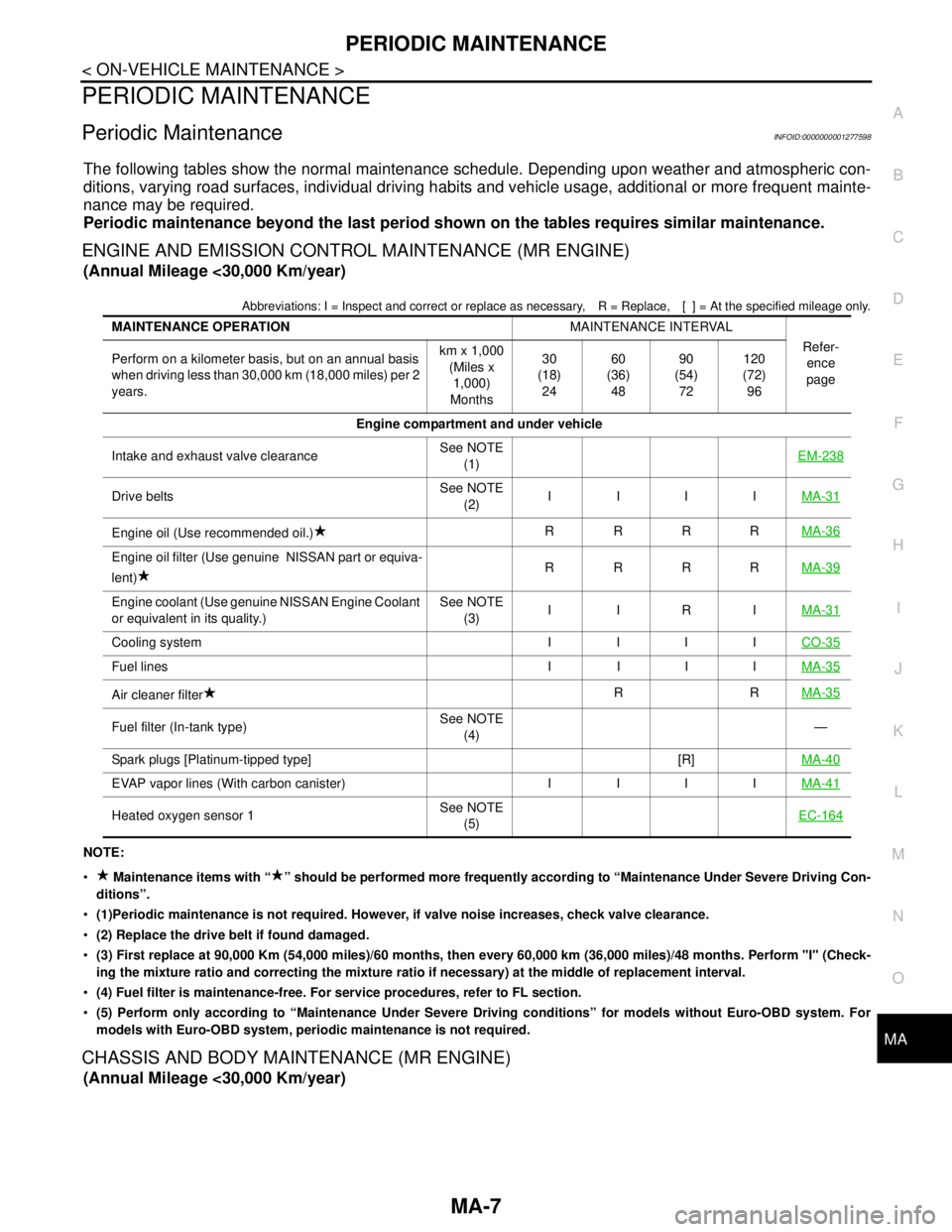
ENGINE AND EMISSION CONTROL MAINTENANCE (MR ENGINE)
(Annual Mileage <30,000 Km/year)
Abbreviations: I = Inspect and correct or replace as necessary, R = Replace, [ ] = At the specified mileage only.
NOTE:
Maintenance items with “ ” should be performed more frequently according to “Maintenance Under Severe Driving Con-
ditions”.
(1)Periodic maintenance is not required. However, if valve noise increases, check valve clearance.
(2) Replace the drive belt if found damaged.
(3) First replace at 90,000 Km (54,000 miles)/60 months, then every 60,000 km (36,000 miles)/48 months. Perform "I" (Check-
ing the mixture ratio and correcting the mixture ratio if necessary) at the middle of replacement interval.
(4) Fuel filter is maintenance-free. For service procedures, refer to FL section.
(5) Perform only according to “Maintenance Under Severe Driving conditions” for models without Euro-OBD system. For
models with Euro-OBD system, periodic maintenance is not required.
CHASSIS AND BODY MAINTENANCE (MR ENGINE)
(Annual Mileage <30,000 Km/year)
MAINTENANCE OPERATIONMAINTENANCE INTERVAL
Refer-
ence
page Perform on a kilometer basis, but on an annual basis
when driving less than 30,000 km (18,000 miles) per 2
years.km x 1,000
(Miles x
1,000)
Months30
(18)
2460
(36)
4890
(54)
72120
(72)
96
Engine compartment and under vehicle
Intake and exhaust valve clearanceSee NOTE
(1)EM-238
Drive beltsSee NOTE
(2)IIIIMA-31
Engine oil (Use recommended oil.)RRRRMA-36
Engine oil filter (Use genuine NISSAN part or equiva-
lent)RRRRMA-39
Engine coolant (Use genuine NISSAN Engine Coolant
or equivalent in its quality.)See NOTE
(3)IIRIMA-31
Cooling system I I I ICO-35
Fuel lines I I I IMA-35
Air cleaner filterRRMA-35
Fuel filter (In-tank type)See NOTE
(4)—
Spark plugs [Platinum-tipped type] [R]MA-40
EVAP vapor lines (With carbon canister) I I I IMA-41
Heated oxygen sensor 1See NOTE
(5)EC-164
Page 4249 of 5883
PERIODIC MAINTENANCE
MA-9
< ON-VEHICLE MAINTENANCE >
C
D
E
F
G
H
I
J
K
L
MB
MAN
OA
NOTE:
Maintenance items with “ ” should be performed more frequently according to “Maintenance Under Severe Driving Con-
ditions”.
(1)Periodic maintenance is not required. However, if valve noise increases, check valve clearance.
(2) Replace the drive belt if found damaged.
(3) First replace at 90,000 Km (54,000 miles)/60 months, then every 60,000 km (36,000 miles)/48 months. Perform "I" (Check-
ing the mixture ratio and correcting the mixture ratio if necessary) at the middle of replacement interval.
(4) Fuel filter is maintenance-free. For service procedures, refer to FL section.
(5) Perform only according to “Maintenance Under Severe Driving conditions” for models without Euro-OBD system. For
models with Euro-OBD system, periodic maintenance is not required.
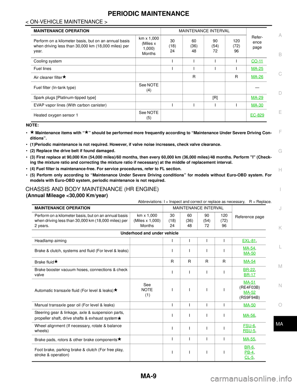
CHASSIS AND BODY MAINTENANCE (HR ENGINE)
(Annual Mileage <30,000 Km/year)
Abbreviations: I = Inspect and correct or replace as necessary, R = Replace.
Cooling system I I I ICO-11
Fuel lines I I I IMA-25
Air cleaner filterRRMA-26
Fuel filter (In-tank type)See NOTE
(4)—
Spark plugs [Platinum-tipped type] [R]MA-29
EVAP vapor lines (With carbon canister) I I I IMA-30
Heated oxygen sensor 1See NOTE
(5)EC-829
MAINTENANCE OPERATIONMAINTENANCE INTERVAL
Refer-
ence
page Perform on a kilometer basis, but on an annual basis
when driving less than 30,000 km (18,000 miles) per
year.km x 1,000
(Miles x
1,000)
Months30
(18)
2460
(36)
4890
(54)
72120
(72)
96
MAINTENANCE OPERATIONMAINTENANCE INTERVAL
Reference page Perform on a kilometer basis, but on an annual basis
when driving less than 30,000 km (18,000 miles) per
2 years.km x 1,000
(Miles x 1,000)
Months30
(18)
2460
(36)
4890
(54)
72120
(72)
96
Underhood and under vehicle
Headlamp aiming IIIIEXL-81
,
Brake & clutch, systems and fluid (For level & leaks) IIIIMA-54
,
MA-50
Brake fluidRRRRMA-54
Brake booster vacuum hoses, connections & check
valveIIIIBR-22,
BR-17
Automatic transaxle fluid (For level & leaks)See
NOTE
(1)IIIIMA-51(RE4F03B)
MA-52
(RS9F94B)
Manual transaxle gear oil (For level & leaks) IIIIMA-50
Steering gear & linkage, axle & suspension parts,
propeller shaft, drive shafts & exhaust systemIIIIMA-56,
Wheel alignment (If necessary, rotate & balance
wheels)IIIIFSU-6
,
RSU-5
,
Brake pads, rotors & other brake componentsIIIIMA-55
,
Foot brake, parking brake & clutch (For free play,
stroke & operation)IIIIBR-6
,
PB-4
,
CL-5
,
Page 4253 of 5883
PERIODIC MAINTENANCE
MA-13
< ON-VEHICLE MAINTENANCE >
C
D
E
F
G
H
I
J
K
L
MB
MAN
OA
Abbreviations: I = Inspect and correct or replace as necessary, R = Replace,.
NOTE:
Maintenance items with “ ” should be performed more frequently according to “Maintenance Under Severe Driving Con-
ditions”.
(1)Periodic maintenance is not required. However, if valve noise increases, check valve clearance.
(2) Replace the drive belt if found damaged.
(3) First replace at 90,000 Km (54,000 miles), then every 60,000 km (36,000 miles). Perform "I" (Checking the mixture ratio and
correcting the mixture ratio if necessary) at the middle of replacement interval.
(4) Fuel filter is maintenance-free. For service procedures, refer to FL section.
(5) Perform only according to “Maintenance Under Severe Driving conditions” for models without Euro-OBD system. For
models with Euro-OBD system, periodic maintenance is not required.
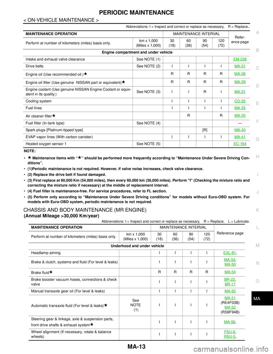
CHASSIS AND BODY MAINTENANCE (MR ENGINE)
(Annual Mileage >30,000 Km/year)
Abbreviations: I = Inspect and correct or replace as necessary, R = Replace, L = Lubricate.
MAINTENANCE OPERATIONMAINTENANCE INTERVAL
Refer-
ence page
Perform at number of kilometers (miles) basis only.km x 1,000
(Miles x 1,000)30
(18)60
(36)90
(54)120
(72)
Engine compartment and under vehicle
Intake and exhaust valve clearance See NOTE (1)EM-238
Drive belts See NOTE (2) I I I IMA-31
Engine oil (Use recommended oil.)RRRRMA-36
Engine oil filter (Use genuine NISSAN part or equivalent)RRRRMA-39
Engine coolant (Use genuine NISSAN Engine Coolant or equiv-
alent in its quality.)See NOTE (3) I I R IMA-31
Cooling system I I I ICO-35
Fuel linesI IIIMA-35
Air cleaner filterRRMA-35
Fuel filter (In-tank type) See NOTE (4) —
Spark plugs [Platinum-tipped type] [R]MA-40
EVAP vapor lines (With carbon canister) I I I IMA-41
Heated oxygen sensor 1 See NOTE (5)EC-164
MAINTENANCE OPERATIONMAINTENANCE INTERVAL
Reference page
Perform at number of kilometers (miles) basis only.km x 1,000
(Miles x 1,000)30
(18)60
(36)90
(54)120
(72)
Underhood and under vehicle
Headlamp aiming I I I IEXL-81
,
Brake & clutch, systems and fluid (For level & leaks) I I I IMA-54
,
MA-50
Brake fluidRRRRMA-54
Brake booster vacuum hoses, connections & check
valveIIIIBR-22,
BR-17
Manual transaxle gear oil (For level & leaks) I I I IMA-50
Automatic transaxle fluid (For level & leaks)See
NOTE
(1)IIIIMA-51(RE4F03B)
MA-52
(RS9F94B)
Steering gear & linkage, axle & suspension parts,
front drive shafts & exhaust systemIIIIMA-56
,
Wheel alignment (If necessary, rotate & balance
wheels)IIIIFSU-6
,
RSU-5
,
Page 4254 of 5883
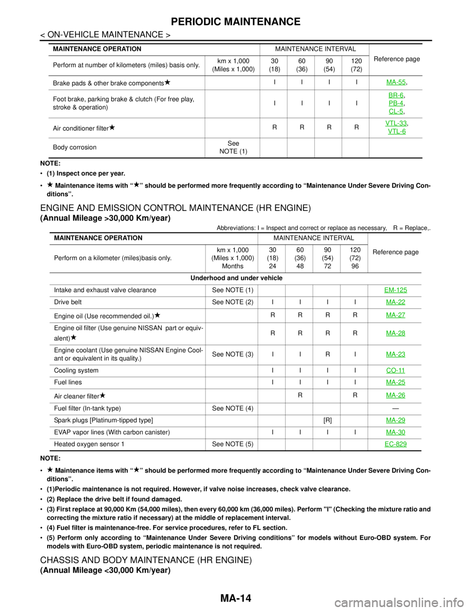
MA-14
< ON-VEHICLE MAINTENANCE >
PERIODIC MAINTENANCE
NOTE:
(1) Inspect once per year.
Maintenance items with “ ” should be performed more frequently according to “Maintenance Under Severe Driving Con-
ditions”.
ENGINE AND EMISSION CONTROL MAINTENANCE (HR ENGINE)
(Annual Mileage >30,000 Km/year)
Abbreviations: I = Inspect and correct or replace as necessary, R = Replace,.
NOTE:
Maintenance items with “ ” should be performed more frequently according to “Maintenance Under Severe Driving Con-
ditions”.
(1)Periodic maintenance is not required. However, if valve noise increases, check valve clearance.
(2) Replace the drive belt if found damaged.
(3) First replace at 90,000 Km (54,000 miles), then every 60,000 km (36,000 miles). Perform "I" (Checking the mixture ratio and
correcting the mixture ratio if necessary) at the middle of replacement interval.
(4) Fuel filter is maintenance-free. For service procedures, refer to FL section.
(5) Perform only according to “Maintenance Under Severe Driving conditions” for models without Euro-OBD system. For
models with Euro-OBD system, periodic maintenance is not required.
CHASSIS AND BODY MAINTENANCE (HR ENGINE)
(Annual Mileage <30,000 Km/year)
Brake pads & other brake componentsIIIIMA-55,
Foot brake, parking brake & clutch (For free play,
stroke & operation)IIIIBR-6
,
PB-4
,
CL-5
,
Air conditioner filterRRRRVTL-33
,
VTL-6
Body corrosionSee
NOTE (1) MAINTENANCE OPERATIONMAINTENANCE INTERVAL
Reference page
Perform at number of kilometers (miles) basis only.km x 1,000
(Miles x 1,000)30
(18)60
(36)90
(54)120
(72)
MAINTENANCE OPERATIONMAINTENANCE INTERVAL
Reference page
Perform on a kilometer (miles)basis only.km x 1,000
(Miles x 1,000)
Months30
(18)
2460
(36)
4890
(54)
72120
(72)
96
Underhood and under vehicle
Intake and exhaust valve clearance See NOTE (1)EM-125
Drive belt See NOTE (2)IIIIMA-22
Engine oil (Use recommended oil.)RRRRMA-27
Engine oil filter (Use genuine NISSAN part or equiv-
alent)RRRRMA-28
Engine coolant (Use genuine NISSAN Engine Cool-
ant or equivalent in its quality.)See NOTE (3) I I R IMA-23
Cooling system IIIICO-11
Fuel lines IIIIMA-25
Air cleaner filterRRMA-26
Fuel filter (In-tank type) See NOTE (4) —
Spark plugs [Platinum-tipped type] [R]MA-29
EVAP vapor lines (With carbon canister) IIIIMA-30
Heated oxygen sensor 1 See NOTE (5)EC-829
Page 4293 of 5883
CHASSIS AND BODY MAINTENANCE
MA-53
< ON-VEHICLE MAINTENANCE >
C
D
E
F
G
H
I
J
K
L
MB
MAN
OA
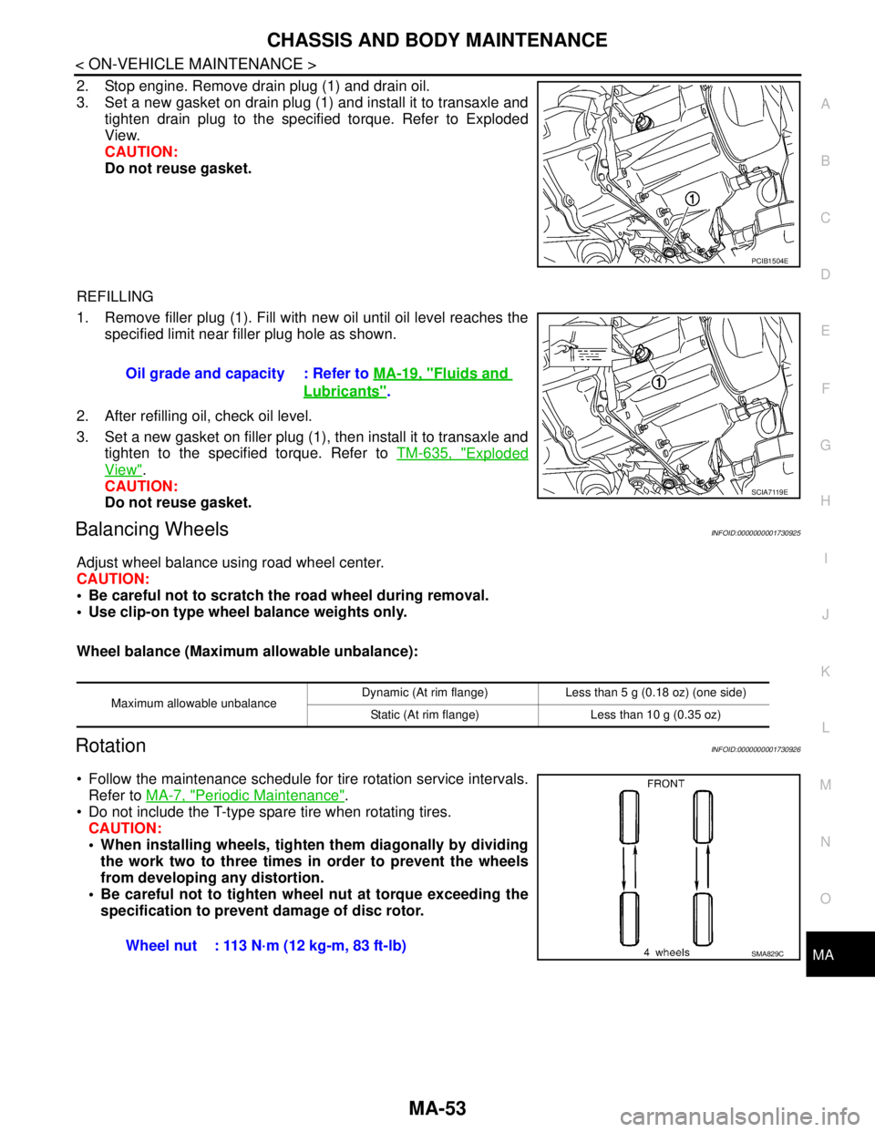
2. Stop engine. Remove drain plug (1) and drain oil.
3. Set a new gasket on drain plug (1) and install it to transaxle and
tighten drain plug to the specified torque. Refer to Exploded
View.
CAUTION:
Do not reuse gasket.
REFILLING
1. Remove filler plug (1). Fill with new oil until oil level reaches the
specified limit near filler plug hole as shown.
2. After refilling oil, check oil level.
3. Set a new gasket on filler plug (1), then install it to transaxle and
tighten to the specified torque. Refer to TM-635, "
Exploded
View".
CAUTION:
Do not reuse gasket.
Balancing WheelsINFOID:0000000001730925
Adjust wheel balance using road wheel center.
CAUTION:
Be careful not to scratch the road wheel during removal.
Use clip-on type wheel balance weights only.
Wheel balance (Maximum allowable unbalance):
RotationINFOID:0000000001730926
Follow the maintenance schedule for tire rotation service intervals.
Refer to MA-7, "
Periodic Maintenance".
Do not include the T-type spare tire when rotating tires.
CAUTION:
When installing wheels, tighten them diagonally by dividing
the work two to three times in order to prevent the wheels
from developing any distortion.
Be careful not to tighten wheel nut at torque exceeding the
specification to prevent damage of disc rotor.
PCIB1504E
Oil grade and capacity : Refer to MA-19, "Fluids and
Lubricants".
SCIA7119E
Maximum allowable unbalanceDynamic (At rim flange) Less than 5 g (0.18 oz) (one side)
Static (At rim flange) Less than 10 g (0.35 oz)
Wheel nut : 113 N·m (12 kg-m, 83 ft-lb)SMA829C
Page 5801 of 5883
WT-6
< ON-VEHICLE REPAIR >
ROAD WHEEL TIRE ASSEMBLY
ON-VEHICLE REPAIR
ROAD WHEEL TIRE ASSEMBLY
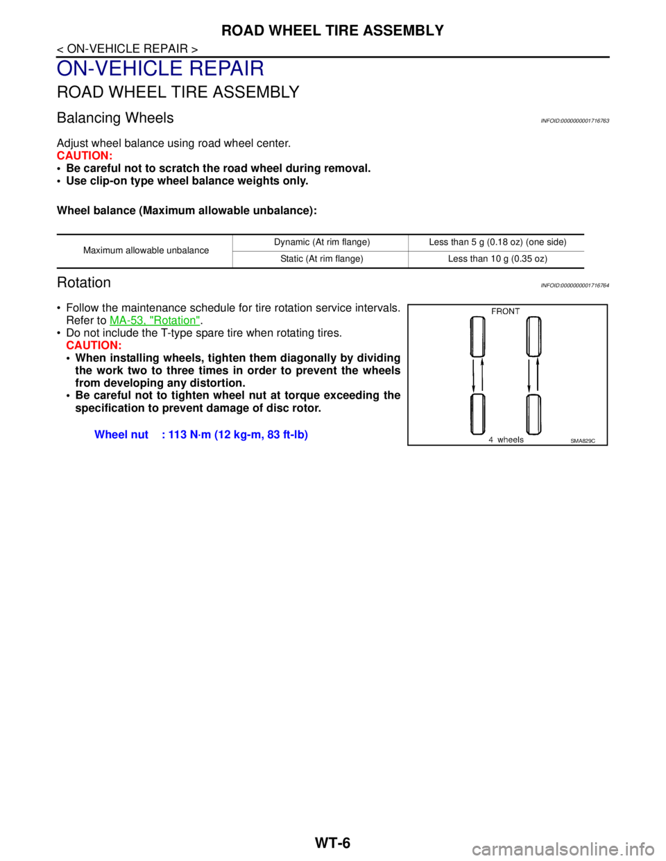
Balancing WheelsINFOID:0000000001716763
Adjust wheel balance using road wheel center.
CAUTION:
Be careful not to scratch the road wheel during removal.
Use clip-on type wheel balance weights only.
Wheel balance (Maximum allowable unbalance):
RotationINFOID:0000000001716764
Follow the maintenance schedule for tire rotation service intervals.
Refer to MA-53, "
Rotation".
Do not include the T-type spare tire when rotating tires.
CAUTION:
When installing wheels, tighten them diagonally by dividing
the work two to three times in order to prevent the wheels
from developing any distortion.
Be careful not to tighten wheel nut at torque exceeding the
specification to prevent damage of disc rotor.
Maximum allowable unbalanceDynamic (At rim flange) Less than 5 g (0.18 oz) (one side)
Static (At rim flange) Less than 10 g (0.35 oz)
Wheel nut : 113 N·m (12 kg-m, 83 ft-lb)SMA829C