transmission fluid NISSAN TIIDA 2007 Service Repair Manual
[x] Cancel search | Manufacturer: NISSAN, Model Year: 2007, Model line: TIIDA, Model: NISSAN TIIDA 2007Pages: 5883, PDF Size: 78.95 MB
Page 466 of 5883
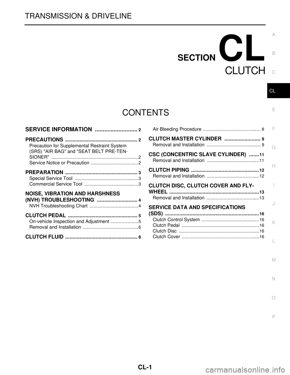
CL-1
TRANSMISSION & DRIVELINE
C
E
F
G
H
I
J
K
L
M
SECTION CL
A
B
CL
N
O
P
CONTENTS
CLUTCH
SERVICE INFORMATION ............................2
PRECAUTIONS ...................................................2
Precaution for Supplemental Restraint System
(SRS) "AIR BAG" and "SEAT BELT PRE-TEN-
SIONER" ...................................................................
2
Service Notice or Precaution .....................................2
PREPARATION ...................................................3
Special Service Tool .................................................3
Commercial Service Tool ..........................................3
NOISE, VIBRATION AND HARSHNESS
(NVH) TROUBLESHOOTING .............................
4
NVH Troubleshooting Chart ......................................4
CLUTCH PEDAL .................................................5
On-vehicle Inspection and Adjustment ......................5
Removal and Installation ...........................................6
CLUTCH FLUID ...................................................8
Air Bleeding Procedure .............................................8
CLUTCH MASTER CYLINDER .........................9
Removal and Installation ..........................................9
CSC (CONCENTRIC SLAVE CYLINDER) .......11
Removal and Installation .........................................11
CLUTCH PIPING ...............................................12
Removal and Installation .........................................12
CLUTCH DISC, CLUTCH COVER AND FLY-
WHEEL ..............................................................
13
Removal and Installation .........................................13
SERVICE DATA AND SPECIFICATIONS
(SDS) .................................................................
16
Clutch Control System .............................................16
Clutch Pedal ............................................................16
Clutch Disc ..............................................................16
Clutch Cover ............................................................16
Page 1739 of 5883

EC-390
< BASIC INSPECTION >[HR16DE (WITHOUT EURO-OBD)]
INSPECTION AND ADJUSTMENT
quirement
INFOID:0000000001161437
1.START
1. Make sure that accelerator pedal is fully released.
2. Turn ignition switch ON and wait at least 2 seconds.
3. Turn ignition switch OFF and wait at least 10 seconds.
4. Turn ignition switch ON and wait at least 2 seconds.
5. Turn ignition switch OFF and wait at least 10 seconds.
>> END
THROTTLE VALVE CLOSED POSITION LEARNING
THROTTLE VALVE CLOSED POSITION LEARNING : DescriptionINFOID:0000000001161438
Throttle Valve Closed Position Learning is a function of ECM to learn the fully closed position of the throttle
valve by monitoring the throttle position sensor output signal. It must be performed each time harness connec-
tor of electric throttle control actuator or ECM is disconnected.
THROTTLE VALVE CLOSED POSITION LEARNING : Special Repair Requirement
INFOID:0000000001161439
1.START
1. Make sure that accelerator pedal is fully released.
2. Turn ignition switch ON.
3. Turn ignition switch OFF and wait at least 10 seconds.
Make sure that throttle valve moves during above 10 seconds by confirming the operating sound.
>> END
IDLE AIR VOLUME LEARNING
IDLE AIR VOLUME LEARNING : DescriptionINFOID:0000000001161440
Idle Air Volume Learning is a function of ECM to learn the idle air volume that keeps each engine idle speed
within the specific range. It must be performed under any of the following conditions:
Each time electric throttle control actuator or ECM is replaced.
Idle speed or ignition timing is out of specification.
IDLE AIR VOLUME LEARNING : Special Repair RequirementINFOID:0000000001161441
1.PRECONDITIONING
Make sure that all of the following conditions are satisfied.
Learning will be cancelled if any of the following conditions are missed for even a moment.
Battery voltage: More than 12.9V (At idle)
Engine coolant temperature: 70 - 100°C (158 - 212°F)
Park/neutral position switch: ON
Electric load switch: OFF
(Air conditioner, headlamp, rear window defogger)
On vehicles equipped with daytime light systems, set lighting switch to the 1st position to light only
small lamps.
Steering wheel: Neutral (Straight-ahead position)
Vehicle speed: Stopped
Transmission: Warmed-up
- For A/T models
With CONSULT-III: Drive vehicle until “FLUID TEMP SE” in “DATA MONITOR” mode of “A/T” system indi-
cates less than 0.9V.
Without CONSULT-III: Drive vehicle for 10 minutes.
- For M/T models
Drive vehicle for 10 minutes.
Page 1818 of 5883

TROUBLE DIAGNOSIS - SPECIFICATION VALUE
EC-469
< COMPONENT DIAGNOSIS >[HR16DE (WITHOUT EURO-OBD)]
C
D
E
F
G
H
I
J
K
L
MA
EC
N
P O
COMPONENT DIAGNOSIS
TROUBLE DIAGNOSIS - SPECIFICATION VALUE
DescriptionINFOID:0000000001693221
The specification (SP) value indicates the tolerance of the value that is displayed in “SPEC” of “DATA MONI-
TOR” mode of CONSULT-III during normal operation of the Engine Control System. When the value in “SPEC”
of “DATA MONITOR” mode is within the SP value, the Engine Control System is confirmed OK. When the
value in “SPEC” of “DATA MONITOR” mode is NOT within the SP value, the Engine Control System may have
one or more malfunctions.
The SP value is used to detect malfunctions that may affect the Engine Control System, but will not light the
MI.
The SP value will be displayed for the following three items:
B/FUEL SCHDL (The fuel injection pulse width programmed into ECM prior to any learned on board correc-
tion)
A/F ALPHA-B1 (The mean value of air-fuel ratio feedback correction factor per cycle)
MAS A/F SE-B1 (The signal voltage of the mass air flow sensor)
Component Function CheckINFOID:0000000001693222
1.START
Make sure that all of the following conditions are satisfied.
Vehicle driven distance: More than 5,000 km (3,107 miles)
Barometric pressure: 98.3 - 104.3 kPa (0.983 - 1.043 bar, 1.003 - 1.064 kg/cm
2, 14.25 - 15.12 psi)
Atmospheric temperature: 20 - 30°C (68 - 86°F)
Engine coolant temperature: 75 - 95°C (167 - 203°F)
Transmission: Warmed-up
- A/T models: After the engine is warmed up to normal operating temperature, drive vehicle until “FLUID
TEMP SE” fluid temperature sensor signal) indicates more than 60°C (140°F).
- M/T models: After the engine is warmed up to normal operating temperature, drive vehicle for 5 minutes.
Electrical load: Not applied*
Engine speed: Idle
*: Rear window defogger switch, air conditioner switch, lighting switch are OFF. Steering wheel is straight
ahead.
>> GO TO 2.
2.PERFORM “SPEC” OF “DATA MONITOR” MODE
With CONSULT-III
NOTE:
Perform “SPEC” in “DATA MONITOR” mode in maximum scale display.
1. Perform EC-385, "
BASIC INSPECTION : Special Repair Requirement".
2. Select “B/FUEL SCHDL”, “A/F ALPHA-B1” and “MAS A/F SE-B1” in “SPEC” of “DATA MONITOR” mode
with CONSULT-III.
3. Make sure that monitor items are within the SP value.
Is the inspection result normal?
YES >> END
NO >> Go to EC-470, "
Diagnosis Procedure".
Page 2582 of 5883

ECM
EC-1233
< ECU DIAGNOSIS >[K9K]
C
D
E
F
G
H
I
J
K
L
MA
EC
N
P O Test Condition: Engine at Idle
Order Function Parameter Display and notes Trouble diagnosis
1 Fan speed request*FAN ASSEMBLY INACTIVE
NONE. FAN UNIT LOW -
FAN UNIT HIGH -
2Compressor
engagement requestDMND LNK COMPThe ECM requests the IPDM E/R
(via CAN communication line) to
start the compressor
ACTIVE: The CAN communica-
tion should not be suspected on
the Automatic Transmission,
IPDM E/R or Intelligent Key unit
or BCM system.
The Intelligent Key unit or BCM
should request the ECM to be
engaged.
The refrigerant pressure sensor
should not be suspected. Satis-
factory engine operating condi-
tions (engine coolant
temperature, engine load etc.).
INACTIVE: One of the above
conditions has not been met.NONE
3Fast idle speed re-
questACCEL IDL RQ INACTIVE NONE
4 Refrigerant pressureRFRGERNT PRSSIndicates the value in Bar for the
refrigerant fluid in the system.
Default value: 0 Bar.In the event of a malfunction, per-
form the trouble diagnosis for DTC
P0530 REFRUGERANT PRES-
SURE SENSOR.
RFRGERNT FLUID V 0.1V < RFRGERNT FLUID V <
4.8V
5Engine coolant tem-
peratureWATER TEMPClose to ambient temperature
(cold engine).
Indicates the engine coolant tem-
perature in °C.In the event of a malfunction, per-
form the trouble diagnosis for DTC
P0115 ECT SENSOR.
6 Vehicle speed VEHICLE SPEED0 km/h (mph)
Indicates the vehicle speed in km/h
(mph). This parameter is transmit-
ted by the “ABS actuator and elec-
tric unit (control unit)” or
combination meter via CAN com-
munication line.Perform the trouble diagnosis for
CAN communication line. Perform
the trouble diagnosis for “ABS ac-
tuator and electric unit (control
unit)” or combination meter.
Order Function Parameter Display and notes Trouble diagnosis
1 Fan speed request*FAN ASSEMBLY INACTIVE
NONE. FAN UNIT LOW -
FAN UNIT HIGH -
Page 2583 of 5883

EC-1234
< ECU DIAGNOSIS >[K9K]
ECM
CRUISE CONTROL/SPEED LIMITER SUB FUNCTION
Test Condition: Engine Stopped and Ignition Switch ON
Test Condition: Engine at Idle
PROTECTION SUBFUNCTION
Test Condition: Engine Stopped and Ignition Switch ON
2Compressor
engagement re-
questDMND LNK COMPThe ECM requests the IPDM E/R
(via CAN communication line) to
start the compressor
ACTIVE: The CAN communica-
tion should not be suspected on
the Automatic Transmission,
IPDM E/R or Intelligent Key unit
or BCM system.
The Intelligent Key unit or BCM
should request the ECM to be en-
gaged.
The refrigerant pressure sensor
should not be suspected. Satis-
factory engine operating condi-
tions (engine coolant
temperature, engine load etc.).
INACTIVE: One of the above
conditions has not been met.NONE
3Fast idle speed re-
questACCEL IDL RQINACTIVE
or
ACTIVE
(Air conditioning is operate)NONE
4Refrigerant pres-
sureRFRGERNT PRSSIndicates the value in Bar for the re-
frigerant fluid in the system.
Default value: 0 Bar.In the event of a malfunction, per-
form the trouble diagnosis for DTC
P0530 REFRUGERANT PRES-
SURE SENSOR.
RFRGERNT FLUID V 0.1V < RFRGERNT FLUID V< 4.8V
5Engine coolant
temperatureWATER TEMPIndicates the engine coolant tem-
perature in °C.In the event of a malfunction, per-
form the trouble diagnosis for DTC
P0115 ECT SENSOR.
6 Vehicle speed VEHICLE SPEED0 km/h (mph)
Indicates the vehicle speed in km/h
(mph). This parameter is transmit-
ted by the “ABS actuator and elec-
tric unit (control unit)” or
combination meter via CAN com-
munication line.Perform the trouble diagnosis for
CAN communication line. Perform
the trouble diagnosis for “ABS actu-
ator and electric unit (control unit)”
or combination meter. Order Function Parameter Display and notes Trouble diagnosis
Order Function Parameter Display and notes Trouble diagnosis
1Cruise control/speed
limiterCRS CN/S LMTR INACTIVEIn the event of a malfunction, per-
form the trouble diagnosis for DTC
P0575 ASCD STEERING SWITCH.
Order Function Parameter Display and notes Trouble diagnosis
1Cruise control/speed
limiterCRS CN/S LMTR INACTIVEIn the event of a malfunction, perform
the trouble diagnosis for DTC P0575
ASCD STEERING SWITCH.
Page 2705 of 5883

EM -58
< ON-VEHICLE REPAIR >[HR16DE]
TIMING CHAIN
Check for cracks and any excessive wear at link plates and roller
links of timing chain. Replace timing chain as necessary.
INSPECTION AFTER INSTALLATION
Inspection for Leaks
Before starting engine, check oil/fluid levels including engine coolant and engine oil. If less than required
quantity, fill to the specified level. Refer to MA-19, "
Fluids and Lubricants".
Use procedure below to check for fuel leakage.
- Turn ignition switch “ON” (with engine stopped). With fuel pressure applied to fuel piping, check for fuel leak-
age at connection points.
- Start engine. With engine speed increased, check again for fuel leakage at connection points.
Run engine to check for unusual noise and vibration.
NOTE:
If hydraulic pressure inside chain tensioner drops after removal/installation, slack in guide may generate a
pounding noise during and just after the engine start. However, this does not indicate an unusualness. Noise
will stop after hydraulic pressure rises.
Warm up engine thoroughly to make sure there is no leakage of fuel, or any oil/fluids including engine oil and
engine coolant.
Bleed air from lines and hoses of applicable lines, such as in cooling system.
After cooling down engine, again check oil/fluid levels including engine oil and engine coolant. Refill to the
specified level, if necessary.
Summary of the inspection items:
* Transmission/transaxle/CVT fluid, power steering fluid, brake fluid, etc.A: Crack
B: Wear
JPBIA0091ZZ
Items Before starting engine Engine running After engine stopped
Engine coolant Level Leakage Level
Engine oil Level Leakage Level
Other oils and fluid* Level Leakage Level
Fuel Leakage Leakage Leakage
Page 2722 of 5883

CAMSHAFT
EM-75
< ON-VEHICLE REPAIR >[HR16DE]
C
D
E
F
G
H
I
J
K
L
MA
EM
N
P O Inspection for Leaks
The following are procedures for checking fluids leak, lubricates leak.
Before starting engine, check oil/fluid levels including engine coolant and engine oil. If less than required
quantity, fill to the specified level. Refer to MA-19, "
Fluids and Lubricants".
Use procedure below to check for fuel leakage.
- Turn ignition switch “ON” (with engine stopped). With fuel pressure applied to fuel piping, check for fuel leak-
age at connection points.
- Start engine. With engine speed increased, check again for fuel leakage at connection points.
Run engine to check for unusual noise and vibration.
NOTE:
If hydraulic pressure inside timing chain tensioner drops after removal/installation, slack in the guide may
generate a pounding noise during and just after engine start. However, this is normal. Noise will stop after
hydraulic pressure rises.
Warm up engine thoroughly to make sure there is no leakage of fuel, or any oil/fluids including engine oil and
engine coolant.
Bleed air from lines and hoses of applicable lines, such as in cooling system.
After cooling down engine, again check oil/fluid levels including engine oil and engine coolant. Refill to the
specified level, if necessary.
Summary of the inspection items:
*: Transmission/transaxle/CVT fluid, power steering fluid, brake fluid, etc.
Inspection of Camshaft Sprocket (INT) Oil Groove
CAUTION:
Perform this inspection only when DTC P0011 is detected in self-diagnostic results of CONSULT-III
and it is directed according to inspection procedure of EC section. Refer to EC-131, "
Diagnosis Pro-
cedure" (EURO-OBD), EC-484, "Diagnosis Procedure" (WITHOUT EURO-OBD).
Check when engine is cold so as to prevent burns from the splashing engine oil.
1. Check engine oil level. Refer to LU-6, "
Inspection".
2. Perform the following procedure so as to prevent the engine from being unintentionally started while
checking.
a. Release the fuel pressure. Refer to EC-377, "
Inspection" (EURO-OBD), EC-681, "Inspection" (WITHOUT
EURO-OBD).
b. Remove intake manifold. Refer to EM-29, "
Exploded View".
c. Disconnect ignition coil and injector harness connectors. Refer to EM-47, "
Exploded View".
3. Remove intake valve timing control solenoid valve. Refer to EM-50, "
Exploded View".
4. Crank engine, and then make sure that engine oil comes out
from intake valve timing control solenoid valve hole (A). End
crank after checking.
WARNING:
Be careful not to touch rotating parts (drive belts, idler pul-
ley, and crankshaft pulley, etc.).
CAUTION:
Prevent splashing by using a shop cloth so as to prevent
the worker from injury from engine oil and so as to prevent engine oil contamination.
Prevent splashing by using a shop cloth so as to prevent engine oil from being splashed to
engine and vehicle. Especially, be careful not to apply engine oil to rubber parts of drive belts,
engine mounting insulator, etc. Wipe engine oil off immediately if it is splashed.
Items Before starting engine Engine running After engine stopped
Engine coolant Level Leakage Level
Engine oil Level Leakage Level
Other oils and fluid* Level Leakage Level
Fuel Leakage Leakage Leakage
1: Plug
:Engine front
PBIC3706E
Page 2729 of 5883

EM-82
< ON-VEHICLE REPAIR >[HR16DE]
CYLINDER HEAD
In this step, loosen bolts in reverse order of that indicated.
d. Tighten all bolts.
e. Turn all bolts 75 degrees clockwise (angle tightening).
CAUTION:
Check and confirm the tightening angle by using the angle
wrench [SST: KV10112100] (A) or protractor. Avoid judg-
ment by visual inspection without the tool.
f. Turn all bolts 75 degrees clockwise again (angle tightening).
3. Installation is in the reverse order of removal, for the remaining parts.
INSPECTION AFTER INSTALLATION
Inspection for Leaks
Before starting engine, check oil/fluid levels including engine coolant and engine oil. If less than required
quantity, fill to the specified level. Refer to MA-19, "
Fluids and Lubricants".
Use procedure below to check for fuel leakage.
- Turn ignition switch “ON” (with engine stopped). With fuel pressure applied to fuel piping, check for fuel leak-
age at connection points.
- Start engine. With engine speed increased, check again for fuel leakage at connection points.
Run engine to check for unusual noise and vibration.
Warm up engine thoroughly to make sure there is no leakage of fuel, exhaust gases, or any oil/fluids includ-
ing engine oil and engine coolant.
Bleed air from lines and hoses of applicable lines, such as in cooling system.
After cooling down engine, again check oil/fluid levels including engine oil and engine coolant. Refill to the
specified level, if necessary.
Summary of the inspection items:
*: Transmission/transaxle/CVT fluid, power steering fluid, brake fluid, etc.
Disassembly and AssemblyINFOID:0000000001381422
: 40.0 N·m (4.1 kg-m, 30 ft-lb)
PBIC3733E
Items Before starting engine Engine running After engine stopped
Engine coolant Level Leakage Level
Engine oil Level Leakage Level
Other oils and fluid* Level Leakage Level
Fuel Leakage Leakage Leakage
Exhaust gases — Leakage —
Page 2737 of 5883

EM-90
< REMOVAL AND INSTALLATION >[HR16DE]
ENGINE ASSEMBLY
If items or work required are not covered by the engine section, follow the procedures in the applica-
ble sections.
Always use the support point specified for lifting.
Use either 2-pole lift type or separate type lift as best you can. If board-on type is used for unavoid-
able reasons, support at the rear axle jacking point with a transmission jack or similar tool before
starting work, in preparation for the backward shift of center of gravity.
For supporting points for lifting and jacking point at rear axle, refer to GI-48, "
Garage Jack and
Safety Stand and 2-Pole Lift".
REMOVAL
Outline
Remove the engine and the transaxle assembly from the vehicle downward. Separate the engine and the tran-
saxle.
Preparation
1. Remove the hood assembly. Refer to DLK-214, "Removal and Installation".
2. Remove the cowl top cover and cowl top extension assembly. Refer to EXT-20, "
Removal and Installa-
tion".
3. Release fuel pressure. Refer to EC-377, "
Inspection" (EURO-OBD), EC-681, "Inspection" (WITHOUT
EURO-OBD).
4. Drain engine coolant from radiator. Refer to CO-11, "
Changing Engine Coolant".
CAUTION:
Perform this step when the engine is cold.
Never spill engine coolant on drive belt.
5. Drain the transmission fluid. Refer to TM-628, "
Draining" (M/T models), TM-171, "Changing A/T Fluid" (A/
T models).
6. Remove the following parts.
Engine undercover
Front road wheels and tires: Refer to WT-6, "
Rotation".
Front fender protector (RH and LH): Refer to EXT-22, "
Removal and Installation".
Battery and battery tray: Refer to PG-6, "
Removal and Installation".
Drive belt: Refer to EM-16, "
Removal and Installation".
Air duct and air cleaner case assembly: Refer to EM-27, "
Exploded View".
Radiator hose (upper and lower): Refer to CO-16, "
Component".
Disconnect cooling fan controller wiring harness.
Remove coolant reservoir tank.
Remove fan shroud and cooling fan assembly. Refer to CO-16, "
Component".
Engine Room LH
1. Disconnect all connections of engine harness around the engine mounting insulator (LH), and then tem-
porarily secure the engine harness into the engine side.
CAUTION:
Protect connectors using a resin bag against foreign materials.
2. Remove ground cable at transaxle side.
3. Disconnect fuel feed hose at engine side. Refer to EM-35, "
Exploded View".
4. Disconnect EVAP purge hose and brake booster vacuum hose.
5. Disconnect heater hoses, and install plugs them to prevent engine coolant from draining. Refer to CO-24,
"Exploded View".
6. Disconnect control linkage from transaxle. Refer to TM-189, "
Exploded View" (A/T), TM-630, "Exploded
View" (M/T).
7. Disconnect the clutch tube at transmission side. Refer to CL-12, "
Removal and Installation".
Engine Room RH
1. Remove ground cable between front cover and vehicle.
2. Remove generator and generator bracket; Refer to CHG-15, "
Removal and Installation".
3. Remove A/C compressor with piping connected from the engine. Temporarily secure it on the vehicle side
with a rope to avoid putting load on it. (with A/C models) Refer to HA-34, "
Removal and Installation of
Compressor - HR16DE".
Page 2740 of 5883

ENGINE ASSEMBLY
EM-93
< REMOVAL AND INSTALLATION >[HR16DE]
C
D
E
F
G
H
I
J
K
L
MA
EM
N
P O
Summary of the inspection items:
*: Transmission/transaxle/CVT fluid, power steering fluid, brake fluid, etc.Items Before starting engine Engine running After engine stopped
Engine coolant Level Leakage Level
Engine oil Level Leakage Level
Other oils and fluid* Level Leakage Level
Fuel Leakage Leakage Leakage
Exhaust gases — Leakage —