light NISSAN TIIDA 2008 Service Owners Manual
[x] Cancel search | Manufacturer: NISSAN, Model Year: 2008, Model line: TIIDA, Model: NISSAN TIIDA 2008Pages: 2771, PDF Size: 60.61 MB
Page 1266 of 2771
EC-192
< SERVICE INFORMATION >
DTC P0122, P0123 TP SENSOR
DTC P0122, P0123 TP SENSOR
Component DescriptionINFOID:0000000001702679
Electric throttle control actuator consists of throttle control motor,
throttle position sensor, etc. The throttle position sensor responds to
the throttle valve movement.
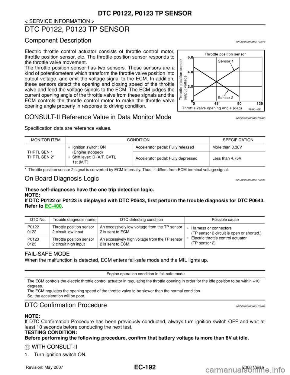
The throttle position sensor has two sensors. These sensors are a
kind of potentiometers which transform the throttle valve position into
output voltage, and emit the voltage signal to the ECM. In addition,
these sensors detect the opening and closing speed of the throttle
valve and feed the voltage signals to the ECM. The ECM judges the
current opening angle of the throttle valve from these signals and the
ECM controls the throttle control motor to make the throttle valve
opening angle properly in response to driving condition.
CONSULT-II Reference Value in Data Monitor ModeINFOID:0000000001702680
Specification data are reference values.
*: Throttle position sensor 2 signal is converted by ECM internally. Thus, it differs from ECM terminal voltage signal.
On Board Diagnosis LogicINFOID:0000000001702681
These self-diagnoses have the one trip detection logic.
NOTE:
If DTC P0122 or P0123 is displayed with DTC P0643, first perform the trouble diagnosis for DTC P0643.
Refer to EC-400
.
FAIL-SAFE MODE
When the malfunction is detected, ECM enters fail-safe mode and the MIL lights up.
DTC Confirmation ProcedureINFOID:0000000001702682
NOTE:
If DTC Confirmation Procedure has been previously conducted, always turn ignition switch OFF and wait at
least 10 seconds before conducting the next test.
TESTING CONDITION:
Before performing the following procedure, confirm that battery voltage is more than 8V at idle.
WITH CONSULT-II
1. Turn ignition switch ON.
PBIB0145E
MONITOR ITEM CONDITION SPECIFICATION
THRTL SEN 1
THRTL SEN 2*• Ignition switch: ON
(Engine stopped)
• Shift lever: D (A/T, CVT),
1st (M/T)Accelerator pedal: Fully released More than 0.36V
Accelerator pedal: Fully depressed Less than 4.75V
DTC No. Trouble diagnosis name DTC detecting condition Possible cause
P0122
0122Throttle position sensor
2 circuit low inputAn excessively low voltage from the TP sensor
2 is sent to ECM.• Harness or connectors
(TP sensor 2 circuit is open or shorted.)
• Electric throttle control actuator
(TP sensor 2) P0123
0123Throttle position sensor
2 circuit high inputAn excessively high voltage from the TP sensor
2 is sent to ECM.
Engine operation condition in fail-safe mode
The ECM controls the electric throttle control actuator in regulating the throttle opening in order for the idle position to be within +10
degrees.
The ECM regulates the opening speed of the throttle valve to be slower than the normal condition.
So, the acceleration will be poor.
Page 1331 of 2771

DTC P0171 FUEL INJECTION SYSTEM FUNCTION
EC-257
< SERVICE INFORMATION >
C
D
E
F
G
H
I
J
K
L
MA
EC
N
P O
DTC P0171 FUEL INJECTION SYSTEM FUNCTION
On Board Diagnosis LogicINFOID:0000000001702760
With the Air/Fuel Mixture Ratio Self-Learning Control, the actual mixture ratio can be brought closely to the
theoretical mixture ratio based on the mixture ratio feedback signal from the air fuel ratio (A/F) sensor 1. The
ECM calculates the necessary compensation to correct the offset between the actual and the theoretical
ratios. In case the amount of the compensation value is extremely large (The actual mixture ratio is too lean.),
the ECM judges the condition as the fuel injection system malfunction and lights up the MIL (2 trip detection
logic).
DTC Confirmation ProcedureINFOID:0000000001702761
NOTE:
If DTC Confirmation Procedure has been previously conducted, always turn ignition switch OFF and wait at
least 10 seconds before conducting the next test.
WITH CONSULT-II
1. Start engine and warm it up to normal operating temperature.
2. Turn ignition switch OFF and wait at least 10 seconds.
3. Turn ignition switch ON and select “SELF-LEARNING CONT” in “WORK SUPPORT” mode with CON-
SULT-II.
4. Clear the self-learning control coefficient by touching “CLEAR”.
5. Select “DATA MONITOR” mode with CONSULT-II.
6. Start engine again and let it idle for at least 10 minutes.
The 1st trip DTC P0171 should be detected at this stage, if a
malfunction exists. If so, go to EC-260, "
Diagnosis Procedure".
NOTE:
If 1st trip DTC is not detected during above procedure, perform-
ing the following procedure is advised.
a. Turn ignition switch OFF and wait at least 10 seconds.
b. Start engine and drive the vehicle under the similar conditions to
(1st trip) Freeze Frame Data for 10 minutes. Refer to the table
below.
Hold the accelerator pedal as steady as possible.
The similar conditions to (1st trip) Freeze Frame Data means the vehicle operation that the following con-
ditions should be satisfied at the same time.
Sensor Input Signal to ECM ECM function Actuator
Air fuel ratio (A/F) sensor 1Density of oxygen in exhaust gas
(Mixture ratio feedback signal)Fuel injection control Fuel injector
DTC No.Trouble diagnosis
nameDTC detecting condition Possible cause
P0171
0171Fuel injection system
too lean• Fuel injection system does not operate properly.
• The amount of mixture ratio compensation is too
large. (The mixture ratio is too lean.)• Intake air leaks
• Air fuel ratio (A/F) sensor 1
• Fuel injector
• Exhaust gas leaks
• Incorrect fuel pressure
• Lack of fuel
• Mass air flow sensor
• Incorrect PCV hose connection
SEF215Z
Engine speed Engine speed in the freeze frame data ± 400 rpm
Vehicle speed Vehicle speed in the freeze frame data ± 10 km/h (6 MPH)
Page 1338 of 2771

EC-264
< SERVICE INFORMATION >
DTC P0172 FUEL INJECTION SYSTEM FUNCTION
DTC P0172 FUEL INJECTION SYSTEM FUNCTION
On Board Diagnosis LogicINFOID:0000000001702764
With the Air/Fuel Mixture Ratio Self-Learning Control, the actual mixture ratio can be brought closely to the
theoretical mixture ratio based on the mixture ratio feedback signal from the air fuel ratio (A/F) sensor 1. The
ECM calculates the necessary compensation to correct the offset between the actual and the theoretical
ratios. In case the amount of the compensation value is extremely large (The actual mixture ratio is too rich.),
the ECM judges the condition as the fuel injection system malfunction and lights up the MIL (2 trip detection
logic).
DTC Confirmation ProcedureINFOID:0000000001702765
NOTE:
If DTC Confirmation Procedure has been previously conducted, always turn ignition switch OFF and wait at
least 10 seconds before conducting the next test.
WITH CONSULT-II
1. Start engine and warm it up to normal operating temperature.
2. Turn ignition switch OFF and wait at least 10 seconds.
3. Turn ignition switch ON and select “SELF-LEARNING CONT” in “WORK SUPPORT” mode with CON-
SULT-II.
4. Clear the self-learning control coefficient by touching “CLEAR”.
5. Select “DATA MONITOR” mode with CONSULT-II.
6. Start engine again and let it idle for at least 10 minutes.
The 1st trip DTC P0172 should be detected at this stage, if a
malfunction exists. If so, go to EC-267, "
Diagnosis Procedure".
NOTE:
If 1st trip DTC is not detected during above procedure, perform-
ing the following procedure is advised.
a. Turn ignition switch OFF and wait at least 10 seconds.
b. Start engine and drive the vehicle under the similar conditions to
(1st trip) Freeze Frame Data for 10 minutes. Refer to the table
below.
Hold the accelerator pedal as steady as possible.
The similar conditions to (1st trip) Freeze Frame Data means the vehicle operation that the following con-
ditions should be satisfied at the same time.
Sensor Input Signal to ECM ECM function Actuator
Air fuel ratio (A/F) sensor 1Density of oxygen in exhaust gas
(Mixture ratio feedback signal)Fuel injection control Fuel injector
DTC No.Trouble diagnosis
nameDTC detecting condition Possible cause
P0172
0172Fuel injection system
too rich• Fuel injection system does not operate properly.
• The amount of mixture ratio compensation is too
large. (The mixture ratio is too rich.)• Air fuel ratio (A/F) sensor 1
• Fuel injector
• Exhaust gas leaks
• Incorrect fuel pressure
• Mass air flow sensor
SEF215Z
Engine speed Engine speed in the freeze frame data ± 400 rpm
Vehicle speed Vehicle speed in the freeze frame data ± 10 km/h (6 MPH)
Page 1352 of 2771
EC-278
< SERVICE INFORMATION >
DTC P0222, P0223 TP SENSOR
DTC P0222, P0223 TP SENSOR
Component DescriptionINFOID:0000000001702782
Electric throttle control actuator consists of throttle control motor,
throttle position sensor, etc. The throttle position sensor responds to
the throttle valve movement.
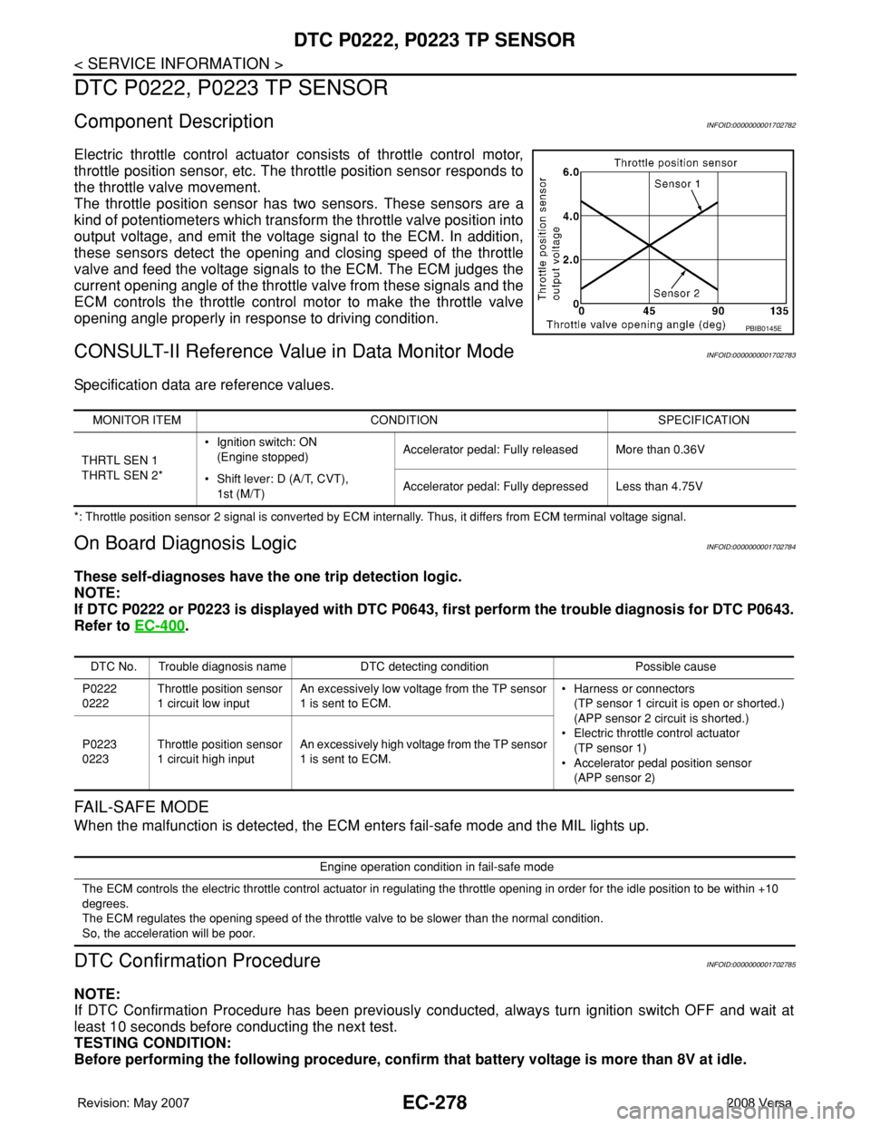
The throttle position sensor has two sensors. These sensors are a
kind of potentiometers which transform the throttle valve position into
output voltage, and emit the voltage signal to the ECM. In addition,
these sensors detect the opening and closing speed of the throttle
valve and feed the voltage signals to the ECM. The ECM judges the
current opening angle of the throttle valve from these signals and the
ECM controls the throttle control motor to make the throttle valve
opening angle properly in response to driving condition.
CONSULT-II Reference Value in Data Monitor ModeINFOID:0000000001702783
Specification data are reference values.
*: Throttle position sensor 2 signal is converted by ECM internally. Thus, it differs from ECM terminal voltage signal.
On Board Diagnosis LogicINFOID:0000000001702784
These self-diagnoses have the one trip detection logic.
NOTE:
If DTC P0222 or P0223 is displayed with DTC P0643, first perform the trouble diagnosis for DTC P0643.
Refer to EC-400
.
FAIL-SAFE MODE
When the malfunction is detected, the ECM enters fail-safe mode and the MIL lights up.
DTC Confirmation ProcedureINFOID:0000000001702785
NOTE:
If DTC Confirmation Procedure has been previously conducted, always turn ignition switch OFF and wait at
least 10 seconds before conducting the next test.
TESTING CONDITION:
Before performing the following procedure, confirm that battery voltage is more than 8V at idle.
PBIB0145E
MONITOR ITEM CONDITION SPECIFICATION
THRTL SEN 1
THRTL SEN 2*• Ignition switch: ON
(Engine stopped)Accelerator pedal: Fully released More than 0.36V
• Shift lever: D (A/T, CVT),
1st (M/T)Accelerator pedal: Fully depressed Less than 4.75V
DTC No. Trouble diagnosis name DTC detecting condition Possible cause
P0222
0222Throttle position sensor
1 circuit low inputAn excessively low voltage from the TP sensor
1 is sent to ECM.• Harness or connectors
(TP sensor 1 circuit is open or shorted.)
(APP sensor 2 circuit is shorted.)
• Electric throttle control actuator
(TP sensor 1)
• Accelerator pedal position sensor
(APP sensor 2) P0223
0223Throttle position sensor
1 circuit high inputAn excessively high voltage from the TP sensor
1 is sent to ECM.
Engine operation condition in fail-safe mode
The ECM controls the electric throttle control actuator in regulating the throttle opening in order for the idle position to be within +10
degrees.
The ECM regulates the opening speed of the throttle valve to be slower than the normal condition.
So, the acceleration will be poor.
Page 1358 of 2771
EC-284
< SERVICE INFORMATION >
DTC P0300 - P0304 MULTIPLE CYLINDER MISFIRE, NO. 1 - 4 CYLINDER MIS-
FIRE
DTC P0300 - P0304 MULTIPLE CYLINDER MISFIRE, NO. 1 - 4 CYLINDER
MISFIRE
On Board Diagnosis LogicINFOID:0000000001702790
When a misfire occurs, engine speed will fluctuate. If the engine speed fluctuates enough to cause the crank-
shaft position (CKP) sensor (POS) signal to vary, ECM can determine that a misfire is occurring.
The misfire detection logic consists of the following two conditions.
1. One Trip Detection Logic (Three Way Catalyst Damage)
On the 1st trip that a misfire condition occurs that can damage the three way catalyst (TWC) due to over-
heating, the MIL will blink.
When a misfire condition occurs, the ECM monitors the CKP sensor (POS) signal every 200 engine revo-
lutions for a change.
When the misfire condition decreases to a level that will not damage the TWC, the MIL will turn off.
If another misfire condition occurs that can damage the TWC on a second trip, the MIL will blink.
When the misfire condition decreases to a level that will not damage the TWC, the MIL will remain on.
If another misfire condition occurs that can damage the TWC, the MIL will begin to blink again.
2. Two Trip Detection Logic (Exhaust quality deterioration)
For misfire conditions that will not damage the TWC (but will affect vehicle emissions), the MIL will only
light when the misfire is detected on a second trip. During this condition, the ECM monitors the CKP sen-
sor signal every 1,000 engine revolutions.
A misfire malfunction can be detected on any one cylinder or on multiple cylinders.
DTC Confirmation ProcedureINFOID:0000000001702791
CAUTION:
Always drive vehicle in safe manner according to traffic conditions and obey all traffic laws when driv-
ing.
NOTE:
If DTC Confirmation Procedure has been previously conducted, always turn ignition switch OFF and wait at
least 10 seconds before conducting the next test.
WITH CONSULT-II
Sensor Input Signal to ECM ECM function
Crankshaft position sensor (POS) Engine speed On board diagnosis of misfire
DTC No. Trouble diagnosis name DTC detecting condition Possible cause
P0300
0300Multiple cylinder misfire
detectedMultiple cylinder misfire.• Improper spark plug
• Insufficient compression
• Incorrect fuel pressure
• Fuel injector circuit is open or shorted
• Fuel injector
• Intake air leak
• The ignition signal circuit is open or shorted
• Lack of fuel
• Drive plate or flywheel
• Air fuel ratio (A/F) sensor 1
• Incorrect PCV hose connection P0301
0301No.1 cylinder misfire de-
tectedNo. 1 cylinder misfires.
P0302
0302No. 2 cylinder misfire
detectedNo. 2 cylinder misfires.
P0303
0303No. 3 cylinder misfire
detectedNo. 3 cylinder misfires.
P0304
0304No. 4 cylinder misfire
detectedNo. 4 cylinder misfires.
Page 1365 of 2771

DTC P0327, P0328 KS
EC-291
< SERVICE INFORMATION >
C
D
E
F
G
H
I
J
K
L
MA
EC
N
P O
DTC P0327, P0328 KS
Component DescriptionINFOID:0000000001702793
The knock sensor (1) is attached to the cylinder block. It senses
engine knocking using a piezoelectric element. A knocking vibration
from the cylinder block is sensed as vibrational pressure. This pres-
sure is converted into a voltage signal and sent to the ECM.
• : Vehicle front
On Board Diagnosis LogicINFOID:0000000001702794
The MIL will not light up for these self-diagnoses.
DTC Confirmation ProcedureINFOID:0000000001702795
NOTE:
If DTC Confirmation Procedure has been previously conducted, always turn ignition switch OFF and wait at
least 10 seconds before conducting the next test.
TESTING CONDITION:
Before performing the following procedure, confirm that battery voltage is more than 10V at idle.
WITH CONSULT-II
1. Turn ignition switch ON and select “DATA MONITOR” mode with
CONSULT-II.
2. Start engine and run it for at least 5 seconds at idle speed.
3. If 1st trip DTC is detected, go to EC-293, "
Diagnosis Procedure".
WITH GST
Follow the procedure “WITH CONSULT-II” above.
PBIB3264E
DTC No. Trouble Diagnosis Name DTC Detected Condition Possible Cause
P0327
0327Knock sensor circuit low
inputAn excessively low voltage from the sensor is
sent to ECM.• Harness or connectors
(Knock sensor circuit is open or shorted.)
• Knock sensor P0328
0328Knock sensor circuit high
inputAn excessively high voltage from the sensor is
sent to ECM.
SEF058Y
Page 1389 of 2771

DTC P0441 EVAP CONTROL SYSTEM
EC-315
< SERVICE INFORMATION >
C
D
E
F
G
H
I
J
K
L
MA
EC
N
P O
Diagnosis ProcedureINFOID:0000000001702824
1.CHECK EVAP CANISTER
1. Turn ignition switch OFF.
2. Check EVAP canister for cracks.
OK or NG
OK (With CONSULT-II)>>GO TO 2.
OK (Without CONSULT-II)>>GO TO 3.
NG >> Replace EVAP canister.
2.CHECK PURGE FLOW
With CONSULT-II
1. Disconnect vacuum hose connected to EVAP canister purge volume control solenoid valve at EVAP ser-
vice port and install vacuum gauge. For the location of EVAP service port, refer to EC-31, "
Description".
2. Start engine and let it idle.
3. Select “PURG VOL CONT/V” in “ACTIVE TEST” mode with CONSULT-II.
4. Rev engine up to 2,000 rpm.
5. Touch “Qd” and “Qu” on CONSULT-II screen to adjust “PURG
VOL CONT/V” opening and check vacuum existence.
OK or NG
OK >> GO TO 7.
NG >> GO TO 4.
3.CHECK PURGE FLOW
Without CONSULT-II
1. Start engine and warm it up to normal operating temperature.
2. Stop engine.
3. Disconnect vacuum hose connected to EVAP canister purge volume control solenoid valve at EVAP ser-
vice port and install vacuum gauge. For the location of EVAP service port, refer to EC-31, "
Description".
4. Start engine and let it idle.
Do not depress accelerator pedal even slightly.
5. Check vacuum gauge indication before 60 seconds passed after starting engine.
6. Revving engine up to 2,000 rpm after 100 seconds passed after starting engine.
OK or NG
OK >> GO TO 7.
NG >> GO TO 4.
4.CHECK EVAP PURGE LINE
1. Turn ignition switch OFF.
2. Check EVAP purge line for improper connection or disconnection.
Refer to EC-31, "
Description".
OK or NG
OK >> GO TO 5.
NG >> Repair it.
5.CHECK EVAP PURGE HOSE AND PURGE PORT
PURG VOL CONT/V VACUUM
100% Should exist.
0% should not exist.
PBIB1786E
Vacuum should not exist.
Vacuum should exist.
Page 1399 of 2771
DTC P0443 EVAP CANISTER PURGE VOLUME CONTROL SOLENOID VALVE
EC-325
< SERVICE INFORMATION >
C
D
E
F
G
H
I
J
K
L
MA
EC
N
P O
DTC P0443 EVAP CANISTER PURGE VOLUME CONTROL SOLENOID
VA LV E
DescriptionINFOID:0000000001702828
SYSTEM DESCRIPTION
*1: ECM determines the start signal status by the signals of engine speed and battery voltage.
*2: This signal is sent to the ECM though CAN communication line.
This system controls flow rate of fuel vapor from the EVAP canister. The opening of the vapor by-pass pas-
sage in the EVAP canister purge volume control solenoid valve changes to control the flow rate. The EVAP
canister purge volume control solenoid valve repeats ON/OFF operation according to the signal sent from the
ECM. The opening of the valve varies for optimum engine control. The optimum value stored in the ECM is
determined by considering various engine conditions. When the engine is operating, the flow rate of fuel vapor
from the EVAP canister is regulated as the air flow changes.
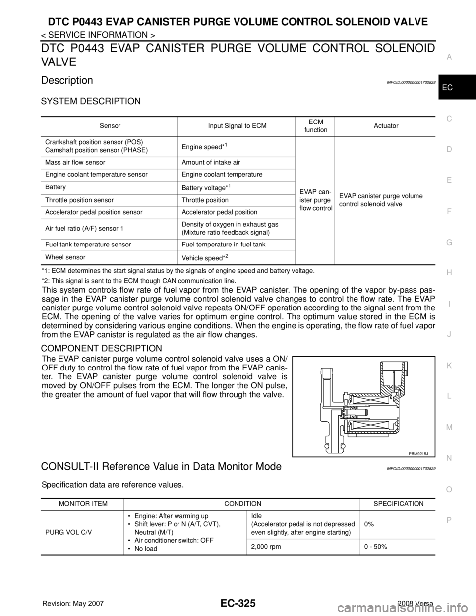
COMPONENT DESCRIPTION
The EVAP canister purge volume control solenoid valve uses a ON/
OFF duty to control the flow rate of fuel vapor from the EVAP canis-
ter. The EVAP canister purge volume control solenoid valve is
moved by ON/OFF pulses from the ECM. The longer the ON pulse,
the greater the amount of fuel vapor that will flow through the valve.
CONSULT-II Reference Value in Data Monitor ModeINFOID:0000000001702829
Specification data are reference values.
Sensor Input Signal to ECMECM
functionActuator
Crankshaft position sensor (POS)
Camshaft position sensor (PHASE)Engine speed*
1
EVAP can-
ister purge
flow controlEVAP canister purge volume
control solenoid valve Mass air flow sensor Amount of intake air
Engine coolant temperature sensor Engine coolant temperature
Battery
Battery voltage*1
Throttle position sensor Throttle position
Accelerator pedal position sensor Accelerator pedal position
Air fuel ratio (A/F) sensor 1Density of oxygen in exhaust gas
(Mixture ratio feedback signal)
Fuel tank temperature sensor Fuel temperature in fuel tank
Wheel sensor
Vehicle speed*
2
PBIA9215J
MONITOR ITEM CONDITION SPECIFICATION
PURG VOL C/V• Engine: After warming up
• Shift lever: P or N (A/T, CVT),
Neutral (M/T)
• Air conditioner switch: OFF
•No loadIdle
(Accelerator pedal is not depressed
even slightly, after engine starting)0%
2,000 rpm 0 - 50%
Page 1402 of 2771
EC-328
< SERVICE INFORMATION >
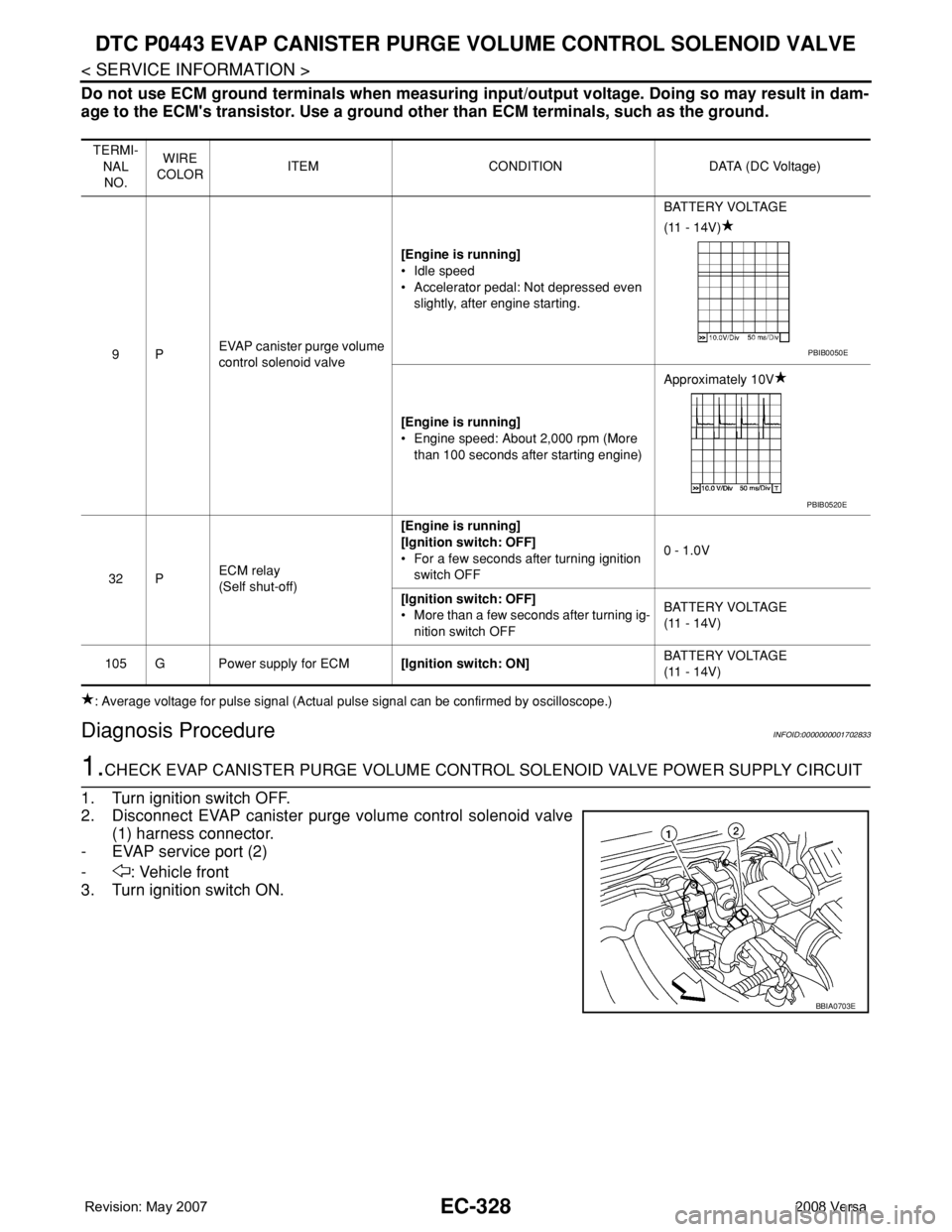
DTC P0443 EVAP CANISTER PURGE VOLUME CONTROL SOLENOID VALVE
Do not use ECM ground terminals when measuring input/output voltage. Doing so may result in dam-
age to the ECM's transistor. Use a ground other than ECM terminals, such as the ground.
: Average voltage for pulse signal (Actual pulse signal can be confirmed by oscilloscope.)
Diagnosis ProcedureINFOID:0000000001702833
1.CHECK EVAP CANISTER PURGE VOLUME CONTROL SOLENOID VALVE POWER SUPPLY CIRCUIT
1. Turn ignition switch OFF.
2. Disconnect EVAP canister purge volume control solenoid valve
(1) harness connector.
- EVAP service port (2)
- : Vehicle front
3. Turn ignition switch ON.
TERMI-
NAL
NO.WIRE
COLORITEM CONDITION DATA (DC Voltage)
9PEVAP canister purge volume
control solenoid valve[Engine is running]
• Idle speed
• Accelerator pedal: Not depressed even
slightly, after engine starting.BATTERY VOLTAGE
(11 - 14V)
[Engine is running]
• Engine speed: About 2,000 rpm (More
than 100 seconds after starting engine)Approximately 10V
32 PECM relay
(Self shut-off)[Engine is running]
[Ignition switch: OFF]
• For a few seconds after turning ignition
switch OFF0 - 1.0V
[Ignition switch: OFF]
• More than a few seconds after turning ig-
nition switch OFFBATTERY VOLTAGE
(11 - 14V)
105 G Power supply for ECM[Ignition switch: ON]BATTERY VOLTAGE
(11 - 14V)
PBIB0050E
PBIB0520E
BBIA0703E
Page 1406 of 2771
EC-332
< SERVICE INFORMATION >
DTC P0444, P0445 EVAP CANISTER PURGE VOLUME CONTROL SOLENOID
VALVE
DTC P0444, P0445 EVAP CANISTER PURGE VOLUME CONTROL SOLE-
NOID VALVE
DescriptionINFOID:0000000001702836
SYSTEM DESCRIPTION
*1: The ECM determines the start signal status by the signal of engine speed and battery voltage.
*2: This signal is sent to the ECM through CAN communication line.
This system controls flow rate of fuel vapor from the EVAP canister. The opening of the vapor by-pass pas-
sage in the EVAP canister purge volume control solenoid valve changes to control the flow rate. The EVAP
canister purge volume control solenoid valve repeats ON/OFF operation according to the signal sent from the
ECM. The opening of the valve varies for optimum engine control. The optimum value stored in the ECM is
determined by considering various engine conditions. When the engine is operating, the flow rate of fuel vapor
from the EVAP canister is regulated as the air flow changes.
COMPONENT DESCRIPTION
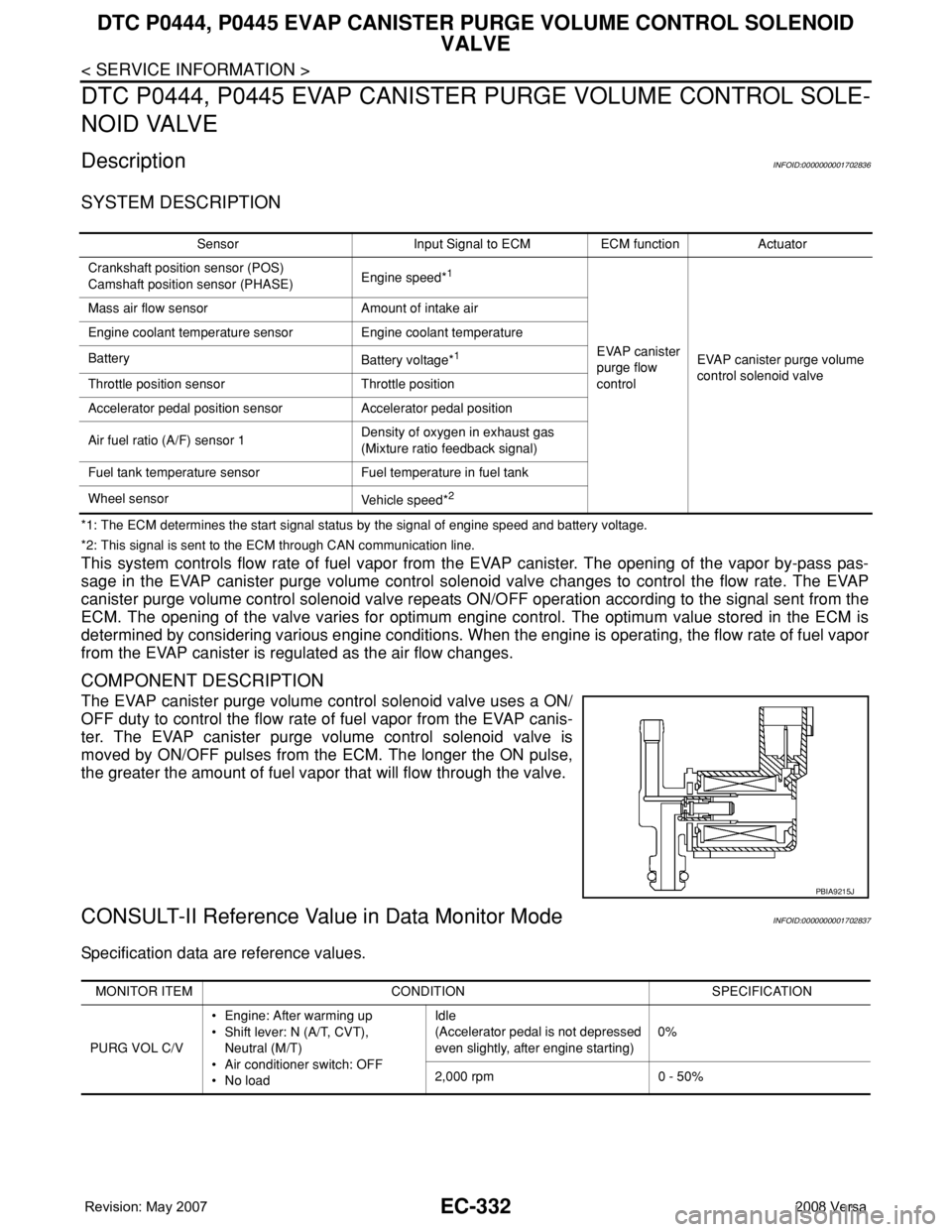
The EVAP canister purge volume control solenoid valve uses a ON/
OFF duty to control the flow rate of fuel vapor from the EVAP canis-
ter. The EVAP canister purge volume control solenoid valve is
moved by ON/OFF pulses from the ECM. The longer the ON pulse,
the greater the amount of fuel vapor that will flow through the valve.
CONSULT-II Reference Value in Data Monitor ModeINFOID:0000000001702837
Specification data are reference values.
Sensor Input Signal to ECM ECM function Actuator
Crankshaft position sensor (POS)
Camshaft position sensor (PHASE)Engine speed*
1
EVAP canister
purge flow
controlEVAP canister purge volume
control solenoid valve Mass air flow sensor Amount of intake air
Engine coolant temperature sensor Engine coolant temperature
Battery
Battery voltage*1
Throttle position sensor Throttle position
Accelerator pedal position sensor Accelerator pedal position
Air fuel ratio (A/F) sensor 1Density of oxygen in exhaust gas
(Mixture ratio feedback signal)
Fuel tank temperature sensor Fuel temperature in fuel tank
Wheel sensor
Vehicle speed*
2
PBIA9215J
MONITOR ITEM CONDITION SPECIFICATION
PURG VOL C/V• Engine: After warming up
• Shift lever: N (A/T, CVT),
Neutral (M/T)
• Air conditioner switch: OFF
• No loadIdle
(Accelerator pedal is not depressed
even slightly, after engine starting)0%
2,000 rpm 0 - 50%