Engine Control System NISSAN TIIDA 2008 Service Repair Manual
[x] Cancel search | Manufacturer: NISSAN, Model Year: 2008, Model line: TIIDA, Model: NISSAN TIIDA 2008Pages: 2771, PDF Size: 60.61 MB
Page 1600 of 2771
EC-526
< SERVICE INFORMATION >
FUEL PUMP
FUEL PUMP
DescriptionINFOID:0000000001703065
SYSTEM DESCRIPTION
*: ECM determines the start signal status by the signals of engine speed and battery voltage.
The ECM activates the fuel pump for several seconds after the ignition switch is turned ON to improve engine
startability. If the ECM receives a engine speed signal from the crankshaft position sensor (POS) and cam-
shaft position sensor (PHASE), it knows that the engine is rotating, and causes the pump to operate. If the
engine speed signal is not received when the ignition switch is ON, the engine stalls. The ECM stops pump
operation and prevents battery discharging, thereby improving safety. The ECM does not directly drive the fuel
pump. It controls the ON/OFF fuel pump relay, which in turn controls the fuel pump.
COMPONENT DESCRIPTION
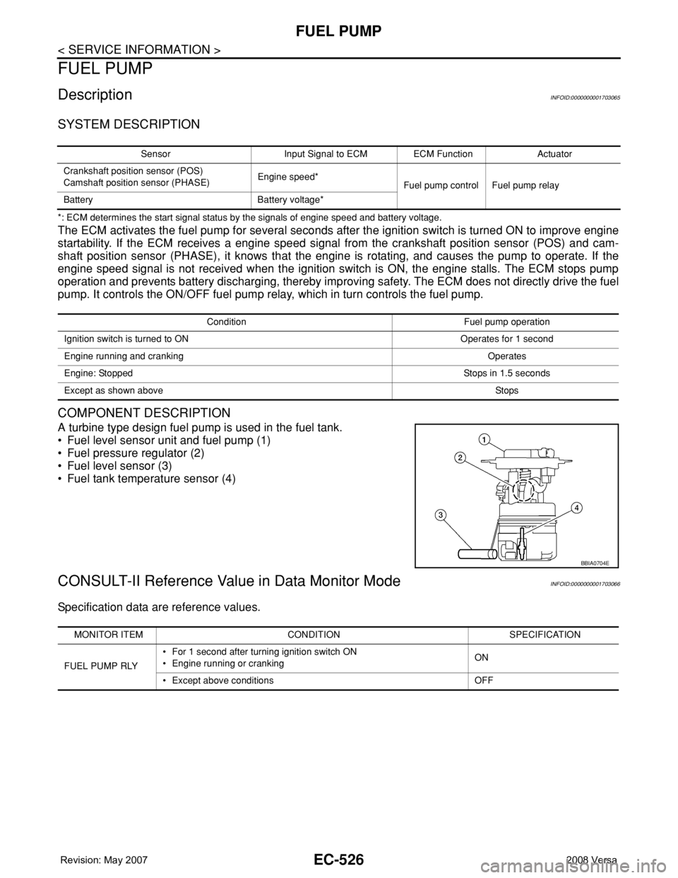
A turbine type design fuel pump is used in the fuel tank.
• Fuel level sensor unit and fuel pump (1)
• Fuel pressure regulator (2)
• Fuel level sensor (3)
• Fuel tank temperature sensor (4)
CONSULT-II Reference Value in Data Monitor ModeINFOID:0000000001703066
Specification data are reference values.
Sensor Input Signal to ECM ECM Function Actuator
Crankshaft position sensor (POS)
Camshaft position sensor (PHASE)Engine speed*
Fuel pump control Fuel pump relay
Battery Battery voltage*
Condition Fuel pump operation
Ignition switch is turned to ON Operates for 1 second
Engine running and crankingOperates
Engine: StoppedStops in 1.5 seconds
Except as shown aboveSt ops
BBIA0704E
MONITOR ITEM CONDITION SPECIFICATION
FUEL PUMP RLY• For 1 second after turning ignition switch ON
• Engine running or crankingON
• Except above conditions OFF
Page 1681 of 2771

EM-4
< SERVICE INFORMATION >
PRECAUTIONS
2. Use the Intelligent Key or mechanical key to turn the ignition switch to the ″ACC″ position. At this time, the
steering lock will be released.
3. Disconnect both battery cables. The steering lock will remain released and the steering wheel can be
rotated.
4. Perform the necessary repair operation.
5. When the repair work is completed, return the ignition switch to the ″LOCK″ position before connecting
the battery cables. (At this time, the steering lock mechanism will engage.)
6. Perform a self-diagnosis check of all control units using CONSULT-III.
Precaution for Drain CoolantINFOID:0000000001702463
• Drain coolant when engine is cooled.
Precaution for Disconnecting Fuel PipingINFOID:0000000001702464
• Before starting work, make sure no fire or spark producing items are in the work area.
• Release fuel pressure before disassembly.
• After disconnecting pipes, plug openings to stop fuel leakage.
Precaution for Removal and DisassemblyINFOID:0000000001702465
• When instructed to use special service tools, use the specified tools. Always be careful to work safely, avoid
forceful or uninstructed operations.
• Exercise maximum care to avoid damage to mating or sliding surfaces.
• Cover openings of engine system with tape or the equivalent, if necessary, to seal out foreign materials.
• Mark and arrange disassembly parts in an organized way for easy troubleshooting and assembly.
• When loosening nuts and bolts, as a basic rule, start with the one furthest outside, then the one diagonally
opposite, and so on. If the order of loosening is specified, do exactly as specified. Power tools may be used
where noted in the step.
Precaution for Inspection, Repair and ReplacementINFOID:0000000001702466
• Before repairing or replacing, thoroughly inspect parts. Inspect new replacement parts in the same way, and
replace if necessary.
Precaution for Assembly and InstallationINFOID:0000000001702467
• Use torque wrench to tighten bolts or nuts to specification.
• When tightening nuts and bolts, as a basic rule, equally tighten in several different steps starting with the
ones in center, then ones on inside and outside diagonally in this order. If the order of tightening is specified,
do exactly as specified.
• Replace with new gasket, packing, oil seal or O-ring.
• Thoroughly wash, clean, and air-blow each part. Carefully check oil or coolant passages for any restriction
and blockage.
• Avoid damaging sliding or mating surfaces. Completely remove foreign materials such as cloth lint or dust.
Before assembly, oil sliding surfaces well.
• Release air within route after draining coolant.
• Before starting engine, apply fuel pressure to fuel lines with turning ignition switch ON (with engine stopped).
Then make sure that there are no leaks at fuel line connections.
• After repairing, start engine and increase engine speed to check coolant, fuel, oil, and exhaust systems for
leakage.
Parts Requiring Angular TighteningINFOID:0000000001702468
• Use an angle wrench for the final tightening of the following engine parts:
- Cylinder head bolts
- Camshaft sprocket (INT)
- Main bearing cap bolts
- Connecting rod cap nuts
- Crankshaft pulley bolt (No angle wrench is required as the bolt flange is provided with notches for angular
tightening)
Page 1731 of 2771
EM-54
< SERVICE INFORMATION >
CAMSHAFT
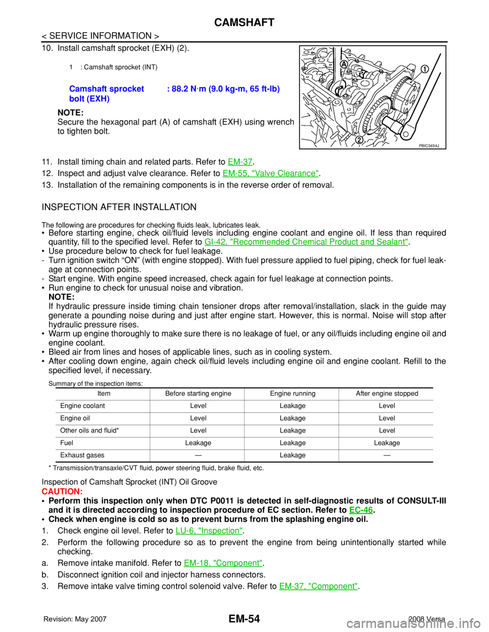
10. Install camshaft sprocket (EXH) (2).
NOTE:
Secure the hexagonal part (A) of camshaft (EXH) using wrench
to tighten bolt.
11. Install timing chain and related parts. Refer to EM-37
.
12. Inspect and adjust valve clearance. Refer to EM-55, "
Valve Clearance".
13. Installation of the remaining components is in the reverse order of removal.
INSPECTION AFTER INSTALLATION
The following are procedures for checking fluids leak, lubricates leak.
• Before starting engine, check oil/fluid levels including engine coolant and engine oil. If less than required
quantity, fill to the specified level. Refer to GI-42, "
Recommended Chemical Product and Sealant".
• Use procedure below to check for fuel leakage.
- Turn ignition switch “ON” (with engine stopped). With fuel pressure applied to fuel piping, check for fuel leak-
age at connection points.
- Start engine. With engine speed increased, check again for fuel leakage at connection points.
• Run engine to check for unusual noise and vibration.
NOTE:
If hydraulic pressure inside timing chain tensioner drops after removal/installation, slack in the guide may
generate a pounding noise during and just after engine start. However, this is normal. Noise will stop after
hydraulic pressure rises.
• Warm up engine thoroughly to make sure there is no leakage of fuel, or any oil/fluids including engine oil and
engine coolant.
• Bleed air from lines and hoses of applicable lines, such as in cooling system.
• After cooling down engine, again check oil/fluid levels including engine oil and engine coolant. Refill to the
specified level, if necessary.
Summary of the inspection items:
* Transmission/transaxle/CVT fluid, power steering fluid, brake fluid, etc.
Inspection of Camshaft Sprocket (INT) Oil Groove
CAUTION:
• Perform this inspection only when DTC P0011 is detected in self-diagnostic results of CONSULT-III
and it is directed according to inspection procedure of EC section. Refer to EC-46
.
• Check when engine is cold so as to prevent burns from the splashing engine oil.
1. Check engine oil level. Refer to LU-6, "
Inspection".
2. Perform the following procedure so as to prevent the engine from being unintentionally started while
checking.
a. Remove intake manifold. Refer to EM-18, "
Component".
b. Disconnect ignition coil and injector harness connectors.
3. Remove intake valve timing control solenoid valve. Refer to EM-37, "
Component".
1 : Camshaft sprocket (INT)
Camshaft sprocket
bolt (EXH): 88.2 N·m (9.0 kg-m, 65 ft-lb)
PBIC3454J
Item Before starting engine Engine running After engine stopped
Engine coolant Level Leakage Level
Engine oil Level Leakage Level
Other oils and fluid* Level Leakage Level
Fuel Leakage Leakage Leakage
Exhaust gases — Leakage —
Page 1852 of 2771

GI-1
GENERAL INFORMATION
C
D
E
F
G
H
I
J
K
L
MB
GI
SECTION GI
N
O
P
CONTENTS
GENERAL INFORMATION
SERVICE INFORMATION ............................2
PRECAUTIONS ...................................................2
Description ................................................................2
Precaution for Supplemental Restraint System
(SRS) "AIR BAG" and "SEAT BELT PRE-TEN-
SIONER" ...................................................................
2
Precaution Necessary for Steering Wheel Rota-
tion After Battery Disconnect .....................................
2
General Precaution ...................................................3
Precaution for Three Way Catalyst ...........................4
Precaution for Fuel (Unleaded Regular Gasoline
Recommended) .........................................................
4
Precaution for Multiport Fuel Injection System or
Engine Control System .............................................
5
Precaution for Hoses .................................................5
Precaution for Engine Oils ........................................6
Precaution for Air Conditioning .................................6
HOW TO USE THIS MANUAL ............................7
Description ................................................................7
Terms ........................................................................7
Units ..........................................................................7
Contents ....................................................................7
Relation between Illustrations and Descriptions .......8
Component ................................................................8
How to Follow Trouble Diagnosis ..............................9
How to Read Wiring Diagram ..................................13
Abbreviations ..........................................................20
SERVICE INFORMATION FOR ELECTRICAL
INCIDENT ...........................................................
22
How to Check Terminal ...........................................22
How to Perform Efficient Diagnosis for an Electri-
cal Incident ..............................................................
25
Control Units and Electrical Parts ............................32
CONSULT-III CHECKING SYSTEM .................35
Description ...............................................................35
Function and System Application ............................35
CONSULT-III Data Link Connector (DLC) Circuit ....36
LIFTING POINT .................................................38
Special Service Tool ................................................38
Garage Jack and Safety Stand and 2-Pole Lift .......38
Board-On Lift ...........................................................39
TOW TRUCK TOWING .....................................40
Tow Truck Towing ...................................................40
Vehicle Recovery (Freeing a Stuck Vehicle) ...........40
TIGHTENING TORQUE OF STANDARD
BOLTS ...............................................................
41
Tightening Torque Table .........................................41
RECOMMENDED CHEMICAL PRODUCTS
AND SEALANTS ...............................................
42
Recommended Chemical Product and Sealant .......42
IDENTIFICATION INFORMATION ....................43
Model Variation ........................................................43
Dimensions ..............................................................46
Wheels & Tires ........................................................46
TERMINOLOGY ................................................47
SAE J1930 Terminology List ...................................47
Page 1855 of 2771
GI-4
< SERVICE INFORMATION >
PRECAUTIONS
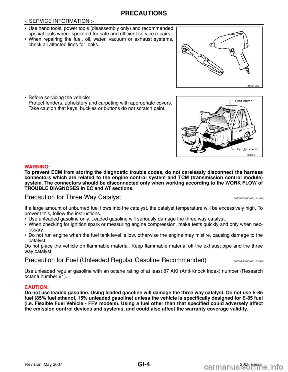
• Use hand tools, power tools (disassembly only) and recommended
special tools where specified for safe and efficient service repairs.
• When repairing the fuel, oil, water, vacuum or exhaust systems,
check all affected lines for leaks.
• Before servicing the vehicle:
Protect fenders, upholstery and carpeting with appropriate covers.
Take caution that keys, buckles or buttons do not scratch paint.
WARNING:
To prevent ECM from storing the diagnostic trouble codes, do not carelessly disconnect the harness
connectors which are related to the engine control system and TCM (transmission control module)
system. The connectors should be disconnected only when working according to the WORK FLOW of
TROUBLE DIAGNOSES in EC and AT sections.
Precaution for Three Way CatalystINFOID:0000000001702425
If a large amount of unburned fuel flows into the catalyst, the catalyst temperature will be excessively high. To
prevent this, follow the instructions.
• Use unleaded gasoline only. Leaded gasoline will seriously damage the three way catalyst.
• When checking for ignition spark or measuring engine compression, make tests quickly and only when nec-
essary.
• Do not run engine when the fuel tank level is low, otherwise the engine may misfire, causing damage to the
catalyst.
Do not place the vehicle on flammable material. Keep flammable material off the exhaust pipe and the three
way catalyst.
Precaution for Fuel (Unleaded Regular Gasoline Recommended)INFOID:0000000001702426
Use unleaded regular gasoline with an octane rating of at least 87 AKI (Anti-Knock Index) number (Research
octane number 91).
CAUTION:
Do not use leaded gasoline. Using leaded gasoline will damage the three way catalyst. Do not use E-85
fuel (85% fuel ethanol, 15% unleaded gasoline) unless the vehicle is specifically designed for E-85 fuel
(i.e. Flexible Fuel Vehicle - FFV models). Using a fuel other than that specified could adversely affect
the emission control devices and systems, and could also affect the warranty coverage validity.
PBIC0190E
SGI234
Page 1856 of 2771
PRECAUTIONS
GI-5
< SERVICE INFORMATION >
C
D
E
F
G
H
I
J
K
L
MB
GI
N
O
P
Precaution for Multiport Fuel Injection System or Engine Control SystemINFOID:0000000001702427
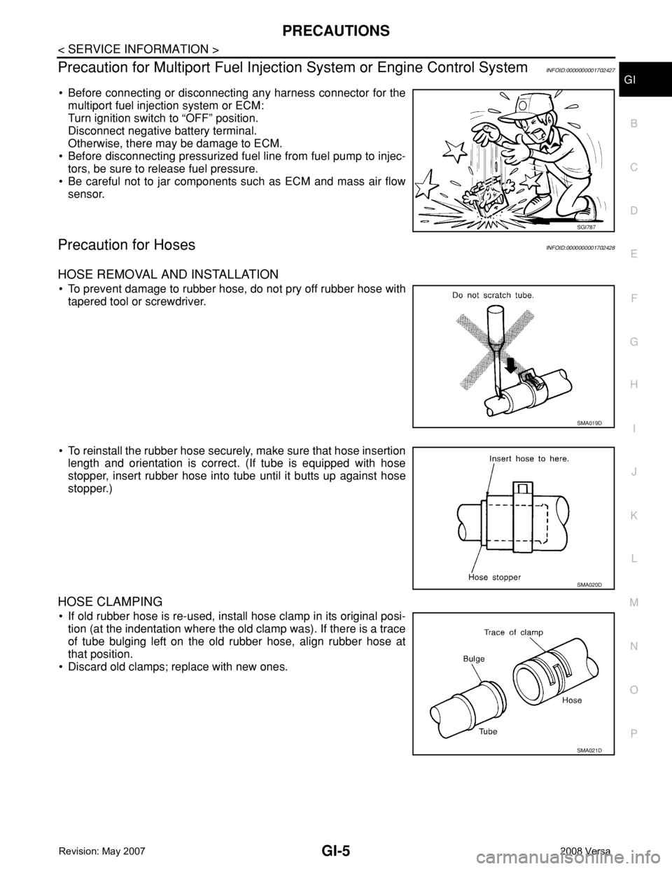
• Before connecting or disconnecting any harness connector for the
multiport fuel injection system or ECM:
Turn ignition switch to “OFF” position.
Disconnect negative battery terminal.
Otherwise, there may be damage to ECM.
• Before disconnecting pressurized fuel line from fuel pump to injec-
tors, be sure to release fuel pressure.
• Be careful not to jar components such as ECM and mass air flow
sensor.
Precaution for HosesINFOID:0000000001702428
HOSE REMOVAL AND INSTALLATION
• To prevent damage to rubber hose, do not pry off rubber hose with
tapered tool or screwdriver.
• To reinstall the rubber hose securely, make sure that hose insertion
length and orientation is correct. (If tube is equipped with hose
stopper, insert rubber hose into tube until it butts up against hose
stopper.)
HOSE CLAMPING
• If old rubber hose is re-used, install hose clamp in its original posi-
tion (at the indentation where the old clamp was). If there is a trace
of tube bulging left on the old rubber hose, align rubber hose at
that position.
• Discard old clamps; replace with new ones.
SGI787
SMA019D
SMA020D
SMA021D
Page 1886 of 2771

CONSULT-III CHECKING SYSTEM
GI-35
< SERVICE INFORMATION >
C
D
E
F
G
H
I
J
K
L
MB
GI
N
O
PCONSULT-III CHECKING SYSTEM
DescriptionINFOID:0000000001806209
• CONSULT-III is a hand-held type tester. When it is connected with a diagnostic connector equipped on the
vehicle side, it will communicate with the control unit equipped in the vehicle and then enable various kinds
of diagnostic tests.
• Refer to CONSULT-III Operator's Manual for more information.
Function and System ApplicationINFOID:0000000001806219
x: Applicable.
*1: If equipped.
*2: This option is shown on vehicles equipped with continuously variable transmission (CVT).
*3: NVIS (NATS) [NISSAN Vehicle Immobilizer System (Nissan Anti-theft System)]. Diagnostic test mode Function
ENGINE
ABS*
1
AIR BAG
EPS
IPDM E/R
BCM
METER/M&A
INTELLIGENT KEY*
1
A/T*
1
TRANSMISSION*
2
NVIS (NATS)*
3
NVIS (NATS BCM OR S/ENT)*
3
NATS I-KEY
*3,5
Work supportThis mode enables a technician to adjust some devices faster
and more accurately by following indications on CONSULT-III.x----x-xxx--x
Self-diagnostic results Self-diagnostic results can be read and erased quickly. xxxxxxxxxxx - x
Trouble diagnostic
recordCurrent self-diagnostic results and all trouble diagnostic records
previously stored can be read.--x----------
Data monitor Input/Output data in the ECU can be read. xx - xx - xxxx - - -
CAN diagnostic support
monitorThe communication condition of CAN communication line can
be read.xx - xxxxxxx - - -
Calibration data*
2Shows unit calibration IDs, offsets and gains. This data is stored
in the ECU memory.---------x---
Active testDiagnostic Test Mode in which CONSULT-III drives actuators
apart from ECU shifting some parameters in a specified range.xx--x--x-----
Function testThis mode can show results of self-diagnosis of ECU with either
"OK" or "NG". For engines, more practical tests regarding sen-
sors/switches and/or actuators are available.xxx-----xx---
DTC & SRT confirmationThe results of SRT (System Readiness Test) and the self-diag-
nosis status/result can be confirmed.x------------
DTC work supportThe operating condition to confirm Diagnosis Trouble Codes
can be selected.x-------x----
ECM/ECU part number ECM/ECU part number can be read. x x - x - x - x x x - - -
ECU discriminated No.Classification number of a replacement ECU can be read to pre-
vent an incorrect ECU from being installed.--x----------
Passenger airbag Displays the STATUS (readiness) of front passenger air bag. --x----------
Configuration Sets control module parameters to match vehicle options. -----x-------
Steering lock release
*4,5Condition of steering lock release solenoid. -----------x-
Control unit initializa-
tion
*4,6All registered ignition key IDs in NATS components can be ini-
tialized and new IDs can be registered.----------x--
PIN Read
*4This mode enables technician to get BCM-specific 5-digit code.-----------x-
Page 1895 of 2771
GI-44
< SERVICE INFORMATION >
IDENTIFICATION INFORMATION
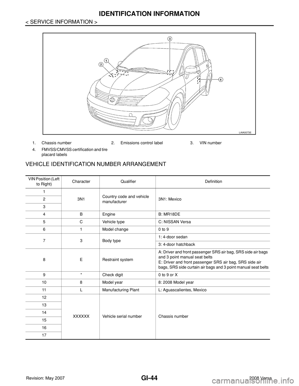
VEHICLE IDENTIFICATION NUMBER ARRANGEMENT
1. Chassis number 2. Emissions control label 3. VIN number
4. FMVSS/CMVSS certification and tire
placard labels
LAIA0073E
VIN Position (Left
to Right)Character Qualifier Definition
1
3N1Country code and vehicle
manufacturer3N1: Mexico 2
3
4 B Engine B: MR18DE
5 C Vehicle type C: NISSAN Versa
6 1 Model change 0 to 9
7 3 Body type1: 4-door sedan
3: 4-door hatchback
8 E Restraint systemA: Driver and front passenger SRS air bag, SRS side air bags
and 3 point manual seat belts
E: Driver and front passenger SRS air bag, SRS side air
bags, SRS side curtain air bags and 3 point manual seat belts
9 * Check digit 0 to 9 or X
10 8 Model year 8: 2008 Model year
11 L Manufacturing Plant L: Aguascalientes, Mexico
12
XXXXXX Vehicle serial number Chassis number 13
14
15
16
17
Page 1898 of 2771

TERMINOLOGY
GI-47
< SERVICE INFORMATION >
C
D
E
F
G
H
I
J
K
L
MB
GI
N
O
PTERMINOLOGY
SAE J1930 Terminology ListINFOID:0000000001702459
All emission related terms used in this publication in accordance with SAE J1930 are listed. Accordingly, new
terms, new acronyms/abbreviations and old terms are listed in the following chart.
NEW TERMNEW ACRONYM /
ABBREVIATIONOLD TERM
Air cleaner ACL Air cleaner
Barometric pressure BARO ***
Barometric pressure sensor-BCDD BAROS-BCDD BCDD
Camshaft position CMP ***
Camshaft position sensor CMPS Crank angle sensor
Canister *** Canister
Carburetor CARB Carburetor
Charge air cooler CAC Intercooler
Closed loop CL Closed loop
Closed throttle position switch CTP switch Idle switch
Clutch pedal position switch CPP switch Clutch switch
Continuous fuel injection system CFI system ***
Continuous trap oxidizer system CTOX system ***
Crankshaft position CKP ***
Crankshaft position sensor CKPS ***
Data link connector DLC ***
Data link connector for CONSULT-III DLC for CONSULT-III Diagnostic connector for CONSULT-III
Diagnostic test mode DTM Diagnostic mode
Diagnostic test mode selector DTM selector Diagnostic mode selector
Diagnostic test mode I DTM I Mode I
Diagnostic test mode II DTM II Mode II
Diagnostic trouble code DTC Malfunction code
Direct fuel injection system DFI system ***
Distributor ignition system DI system Ignition timing control
Early fuel evaporation-mixture heater EFE-mixture heater Mixture heater
Early fuel evaporation system EFE system Mixture heater control
Electrically erasable programmable read
only memoryEEPROM ***
Electronic ignition system EI system Ignition timing control
Engine control EC ***
Engine control module ECM ECCS control unit
Engine coolant temperature ECT Engine temperature
Engine coolant temperature sensor ECTS Engine temperature sensor
Engine modification EM ***
Engine speed RPM Engine speed
Erasable programmable read only memory EPROM ***
Evaporative emission canister EVAP canister Canister
Evaporative emission system EVAP system Canister control solenoid valve
Exhaust gas recirculation valve EGR valve EGR valve
Page 1899 of 2771

GI-48
< SERVICE INFORMATION >
TERMINOLOGY
Exhaust gas recirculation control-BPT
valveEGRC-BPT valve BPT valve
Exhaust gas recirculation control-solenoid
valveEGRC-solenoid valve EGR control solenoid valve
Exhaust gas recirculation temperature sen-
sor
EGRT sensor Exhaust gas temperature sensor
EGR temperature sensor
Flash electrically erasable programmable
read only memoryFEEPROM ***
Flash erasable programmable read only
memoryFEPROM ***
Flexible fuel sensor FFS ***
Flexible fuel system FF system ***
Fuel pressure regulator *** Pressure regulator
Fuel pressure regulator control solenoid
valve*** PRVR control solenoid valve
Fuel trim FT ***
Heated Oxygen sensor HO2S Exhaust gas sensor
Idle air control system IAC system Idle speed control
Idle air control valve-air regulator IACV-air regulator Air regulator
Idle air control valve-auxiliary air control
valveIACV-AAC valve Auxiliary air control (AAC) valve
Idle air control valve-FICD solenoid valve IACV-FICD solenoid valve FICD solenoid valve
Idle air control valve-idle up control sole-
noid valveIACV-idle up control solenoid valve Idle up control solenoid valve
Idle speed control-FI pot ISC-FI pot FI pot
Idle speed control system ISC system ***
Ignition control IC ***
Ignition control module ICM ***
Indirect fuel injection system IFI system ***
Intake air IA Air
Intake air temperature sensor IAT sensor Air temperature sensor
Knock *** Detonation
Knock sensor KS Detonation sensor
Malfunction indicator lamp MIL Check engine light
Manifold absolute pressure MAP ***
Manifold absolute pressure sensor MAPS ***
Manifold differential pressure MDP ***
Manifold differential pressure sensor MDPS ***
Manifold surface temperature MST ***
Manifold surface temperature sensor MSTS ***
Manifold vacuum zone MVZ ***
Manifold vacuum zone sensor MVZS ***
Mass air flow sensor MAFS Air flow meter
Mixture control solenoid valve MC solenoid valve Air-fuel ratio control solenoid valve
Multiport fuel injection System MFI system Fuel injection controlNEW TERMNEW ACRONYM /
ABBREVIATIONOLD TERM