Engine Control System NISSAN TIIDA 2008 Service Repair Manual
[x] Cancel search | Manufacturer: NISSAN, Model Year: 2008, Model line: TIIDA, Model: NISSAN TIIDA 2008Pages: 2771, PDF Size: 60.61 MB
Page 2387 of 2771
TROUBLE DIAGNOSIS
MTC-49
< SERVICE INFORMATION >
C
D
E
F
G
H
I
K
L
MA
B
MTC
N
O
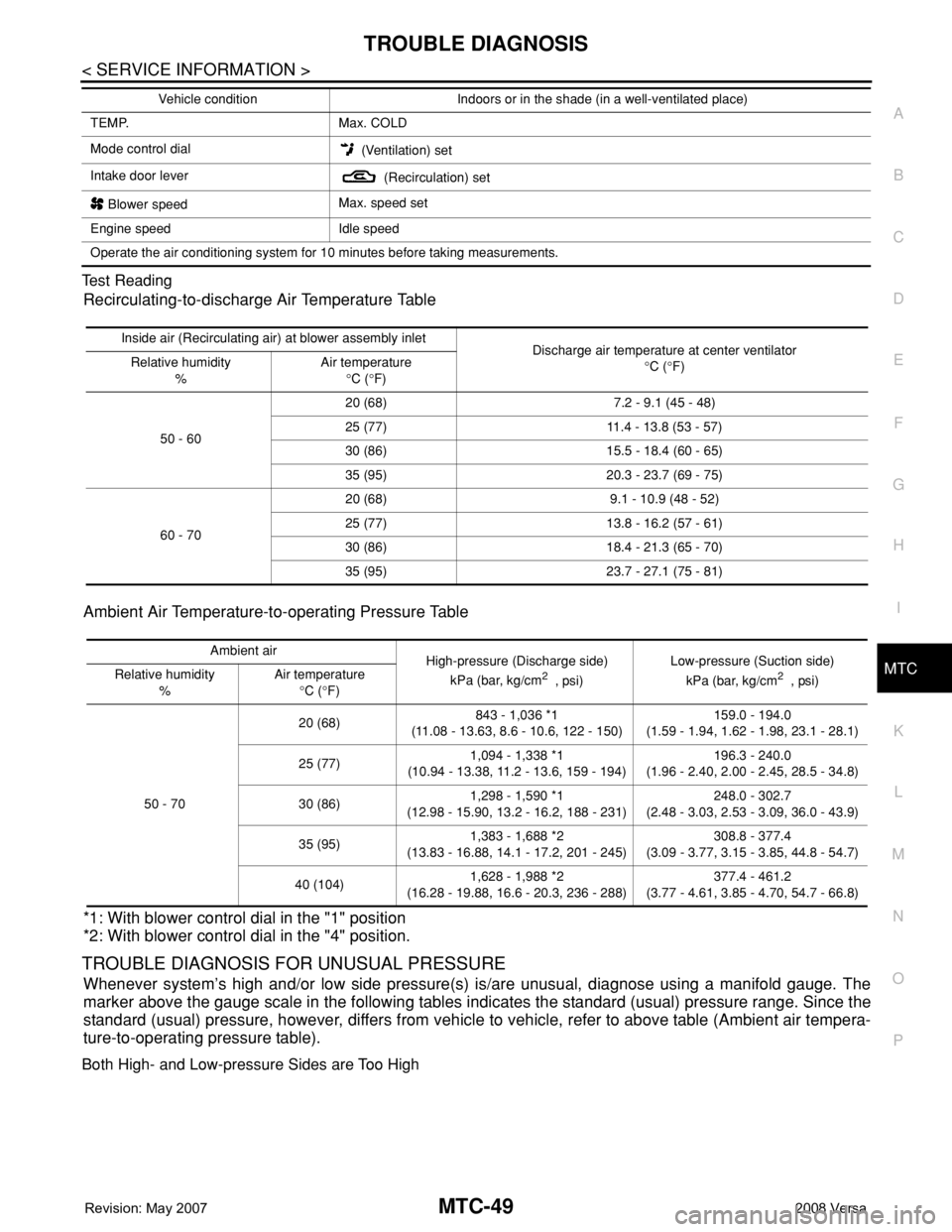
P Test Reading
Recirculating-to-discharge Air Temperature Table
Ambient Air Temperature-to-operating Pressure Table
*1: With blower control dial in the "1" position
*2: With blower control dial in the "4" position.
TROUBLE DIAGNOSIS FOR UNUSUAL PRESSURE
Whenever system’s high and/or low side pressure(s) is/are unusual, diagnose using a manifold gauge. The
marker above the gauge scale in the following tables indicates the standard (usual) pressure range. Since the
standard (usual) pressure, however, differs from vehicle to vehicle, refer to above table (Ambient air tempera-
ture-to-operating pressure table).
Both High- and Low-pressure Sides are Too High
TEMP. Max. COLD
Mode control dial
(Ventilation) set
Intake door lever
(Recirculation) set
Blower speedMax. speed set
Engine speed Idle speed
Operate the air conditioning system for 10 minutes before taking measurements.Vehicle condition Indoors or in the shade (in a well-ventilated place)
Inside air (Recirculating air) at blower assembly inlet
Discharge air temperature at center ventilator
°C (°F) Relative humidity
%Air temperature
°C (°F)
50 - 6020 (68) 7.2 - 9.1 (45 - 48)
25 (77) 11.4 - 13.8 (53 - 57)
30 (86) 15.5 - 18.4 (60 - 65)
35 (95) 20.3 - 23.7 (69 - 75)
60 - 7020 (68) 9.1 - 10.9 (48 - 52)
25 (77) 13.8 - 16.2 (57 - 61)
30 (86) 18.4 - 21.3 (65 - 70)
35 (95) 23.7 - 27.1 (75 - 81)
Ambient air
High-pressure (Discharge side)
kPa (bar, kg/cm
2 , psi)Low-pressure (Suction side)
kPa (bar, kg/cm2 , psi) Relative humidity
%Air temperature
°C (°F)
50 - 7020 (68)843 - 1,036 *1
(11.08 - 13.63, 8.6 - 10.6, 122 - 150)159.0 - 194.0
(1.59 - 1.94, 1.62 - 1.98, 23.1 - 28.1)
25 (77)1,094 - 1,338 *1
(10.94 - 13.38, 11.2 - 13.6, 159 - 194)196.3 - 240.0
(1.96 - 2.40, 2.00 - 2.45, 28.5 - 34.8)
30 (86)1,298 - 1,590 *1
(12.98 - 15.90, 13.2 - 16.2, 188 - 231)248.0 - 302.7
(2.48 - 3.03, 2.53 - 3.09, 36.0 - 43.9)
35 (95)1,383 - 1,688 *2
(13.83 - 16.88, 14.1 - 17.2, 201 - 245)308.8 - 377.4
(3.09 - 3.77, 3.15 - 3.85, 44.8 - 54.7)
40 (104)1,628 - 1,988 *2
(16.28 - 19.88, 16.6 - 20.3, 236 - 288)377.4 - 461.2
(3.77 - 4.61, 3.85 - 4.70, 54.7 - 66.8)
Page 2390 of 2771
MTC-52
< SERVICE INFORMATION >
TROUBLE DIAGNOSIS
Insufficient Heating
INFOID:0000000001704307
SYMPTOM: Insufficient heating
INSPECTION FLOW
1.CONFIRM SYMPTOM BY PERFORMING OPERATIONAL CHECK - TEMPERATURE DECREASE
1. Turn temperature control dial clockwise to maximum heat position.
2. Check for hot air at discharge air outlets.
Can the symptom be duplicated?
YES >> GO TO 3.
NO >> GO TO 2.
2.CHECK FOR ANY SYMPTOMS
Perform a complete operational check for any symptoms. Refer to MTC-30, "
Operational Check" .
Does another symptom exist?
YES >> Refer to MTC-22, "How to Perform Trouble Diagnosis for Quick and Accurate Repair" .
NO >> System OK.
3.CHECK FOR SERVICE BULLETINS
Check for any service bulletins.
>> GO TO 4.
4.CHECK COOLANT SYSTEM
1. Check engine coolant level. Refer to CO-8
.
2. Check hoses for leaks or kinks.
3. Check Radiator cap. Refer to CO-13, "
Checking Radiator Cap" .
OK or NG
OK >> GO TO 5.
NG >> Repair/replace as necessary.
5.CHECK AIR MIX DOOR CABLE
Check air mix door cable operation. Refer to MTC-64, "
Air Mix Door Cable Adjustment" .
OK or NG
YES >> GO TO 6.
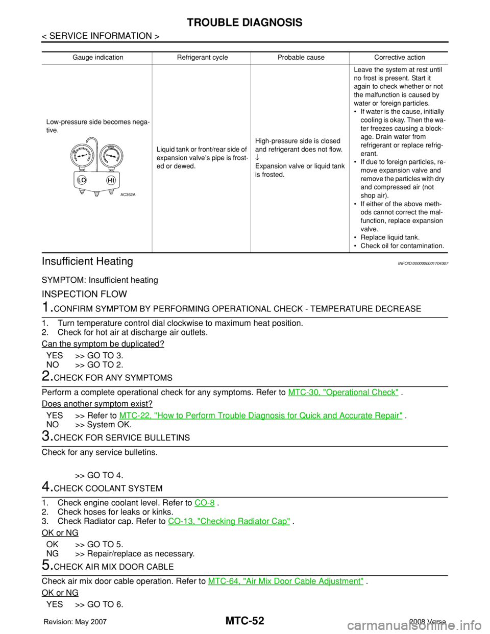
Gauge indication Refrigerant cycle Probable cause Corrective action
Low-pressure side becomes nega-
tive.
Liquid tank or front/rear side of
expansion valve’s pipe is frost-
ed or dewed.High-pressure side is closed
and refrigerant does not flow.
↓
Expansion valve or liquid tank
is frosted.Leave the system at rest until
no frost is present. Start it
again to check whether or not
the malfunction is caused by
water or foreign particles.
• If water is the cause, initially
cooling is okay. Then the wa-
ter freezes causing a block-
age. Drain water from
refrigerant or replace refrig-
erant.
• If due to foreign particles, re-
move expansion valve and
remove the particles with dry
and compressed air (not
shop air).
• If either of the above meth-
ods cannot correct the mal-
function, replace expansion
valve.
• Replace liquid tank.
• Check oil for contamination.
AC362A
Page 2391 of 2771
TROUBLE DIAGNOSIS
MTC-53
< SERVICE INFORMATION >
C
D
E
F
G
H
I
K
L
MA
B
MTC
N
O
P
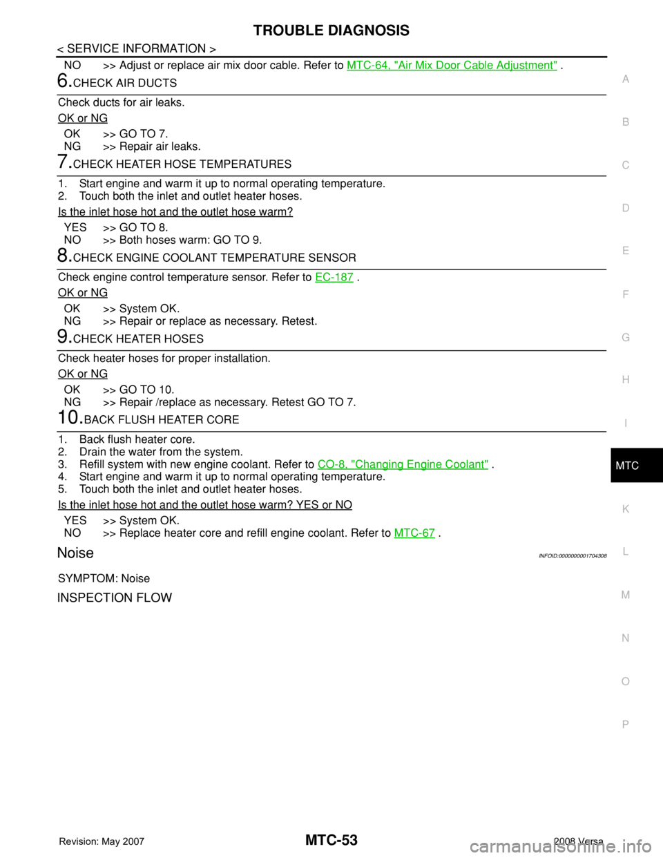
NO >> Adjust or replace air mix door cable. Refer to MTC-64, "Air Mix Door Cable Adjustment" .
6.CHECK AIR DUCTS
Check ducts for air leaks.
OK or NG
OK >> GO TO 7.
NG >> Repair air leaks.
7.CHECK HEATER HOSE TEMPERATURES
1. Start engine and warm it up to normal operating temperature.
2. Touch both the inlet and outlet heater hoses.
Is the inlet hose hot and the outlet hose warm?
YES >> GO TO 8.
NO >> Both hoses warm: GO TO 9.
8.CHECK ENGINE COOLANT TEMPERATURE SENSOR
Check engine control temperature sensor. Refer to EC-187
.
OK or NG
OK >> System OK.
NG >> Repair or replace as necessary. Retest.
9.CHECK HEATER HOSES
Check heater hoses for proper installation.
OK or NG
OK >> GO TO 10.
NG >> Repair /replace as necessary. Retest GO TO 7.
10.BACK FLUSH HEATER CORE
1. Back flush heater core.
2. Drain the water from the system.
3. Refill system with new engine coolant. Refer to CO-8, "
Changing Engine Coolant" .
4. Start engine and warm it up to normal operating temperature.
5. Touch both the inlet and outlet heater hoses.
Is the inlet hose hot and the outlet hose warm? YES or NO
YES >> System OK.
NO >> Replace heater core and refill engine coolant. Refer to MTC-67
.
NoiseINFOID:0000000001704308
SYMPTOM: Noise
INSPECTION FLOW
Page 2397 of 2771
A/C UNIT ASSEMBLY
MTC-59
< SERVICE INFORMATION >
C
D
E
F
G
H
I
K
L
MA
B
MTC
N
O
P
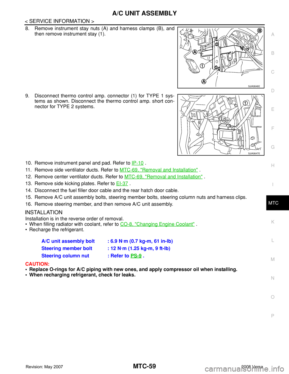
8. Remove instrument stay nuts (A) and harness clamps (B), and
then remove instrument stay (1).
9. Disconnect thermo control amp. connector (1) for TYPE 1 sys-
tems as shown. Disconnect the thermo control amp. short con-
nector for TYPE 2 systems.
10. Remove instrument panel and pad. Refer to IP-10
.
11. Remove side ventilator ducts. Refer to MTC-69, "
Removal and Installation" .
12. Remove center ventilator ducts. Refer to MTC-69, "
Removal and Installation" .
13. Remove side kicking plates. Refer to EI-37
.
14. Disconnect the fuel filler door cable and the rear hatch door cable.
15. Remove A/C unit assembly bolts, steering member bolts, steering column nuts and harness clips.
16. Remove steering member, and then remove A/C unit assembly.
INSTALLATION
Installation is in the reverse order of removal.
• When filling radiator with coolant, refer to CO-8, "
Changing Engine Coolant" .
• Recharge the refrigerant.
CAUTION:
• Replace O-rings for A/C piping with new ones, and apply compressor oil when installing.
• When recharging refrigerant, check for leaks.
SJIA0646E
SJIA0647E
A/C unit assembly bolt : 6.9 N·m (0.7 kg-m, 61 in-lb)
Steering member bolt : 12 N·m (1.25 kg-m, 9 ft-lb)
Steering column nut : Refer to PS-9
.
Page 2425 of 2771
REFRIGERANT LINES
MTC-87
< SERVICE INFORMATION >
C
D
E
F
G
H
I
K
L
MA
B
MTC
N
O
P
Check all around the service valves. Ensure service valve caps are secured on the service valves (to
prevent leaks).
NOTE:
After removing A/C manifold gauge set from service valves, wipe any residue from valves to prevent any
false readings by leak detector.
• Cooling unit (Evaporator)
With engine OFF, turn blower fan on “High” for at least 15 seconds to dissipate any refrigerant trace in
the cooling unit. Wait a minimum of 10 minutes accumulation time (refer to the manufacturer’s recom-
mended procedure for actual wait time) before inserting the leak detector probe into the drain hose.
Keep the probe inserted for at least 10 seconds. Use caution not to contaminate the probe tip with water
or dirt that may be in the drain hose.
5. If a leak detector detects a leak, verify at least once by blowing compressed air into area of suspected
leak, then repeat check as outlined above.
6. Do not stop when one leak is found. Continue to check for additional leaks at all system components.
If no leaks are found, perform steps 7-10.
7. Start engine.
8. Set the heater A/C control as follows;
a. A/C switch: ON
b. Mode control dial position: VENT (Ventilation)
c. Intake door lever position: Recirculation
d. Max. cold temperature
e. Fan speed: High
9. Run engine at 1,500 rpm for at least 2 minutes.
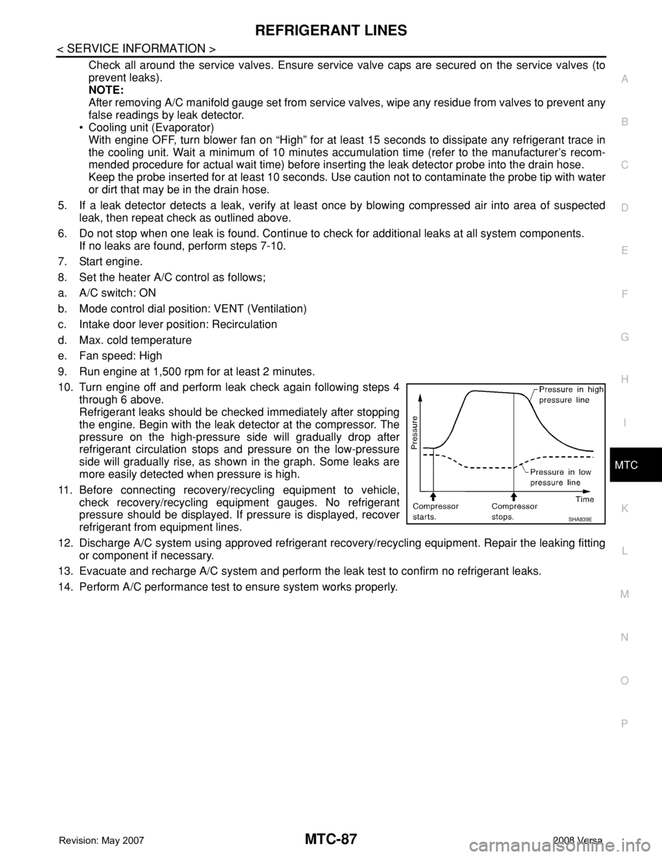
10. Turn engine off and perform leak check again following steps 4
through 6 above.
Refrigerant leaks should be checked immediately after stopping
the engine. Begin with the leak detector at the compressor. The
pressure on the high-pressure side will gradually drop after
refrigerant circulation stops and pressure on the low-pressure
side will gradually rise, as shown in the graph. Some leaks are
more easily detected when pressure is high.
11. Before connecting recovery/recycling equipment to vehicle,
check recovery/recycling equipment gauges. No refrigerant
pressure should be displayed. If pressure is displayed, recover
refrigerant from equipment lines.
12. Discharge A/C system using approved refrigerant recovery/recycling equipment. Repair the leaking fitting
or component if necessary.
13. Evacuate and recharge A/C system and perform the leak test to confirm no refrigerant leaks.
14. Perform A/C performance test to ensure system works properly.
SHA839E
Page 2449 of 2771

PG-16
< SERVICE INFORMATION >
IPDM E/R (INTELLIGENT POWER DISTRIBUTION MODULE ENGINE ROOM)
IPDM E/R (INTELLIGENT POWER DISTRIBUTION MODULE ENGINE
ROOM)
System DescriptionINFOID:0000000001704697
• IPDM E/R (Intelligent Power Distribution Module Engine Room) integrates the relay box and fuse block
which were originally placed in engine compartment. It controls integrated relays via IPDM E/R control cir-
cuits.
• IPDM E/R-integrated control circuits perform ON-OFF operation of relays, CAN communication control, oil
pressure switch signal reception, etc.
• It controls operation of each electrical component via ECM, BCM and CAN communication lines.
CAUTION:
None of the IPDM E/R integrated relays can be removed.
SYSTEMS CONTROLLED BY IPDM E/R
1. Lamp control
Using CAN communication lines, it receives signals from the BCM and controls the following lamps:
• Headlamps (High, Low)
• Parking lamps
• Tail and license plate lamps
• Front fog lamps
2. Wiper control
Using CAN communication lines, it receives signals from the BCM and controls the front wipers.
3. Rear window defogger relay control
Using CAN communication lines, it receives signals from the BCM and controls the rear window defogger
relay.
4. A/C compressor control
Using CAN communication lines, it receives signals from the ECM and controls the A/C compressor
(magnet clutch).
5. Starter control
Using CAN communication lines, it receives signals from the BCM and controls the starter relay.
6. Cooling fan control
Using CAN communication lines, it receives signals from the ECM and controls the cooling fan relays.
7. Horn control
Using CAN communication lines, it receives signals from the BCM and controls the horn relay.
8. Daytime light system control (Canada only)
Using CAN communication lines, it receives signals from the BCM and controls the daytime light relay.
CAN COMMUNICATION LINE CONTROL
With CAN communication, by connecting each control unit using two communication lines (CAN L-line, CAN
H-line), it is possible to transmit a maximum amount of information with minimum wiring. Each control unit can
transmit and receive data, and reads necessary information only.
1. Fail-safe control
• When CAN communication with other control units is impossible, IPDM E/R performs fail-safe control.
After CAN communication returns to normal operation, it also returns to normal control.
• Operation of control parts by IPDM E/R during fail-safe mode is as follows:
Controlled system Fail-safe mode
Headlamp• With the ignition switch ON, headlamp low relay is ON, headlamp high relays are OFF, and
daytime light system (Canada only) is OFF.
• With the ignition switch OFF, the headlamp relays are OFF.
Tail, license plate and parking lamps • With the ignition switch ON, the tail lamp relay is ON.
• With the ignition switch OFF, the tail lamp relay is OFF.
Cooling fan• With the ignition switch ON, cooling fan relay-1, relay-2, and relay-3 are ON.
• With the ignition switch OFF, all cooling fan relays are OFF.
Front wiperUntil the ignition switch is turned off, the front wiper relays remain in the same status they
were in just before fail−safe control was initiated.
Page 2450 of 2771
IPDM E/R (INTELLIGENT POWER DISTRIBUTION MODULE ENGINE ROOM)
PG-17
< SERVICE INFORMATION >
C
D
E
F
G
H
I
J
L
MA
B
PG
N
O
P
IPDM E/R STATUS CONTROL
In order to save power, IPDM E/R switches status by itself based on each operating condition.
1. CAN communication status
• CAN communication is normally performed with other control units.
• Individual unit control by IPDM E/R is normally performed.
• When sleep request signal is received from BCM, mode is switched to sleep waiting status.
2. Sleep waiting status
• Process to stop CAN communication is activated.
• All systems controlled by IPDM E/R are stopped. When 1 second has elapsed after CAN communica-
tion with other control units is stopped, mode switches to sleep status.
3. Sleep status
• IPDM E/R operates in low current-consumption mode.
• CAN communication is stopped.
• When a change in CAN communication signal is detected, mode switches to CAN communication sta-
tus.
• When a change in ignition switch signal is detected, mode switches to CAN communication status.
CAN Communication System DescriptionINFOID:0000000001704698
Refer to LAN-6, "System Description".
Function of Detecting Ignition Relay MalfunctionINFOID:0000000001704699
• When the integrated ignition relay is stuck in a "closed contact" position and cannot be turned OFF, IPDM E/
R turns ON tail and parking lamps for 10 minutes to indicate IPDM E/R malfunction.
• When the state of the integrated ignition relay does not agree with the state of the ignition switch signal
received via CAN communication, the IPDM E/R activates the tail lamp relay.
NOTE:
When the ignition switch is turned ON, the tail lamps are OFF.
CONSULT-III Function (IPDM E/R)INFOID:0000000001704700
CONSULT-III can display each diagnostic item using the diagnostic test modes shown following.
SELF-DIAGNOSTIC RESULTS
Display Item List
Rear window defogger Rear window defogger relay OFF
A/C compressor A/C relay is OFF
Front fog lamps Front fog lamp relay OFFControlled system Fail-safe mode
Ignition switch signal Ignition relay status Tail lamp relay
ON ON —
OFF OFF —
ON OFF —
OFF ON ON (10 minutes)
IPDM E/R diagnostic Mode Description
SELF-DIAG RESULTS Displays IPDM E/R self-diagnosis results.
DATA MONITOR Displays IPDM E/R input/output data in real time.
CAN DIAG SUPPORT MNTR The result of transmit/receive diagnosis of CAN communication can be read.
ACTIVE TEST Operation of electrical loads can be checked by sending drive signal to them.
Page 2454 of 2771
IPDM E/R (INTELLIGENT POWER DISTRIBUTION MODULE ENGINE ROOM)
PG-21
< SERVICE INFORMATION >
C
D
E
F
G
H
I
J
L
MA
B
PG
N
O
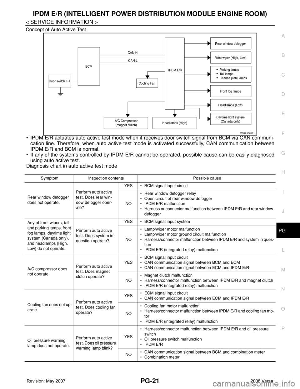
P Concept of Auto Active Test
• IPDM E/R actuates auto active test mode when it receives door switch signal from BCM via CAN communi-
cation line. Therefore, when auto active test mode is activated successfully, CAN communication between
IPDM E/R and BCM is normal.
• If any of the systems controlled by IPDM E/R cannot be operated, possible cause can be easily diagnosed
using auto active test.
Diagnosis chart in auto active test mode
WKIA5665E
Symptom Inspection contents Possible cause
Rear window defogger
does not operate.Perform auto active
test. Does rear win-
dow defogger oper-
ate?YES • BCM signal input circuit
NO• Rear window defogger relay
• Open circuit of rear window defogger
• IPDM E/R malfunction
• Harness or connector malfunction between IPDM E/R and rear window
defogger
Any of front wipers, tail
and parking lamps, front
fog lamps, daytime light
system (Canada only),
and headlamps (High,
Low) do not operate.Perform auto active
test. Does system in
question operate?YES • BCM signal input system
NO• Lamp/wiper motor malfunction
• Lamp/wiper motor ground circuit malfunction
• Harness/connector malfunction between IPDM E/R and system in ques-
tion
• IPDM E/R (integrated relay) malfunction
A/C compressor does
not operate.Perform auto active
test. Does magnet
clutch operate?YES• BCM signal input circuit
• CAN communication signal between BCM and ECM
• CAN communication signal between ECM and IPDM E/R
NO• Magnet clutch malfunction
• Harness/connector malfunction between IPDM E/R and magnet clutch
• IPDM E/R (integrated relay) malfunction
Cooling fan does not op-
erate.Perform auto active
test. Does cooling fan
operate?YES• ECM signal input circuit
• CAN communication signal between ECM and IPDM E/R
NO• Cooling fan motor malfunction
• Harness/connector malfunction between IPDM E/R and cooling fan mo-
tor
• IPDM E/R (integrated relay) malfunction
Oil pressure warning
lamp does not operate.Perform auto active
test. Does oil pressure
warning lamp blink?YES• Harness/connector malfunction between IPDM E/R and oil pressure
switch
• Oil pressure switch malfunction
• IPDM E/R
NO• CAN communication signal between BCM and combination meter
• Combination meter
Page 2456 of 2771

IPDM E/R (INTELLIGENT POWER DISTRIBUTION MODULE ENGINE ROOM)
PG-23
< SERVICE INFORMATION >
C
D
E
F
G
H
I
J
L
MA
B
PG
N
O
P
Terminal and Reference Value for IPDM E/RINFOID:0000000001704703
Te r m i n a lWire
colorSignal nameSignal
input/
outputMeasuring condition
Reference value
(Approx.) Ignition
switchOperation or condition
1 R Battery power supply Input OFF — Battery voltage
2 G Battery power supply Input OFF — Battery voltage
3YECM Relay Output—Ignition switch ON or START Battery voltage
Ignition switch OFF or ACC 0V
4GECM relay Output—Ignition switch ON or START Battery voltage
Ignition switch OFF or ACC 0V
6RDaytime light relay
controlInput ON Daytime light system active. Less than battery voltage
Daytime light system inactive. Battery voltage
7 G ECM relay control Input —Ignition switch ON or START 0V
Ignition switch OFF or ACC Battery voltage
8GThrottle control motor
relayOutput —Ignition switch ON or START Battery voltage
Ignition switch OFF or ACC 0V
11 W A/C compressor OutputON or
STARTA/C switch ON or defrost A/C
switchBattery voltage
A/C switch OFF or defrost A/C
switch0V
12 OIgnition switch sup-
plied powerInput —OFF or ACC 0V
ON or START Battery voltage
14LG
(M/T)
R
(A/T
or
CVT)Fuse 49 Output —Ignition switch ON or START Battery voltage
Ignition switch OFF or ACC 0V
15 V Fuse 50 Output —Ignition switch ON or START Battery voltage
Ignition switch OFF or ACC 0V
16 BR Fuse 51 Output —Ignition switch ON or START Battery voltage
Ignition switch OFF or ACC 0V
17 Y Battery power supply Output — — Battery voltage
19 R Starter motor Output START — Battery voltage
20L
(with
A/C)
LG
(with-
out A/
C)Cooling fan relay-1 Output —Conditions correct for cooling
fan low operation.Battery voltage
Conditions not correct for
cooling fan low operation.0V
22 G Battery power supply Input — — Battery voltage
23 L Cooling fan relay-2 Input —Conditions correct for cooling
fan high operationBattery voltage
Conditions not correct for
cooling fan high operation0V
Page 2457 of 2771

PG-24
< SERVICE INFORMATION >
IPDM E/R (INTELLIGENT POWER DISTRIBUTION MODULE ENGINE ROOM)
24 Y Cooling fan relay-3 Output —Conditions correct for cooling
fan high operationBattery voltage
Conditions not correct for
cooling fan high operation0V
26 OTail lamp relay (park-
ing lamps)Output — Lighting switch in 2nd position Battery voltage
27 BRTail lamp relay (park-
ing lamps)Output — Lighting switch in 2nd position Battery voltage
28 GRTail lamp relay (park-
ing lamps)Output — Lighting switch in 2nd position Battery voltage
29 PTail lamp relay (park-
ing lamps)Output — Lighting switch in 2nd position Battery voltage
30
(A/T
only)R Fuse 54 Output —Ignition switch ON or START Battery voltage
Ignition switch OFF or ACC 0V
31 O Fuse 55 Output —Ignition switch ON or START Battery voltage
Ignition switch OFF or ACC 0V
32 LWiper high speed sig-
nalOutputON or
STARTWiper switchOFF, LO, INT 0V
HI Battery voltage
33 YWiper low speed sig-
nalOutputON or
STARTWiper switchOFF 0V
LO or INT Battery voltage
35 BRStarter relay (inhibit
switch)InputON or
STARTSelector lever in "P" or "N"
(CVT or A/T) or clutch pedal
depressed (M/T)Battery voltage
Selector lever any other posi-
tion (CVT or A/T) or clutch
pedal released (M/T)0V
36 BR Fuel pump relay Output —Ignition switch ON or START Battery voltage
Ignition switch OFF or ACC 0V
37 G Oil pressure switch InputON or
STARTEngine running and oil pres-
sure within specificationBattery voltage
Engine not running or oil pres-
sure below specification0V
38 R Wiper auto stop signal InputON or
STARTWipers not in park position Battery voltage
Wipers in park position 0V
39 B Ground Input — — 0V
40 P CAN-L — ON — —
41 L CAN-H — ON — —
45 R Horn relay control Input —Horn switch PUSHED, alarm
switch activated or door lock/
unlock is confirmed when op-
erating lock system via the
keyfob0V
Horn switch released, alarm
not active, keyfob not activeBattery voltage
46 YThrottle control motor
relay controlInput —Ignition switch ON or START 0V
Ignition switch OFF or ACC Battery voltage
47 GRFuel pump relay con-
trolInput —
Ignition switch ON or START 0V
Ignition switch OFF or ACC Battery voltage Te r m i n a lWire
colorSignal nameSignal
input/
outputMeasuring condition
Reference value
(Approx.) Ignition
switchOperation or condition