Engine NISSAN TIIDA 2008 Service User Guide
[x] Cancel search | Manufacturer: NISSAN, Model Year: 2008, Model line: TIIDA, Model: NISSAN TIIDA 2008Pages: 2771, PDF Size: 60.61 MB
Page 19 of 2771
PRECAUTIONS
AT-7
< SERVICE INFORMATION >
D
E
F
G
H
I
J
K
L
MA
B
AT
N
O
P
PRECAUTIONS
Precaution for Supplemental Restraint System (SRS) "AIR BAG" and "SEAT BELT
PRE-TENSIONER"
INFOID:0000000001703151
The Supplemental Restraint System such as “AIR BAG” and “SEAT BELT PRE-TENSIONER”, used along
with a front seat belt, helps to reduce the risk or severity of injury to the driver and front passenger for certain
types of collision. This system includes seat belt switch inputs and dual stage front air bag modules. The SRS
system uses the seat belt switches to determine the front air bag deployment, and may only deploy one front
air bag, depending on the severity of a collision and whether the front occupants are belted or unbelted.
Information necessary to service the system safely is included in the SRS and SB section of this Service Man-
ual.
WARNING:
• To avoid rendering the SRS inoperative, which could increase the risk of personal injury or death in
the event of a collision which would result in air bag inflation, all maintenance must be performed by
an authorized NISSAN/INFINITI dealer.
• Improper maintenance, including incorrect removal and installation of the SRS, can lead to personal
injury caused by unintentional activation of the system. For removal of Spiral Cable and Air Bag
Module, see the SRS section.
• Do not use electrical test equipment on any circuit related to the SRS unless instructed to in this
Service Manual. SRS wiring harnesses can be identified by yellow and/or orange harnesses or har-
ness connectors.
Precaution Necessary for Steering Wheel Rotation After Battery Disconnect
INFOID:0000000001703152
NOTE:
• This Procedure is applied only to models with Intelligent Key system and NVIS/IVIS (NISSAN/INFINITI
VEHICLE IMMOBILIZER SYSTEM - NATS).
• Remove and install all control units after disconnecting both battery cables with the ignition knob in the
″LOCK″ position.
• Always use CONSULT-III to perform self-diagnosis as a part of each function inspection after finishing work.
If DTC is detected, perform trouble diagnosis according to self-diagnostic results.
For models equipped with the Intelligent Key system and NVIS/IVIS, an electrically controlled steering lock
mechanism is adopted on the key cylinder.
For this reason, if the battery is disconnected or if the battery is discharged, the steering wheel will lock and
steering wheel rotation will become impossible.
If steering wheel rotation is required when battery power is interrupted, follow the procedure below before
starting the repair operation.
OPERATION PROCEDURE
1. Connect both battery cables.
NOTE:
Supply power using jumper cables if battery is discharged.
2. Use the Intelligent Key or mechanical key to turn the ignition switch to the ″ACC″ position. At this time, the
steering lock will be released.
3. Disconnect both battery cables. The steering lock will remain released and the steering wheel can be
rotated.
4. Perform the necessary repair operation.
5. When the repair work is completed, return the ignition switch to the ″LOCK″ position before connecting
the battery cables. (At this time, the steering lock mechanism will engage.)
6. Perform a self-diagnosis check of all control units using CONSULT-III.
Precaution for On Board Diagnosis (OBD) System of A/T and EngineINFOID:0000000001703153
The ECM has an on board diagnostic system. It will light up the malfunction indicator lamp (MIL) to warn the
driver of a malfunction causing emission deterioration.
CAUTION:
Page 21 of 2771
PRECAUTIONS
AT-9
< SERVICE INFORMATION >
D
E
F
G
H
I
J
K
L
MA
B
AT
N
O
P
• Before assembly, apply a coat of recommended ATF to all parts. Apply petroleum jelly to protect O-rings and
seals, or hold bearings and washers in place during assembly. Do not use grease.
• Extreme care should be taken to avoid damage to O-rings, seals and gaskets when assembling.
• Clean or replace ATF cooler if excessive foreign material is found in oil pan or clogging strainer. Refer to
Refer to .
• After overhaul, refill the A/T with new ATF.
• When the A/T drain plug is removed, only some of the fluid is drained. Old A/T fluid will remain in torque con-
verter and ATF cooling system.
Always follow the procedures under “Changing A/T Fluid” in the AT section when changing A/T fluid. Refer to
MA-22, "
Changing A/T Fluid", MA-22, "Checking A/T Fluid".
Service Notice or PrecautionINFOID:0000000001703155
ATF COOLER SERVICE
If A/T fluid contains frictional material (clutches, bands, etc.), or if an A/T is repaired, overhauled, or replaced,
inspect and clean the A/T oil cooler mounted in the radiator or replace the radiator. Flush cooler lines using
cleaning solvent and compressed air after repair. Check Service Bulletins for latest A/T oil cooler cleaning pro-
cedure. For radiator replacement, refer to Refer to CO-11
.
TORQUE CONVERTER SERVICE
The torque converter should be replaced under any of the following conditions:
• External leaks in the hub weld area.
• Converter hub is scored or damaged.
• Converter pilot is broken, damaged or fits poorly into crankshaft.
• Steel particles are found after flushing the cooler and cooler lines.
• Pump is damaged or steel particles are found in the converter.
• Vehicle has TCC shudder and/or no TCC apply. Replace only after all hydraulic and electrical diagnoses
have been made. (Converter clutch material may be glazed.)
• Converter is contaminated with engine coolant containing antifreeze.
• Internal malfunction of stator roller clutch.
• Heavy clutch debris due to overheating (blue converter).
• Steel particles or clutch lining material found in fluid filter or on magnet when no internal parts in unit are
worn or damaged — indicates that lining material came from converter.
The torque converter should not be replaced if:
• The fluid has an odor, is discolored, and there is no evidence of metal or clutch facing particles.
• The threads in one or more of the converter bolt holes are damaged.
• A/T malfunction did not display evidence of damaged or worn internal parts, steel particles or clutch plate lin-
ing material in unit and inside the fluid filter.
• Vehicle has been exposed to high mileage (only). The exception may be where the torque converter clutch
dampener plate lining has seen excess wear by vehicles operated in heavy and/or constant traffic, such as
taxi, delivery or police use.
OBD-II SELF-DIAGNOSIS
• A/T self-diagnosis is performed by the TCM in combination with the ECM. The results can be read through
the blinking pattern of the OD OFF indicator lamp or the malfunction indicator lamp (MIL). Refer to the table
on AT-78, "
Diagnosis Procedure without CONSULT-III" for the indicator used to display each self-diagnostic
result.
• The self-diagnostic results indicated by the MIL are automatically stored in both the ECM and TCM memo-
ries.
Always perform the procedure “HOW TO ERASE DTC” on AT-36, "
OBD-II Diagnostic Trouble Code
(DTC)" to complete the repair and avoid unnecessary blinking of the MIL.
• The following self-diagnostic items can be detected using ECM self-diagnostic results mode* only when the
OD OFF indicator lamp does not indicate any malfunctions.
-PNP switch
- A/T 1st, 2nd, 3rd, or 4th gear function
*: For details of OBD-II, refer to AT- 3 6
.
•Certain systems and components, especially those related to OBD, may use a new style slide-lock-
ing type harness connector.
For description and how to disconnect, refer to PG-65
.
Page 27 of 2771
A/T FLUID
AT-15
< SERVICE INFORMATION >
D
E
F
G
H
I
J
K
L
MA
B
AT
N
O
P
A/T FLUID
Checking A/T FluidINFOID:0000000001703158
1. Warm up engine.
2. Check for A/T fluid leakage.
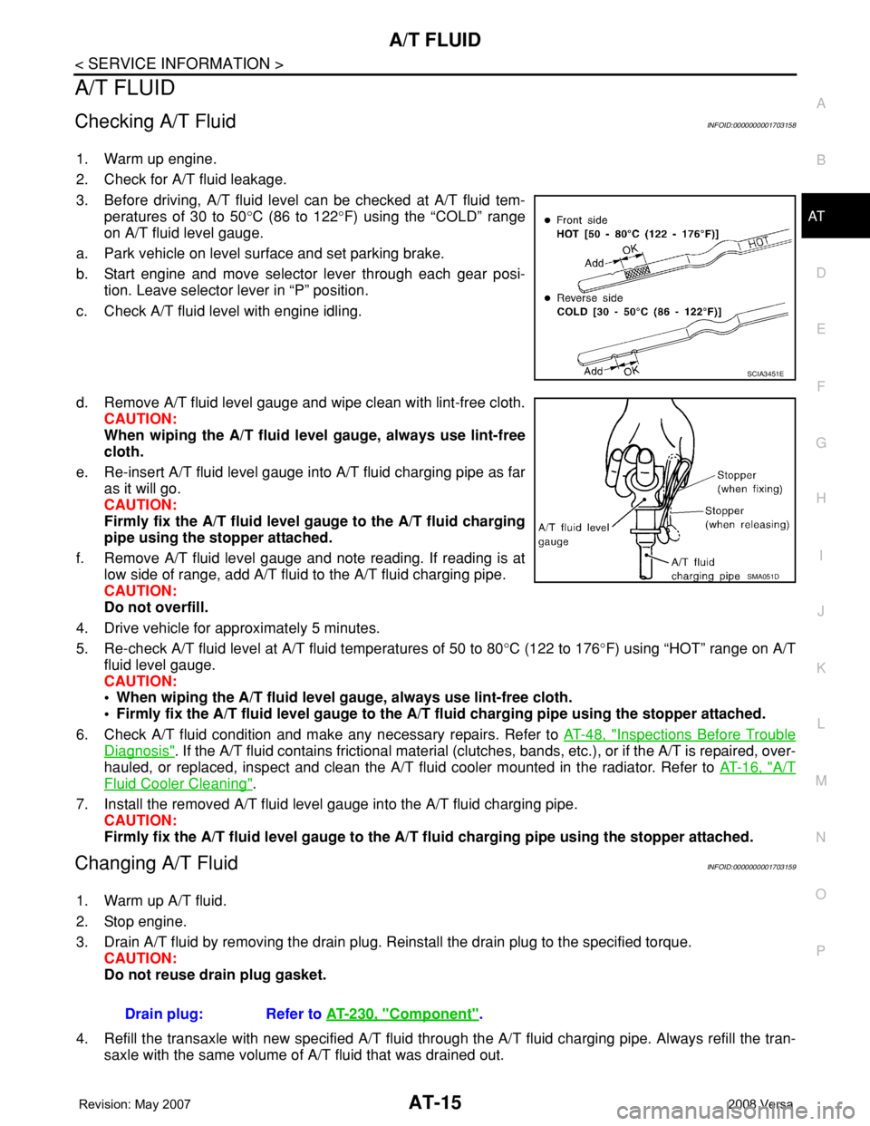
3. Before driving, A/T fluid level can be checked at A/T fluid tem-
peratures of 30 to 50°C (86 to 122°F) using the “COLD” range
on A/T fluid level gauge.
a. Park vehicle on level surface and set parking brake.
b. Start engine and move selector lever through each gear posi-
tion. Leave selector lever in “P” position.
c. Check A/T fluid level with engine idling.
d. Remove A/T fluid level gauge and wipe clean with lint-free cloth.
CAUTION:
When wiping the A/T fluid level gauge, always use lint-free
cloth.
e. Re-insert A/T fluid level gauge into A/T fluid charging pipe as far
as it will go.
CAUTION:
Firmly fix the A/T fluid level gauge to the A/T fluid charging
pipe using the stopper attached.
f. Remove A/T fluid level gauge and note reading. If reading is at
low side of range, add A/T fluid to the A/T fluid charging pipe.
CAUTION:
Do not overfill.
4. Drive vehicle for approximately 5 minutes.
5. Re-check A/T fluid level at A/T fluid temperatures of 50 to 80°C (122 to 176°F) using “HOT” range on A/T
fluid level gauge.
CAUTION:
• When wiping the A/T fluid level gauge, always use lint-free cloth.
• Firmly fix the A/T fluid level gauge to the A/T fluid charging pipe using the stopper attached.
6. Check A/T fluid condition and make any necessary repairs. Refer to AT-48, "
Inspections Before Trouble
Diagnosis". If the A/T fluid contains frictional material (clutches, bands, etc.), or if the A/T is repaired, over-
hauled, or replaced, inspect and clean the A/T fluid cooler mounted in the radiator. Refer to AT-16, "
A/T
Fluid Cooler Cleaning".
7. Install the removed A/T fluid level gauge into the A/T fluid charging pipe.
CAUTION:
Firmly fix the A/T fluid level gauge to the A/T fluid charging pipe using the stopper attached.
Changing A/T FluidINFOID:0000000001703159
1. Warm up A/T fluid.
2. Stop engine.
3. Drain A/T fluid by removing the drain plug. Reinstall the drain plug to the specified torque.
CAUTION:
Do not reuse drain plug gasket.
4. Refill the transaxle with new specified A/T fluid through the A/T fluid charging pipe. Always refill the tran-
saxle with the same volume of A/T fluid that was drained out.
SCIA3451E
SMA051D
Drain plug: Refer to AT-230, "Component".
Page 28 of 2771
AT-16
< SERVICE INFORMATION >
A/T FLUID
5. Run engine at idle speed for 5 minutes.
6. Check A/T fluid level and condition. Refer to MA-22, "
Checking A/T Fluid".
A/T Fluid Cooler CleaningINFOID:0000000001703160
Whenever the A/T is repaired, overhauled, or replaced, the A/T fluid cooler mounted in the radiator must be
inspected and cleaned.
Metal debris and friction material, if present, can become trapped in the A/T fluid cooler. This debris can con-
taminate the newly serviced A/T or, in severe cases, can block or restrict the flow of A/T fluid. In either case,
malfunction of the newly serviced A/T may result.
Debris, if present, may build up as A/T fluid enters the cooler inlet. It will be necessary to back flush the cooler
through the cooler outlet in order to flush out any built up debris.
A/T FLUID COOLER CLEANING PROCEDURE
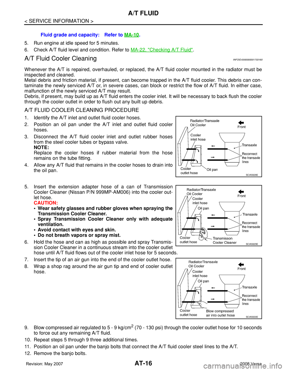
1. Identify the A/T inlet and outlet fluid cooler hoses.
2. Position an oil pan under the A/T inlet and outlet fluid cooler
hoses.
3. Disconnect the A/T fluid cooler inlet and outlet rubber hoses
from the steel cooler tubes or bypass valve.
NOTE:
Replace the cooler hoses if rubber material from the hose
remains on the tube fitting.
4. Allow any A/T fluid that remains in the cooler hoses to drain into
the oil pan.
5. Insert the extension adapter hose of a can of Transmission
Cooler Cleaner (Nissan P/N 999MP-AM006) into the cooler out-
let hose.
CAUTION:
• Wear safety glasses and rubber gloves when spraying the
Transmission Cooler Cleaner.
• Spray Transmission Cooler Cleaner only with adequate
ventilation.
• Avoid contact with eyes and skin.
• Do not breath vapors or spray mist.
6. Hold the hose and can as high as possible and spray Transmis-
sion Cooler Cleaner in a continuous stream into the cooler outlet
hose until A/T fluid flows out of the cooler inlet hose for 5 seconds.
7. Insert the tip of an air gun into the end of the cooler outlet hose.
8. Wrap a shop rag around the air gun tip and end of cooler outlet
hose.
9. Blow compressed air regulated to 5 - 9 kg/cm
2 (70 - 130 psi) through the cooler outlet hose for 10 seconds
to force out any remaining A/T fluid.
10. Repeat steps 5 through 9 three additional times.
11. Position an oil pan under the banjo bolts that connect the A/T fluid cooler steel lines to the A/T.
12. Remove the banjo bolts.Fluid grade and capacity: Refer to MA-10
.
SCIA5628E
SCIA5629E
SCIA5630E
Page 32 of 2771
AT-20
< SERVICE INFORMATION >
A/T CONTROL SYSTEM
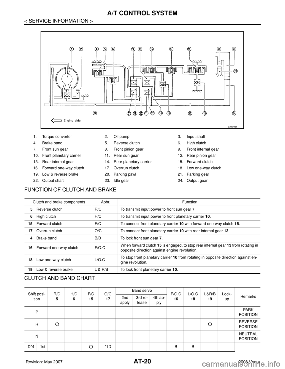
FUNCTION OF CLUTCH AND BRAKE
CLUTCH AND BAND CHART
1. Torque converter 2. Oil pump 3. Input shaft
4. Brake band 5. Reverse clutch 6. High clutch
7. Front sun gear 8. Front pinion gear 9. Front internal gear
10. Front planetary carrier 11. Rear sun gear 12. Rear pinion gear
13. Rear internal gear 14. Rear planetary carrier 15. Forward clutch
16. Forward one-way clutch 17. Overrun clutch 18. Low one-way clutch
19. Low & reverse brake 20. Parking pawl 21. Parking gear
22. Output shaft 23. Idle gear 24. Output gear
SAT998I
Clutch and brake components Abbr. Function
5Reverse clutch R/C To transmit input power to front sun gear 7.
6High clutch H/C To transmit input power to front planetary carrier 10.
15Forward clutch F/C To connect front planetary carrier 10 with forward one-way clutch 16.
17Overrun clutch O/C To connect front planetary carrier 10 with rear internal gear 13.
4Brake band B/B To lock front sun gear 7.
16Forward one-way clutch F/O.CWhen forward clutch 15 is engaged, to stop rear internal gear 13 from rotating in
opposite direction against engine revolution.
18Low one-way clutch L/O.CTo stop front planetary carrier 10 from rotating in opposite direction against en-
gine revolution.
19Low & reverse brake L & R/B To lock front planetary carrier 10.
Shift posi-
tionR/C
5H/C
6F/C
15O/C
17Band servo
F/O.C
16L/O.C
18L&R/B
19Lock-
upRemarks
2nd
apply3rd re-
lease4th ap-
ply
PPA R K
POSITION
RREVERSE
POSITION
NNEUTRAL
POSITION
D*4 1st *1D B B
Page 33 of 2771
A/T CONTROL SYSTEM
AT-21
< SERVICE INFORMATION >
D
E
F
G
H
I
J
K
L
MA
B
AT
N
O
P
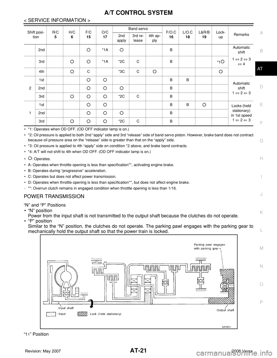
• *1: Operates when OD OFF. (OD OFF indicator lamp is on.)
• *2: Oil pressure is applied to both 2nd “apply” side and 3rd “release” side of band servo piston. However, brake band does not contract
because oil pressure area on the “release” side is greater than that on the “apply” side.
• *3: Oil pressure is applied to 4th “apply” side on condition *2 above, and brake band contracts.
• *4: A/T will not shift to 4th when OD OFF. (OD OFF indicator lamp is on.)
• : Operates.
• A: Operates when throttle opening is less than specification**, activating engine brake.
• B: Operates during “progressive” acceleration.
• C: Operates but does not affect power transmission.
• D: Operates when throttle opening is less than specification**, but does not affect engine brake.
- **: Overrun clutch remains in engaged condition when throttle opening is less than 1/16.
POWER TRANSMISSION
“N” and “P” Positions
• “N” position
Power from the input shaft is not transmitted to the output shaft because the clutches do not operate.
• “P” position
Similar to the “N” position, the clutches do not operate. The parking pawl engages with the parking gear to
mechanically hold the output shaft so that the power train is locked.
“11” Position
2nd *1A BAutomatic
shift
3rd *1A *2C C B
*11 ⇔ 2 ⇔ 3
⇔ 4
4th C *3C C
21stBB
Automatic
shift
1 ⇔ 2 ⇐ 3 2ndB
3rd *2C C B
11stBB
Locks (held
stationary)
in 1st speed
1 ⇐ 2 ⇐ 3 2ndB
3rd *2C C B Shift posi-
tionR/C
5H/C
6F/C
15O/C
17Band servo
F/O.C
16L/O.C
18L&R/B
19Lock-
upRemarks
2nd
apply3rd re-
lease4th ap-
ply
SAT991I
Page 34 of 2771
AT-22
< SERVICE INFORMATION >
A/T CONTROL SYSTEM
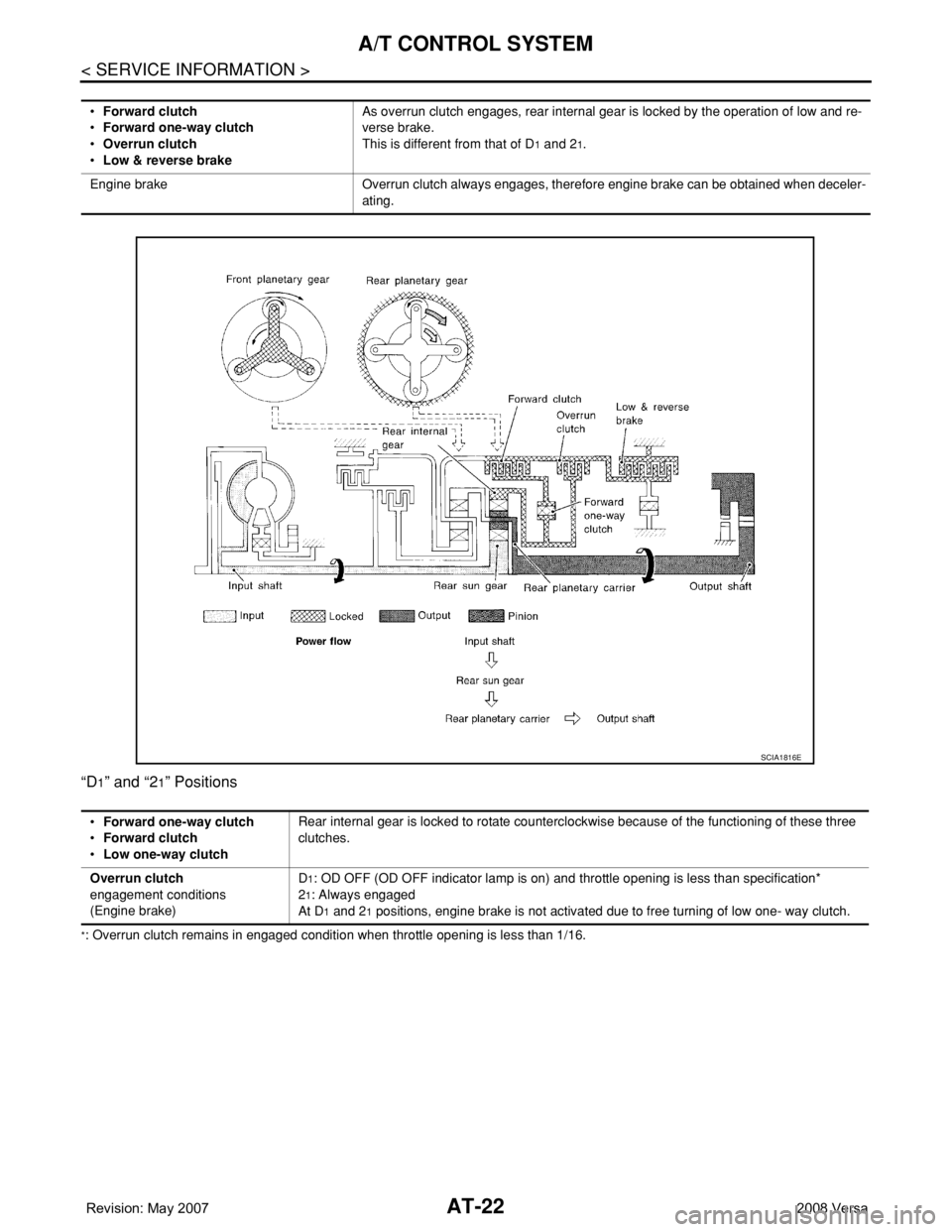
“D1” and “21” Positions
*: Overrun clutch remains in engaged condition when throttle opening is less than 1/16.•Forward clutch
•Forward one-way clutch
•Overrun clutch
•Low & reverse brakeAs overrun clutch engages, rear internal gear is locked by the operation of low and re-
verse brake.
This is different from that of D
1 and 21.
Engine brake Overrun clutch always engages, therefore engine brake can be obtained when deceler-
ating.
SCIA1816E
•Forward one-way clutch
•Forward clutch
•Low one-way clutchRear internal gear is locked to rotate counterclockwise because of the functioning of these three
clutches.
Overrun clutch
engagement conditions
(Engine brake)D
1: OD OFF (OD OFF indicator lamp is on) and throttle opening is less than specification*
2
1: Always engaged
At D
1 and 21 positions, engine brake is not activated due to free turning of low one- way clutch.
Page 37 of 2771
A/T CONTROL SYSTEM
AT-25
< SERVICE INFORMATION >
D
E
F
G
H
I
J
K
L
MA
B
AT
N
O
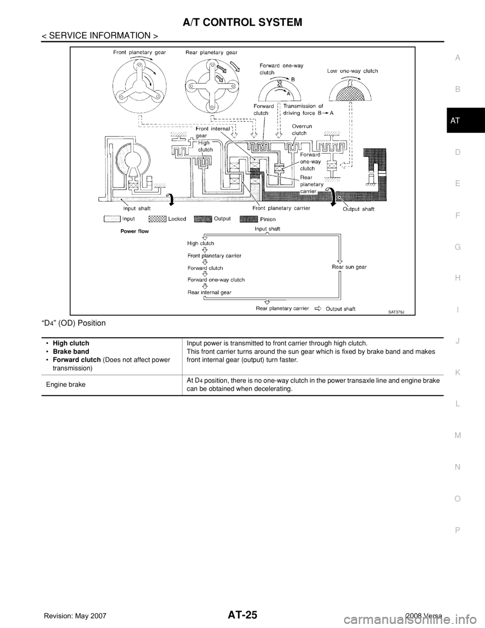
P “D
4” (OD) Position
SAT379J
•High clutch
•Brake band
•Forward clutch (Does not affect power
transmission)Input power is transmitted to front carrier through high clutch.
This front carrier turns around the sun gear which is fixed by brake band and makes
front internal gear (output) turn faster.
Engine brakeAt D
4 position, there is no one-way clutch in the power transaxle line and engine brake
can be obtained when decelerating.
Page 38 of 2771
AT-26
< SERVICE INFORMATION >
A/T CONTROL SYSTEM
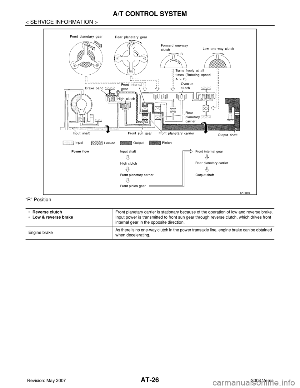
“R” Position
SAT380J
•Reverse clutch
•Low & reverse brakeFront planetary carrier is stationary because of the operation of low and reverse brake.
Input power is transmitted to front sun gear through reverse clutch, which drives front
internal gear in the opposite direction.
Engine brakeAs there is no one-way clutch in the power transaxle line, engine brake can be obtained
when decelerating.
Page 39 of 2771
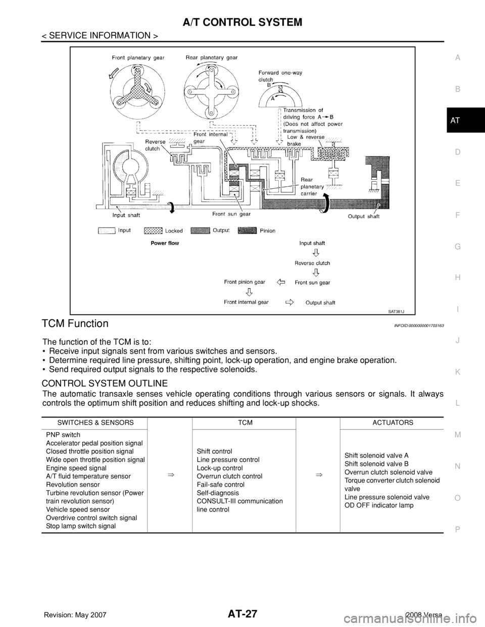
A/T CONTROL SYSTEM
AT-27
< SERVICE INFORMATION >
D
E
F
G
H
I
J
K
L
MA
B
AT
N
O
P
TCM FunctionINFOID:0000000001703163
The function of the TCM is to:
• Receive input signals sent from various switches and sensors.
• Determine required line pressure, shifting point, lock-up operation, and engine brake operation.
• Send required output signals to the respective solenoids.
CONTROL SYSTEM OUTLINE
The automatic transaxle senses vehicle operating conditions through various sensors or signals. It always
controls the optimum shift position and reduces shifting and lock-up shocks.
SAT381J
SWITCHES & SENSORS
⇒TCM
⇒ACTUATORS
PNP switch
Accelerator pedal position signal
Closed throttle position signal
Wide open throttle position signal
Engine speed signal
A/T fluid temperature sensor
Revolution sensor
Turbine revolution sensor (Power
train revolution sensor)
Vehicle speed sensor
Overdrive control switch signal
Stop lamp switch signalShift control
Line pressure control
Lock-up control
Overrun clutch control
Fail-safe control
Self-diagnosis
CONSULT-III communication
line controlShift solenoid valve A
Shift solenoid valve B
Overrun clutch solenoid valve
Torque converter clutch solenoid
valve
Line pressure solenoid valve
OD OFF indicator lamp