transmission NISSAN TIIDA 2008 Service User Guide
[x] Cancel search | Manufacturer: NISSAN, Model Year: 2008, Model line: TIIDA, Model: NISSAN TIIDA 2008Pages: 2771, PDF Size: 60.61 MB
Page 118 of 2771
AT-106
< SERVICE INFORMATION >
DTC P0731 A/T 1ST GEAR FUNCTION
5. Accelerate vehicle to 20 to 25 km/h (12 to 16 MPH) under the following conditions and release the accel-
erator pedal completely.
THROTTLE POSI: Less than 1.0/8 (at all times during step 4)
SLCT LVR POSI: “D” position
-Make sure that “GEAR” shows “2” after releasing pedal.
6. Depress accelerator pedal to WOT (more than 7.0/8 of “THROTTLE POSI”) quickly from a speed of 20 to
25 km/h (12 to 16 MPH) until “TESTING” changes to “STOP VEHICLE” or “COMPLETED”. (It will take
approximately 3 seconds.)
If the check result NG appears on CONSULT-III screen, go to AT-106, "
Diagnosis Procedure".
If “STOP VEHICLE” appears on CONSULT-III screen, go to the following step.
-Make sure that “GEAR” shows “1” when depressing accelerator pedal to WOT.
-If “TESTING” does not appear on CONSULT-III for a long time, select “SELF-DIAG RESULTS” for
“A/T”. In case a DTC other than “P0731 A/T 1ST GR FNCTN” is shown, refer to AT-73, "
CONSULT-III
Function (A/T)".
7. Stop vehicle.
8. Follow the instruction displayed. (Check for normal shifting referring to the table below.)
9. Make sure that “OK” is displayed. (If “NG” is displayed, refer to “Diagnostic Procedure”.)
Refer to AT-106, "
Diagnosis Procedure".
Refer to AT-61, "
Vehicle Speed at Which Gear Shifting Occurs".
WITH GST
Follow the procedure “WITH CONSULT-III”.
Diagnosis ProcedureINFOID:0000000001703235
1.CHECK VALVE RESISTANCE
1. Remove control valve assembly. Refer to AT-216, "
Control Valve Assembly and Accumulators".
- Shift solenoid valve A
- Shift solenoid valve B
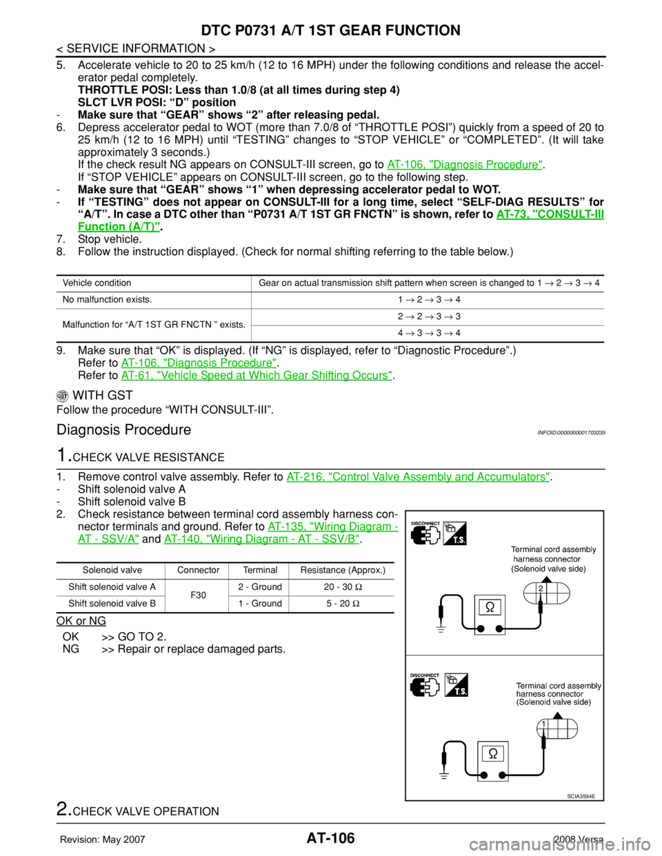
2. Check resistance between terminal cord assembly harness con-
nector terminals and ground. Refer to AT-135, "
Wiring Diagram -
AT - SSV/A" and AT-140, "Wiring Diagram - AT - SSV/B".
OK or NG
OK >> GO TO 2.
NG >> Repair or replace damaged parts.
2.CHECK VALVE OPERATION
Vehicle condition Gear on actual transmission shift pattern when screen is changed to 1 → 2 → 3 → 4
No malfunction exists. 1 → 2 → 3 → 4
Malfunction for “A/T 1ST GR FNCTN ” exists.2 → 2 → 3 → 3
4 → 3 → 3 → 4
Solenoid valve Connector Terminal Resistance (Approx.)
Shift solenoid valve A
F302 - Ground 20 - 30 Ω
Shift solenoid valve B 1 - Ground 5 - 20 Ω
SCIA3594E
Page 121 of 2771
DTC P0732 A/T 2ND GEAR FUNCTION
AT-109
< SERVICE INFORMATION >
D
E
F
G
H
I
J
K
L
MA
B
AT
N
O
P
-Make sure that “GEAR” shows “3” or “4” after releasing pedal.
6. Depress accelerator pedal to WOT (more than 7.0/8 of “THROTTLE POSI”) quickly from a speed of 45 to
50 km/h (28 to 31 MPH) until “TESTING” changes to “STOP VEHICLE” or “COMPLETE”. (It will take
approximately 3 seconds.)
If the check result NG appears on CONSULT-III screen, go to AT-109, "
Diagnosis Procedure".
If “STOP VEHICLE” appears on CONSULT-III screen, go to following step.
-Make sure that “GEAR” shows “2” when depressing accelerator pedal to WOT.
-If “TESTING” does not appear on CONSULT-III for a long time, select “SELF-DIAG RESULTS” for
“A/T”. In case a DTC other than “P0732 A/T 2ND GR FNCTN” is shown, refer to AT-73, "
CONSULT-
III Function (A/T)".
7. Stop vehicle.
8. Follow the instruction displayed. (Check for normal shifting referring to the table below.)
9. Make sure that “OK” is displayed. (If “NG” is displayed, refer to “Diagnostic Procedure”.)
Refer to AT-109, "
Diagnosis Procedure".
Refer to AT-61, "
Vehicle Speed at Which Gear Shifting Occurs".
WITH GST
Follow the procedure “WITH CONSULT-III”.
Diagnosis ProcedureINFOID:0000000001703240
1.CHECK VALVE RESISTANCE
1. Remove control valve assembly. Refer to AT-216, "
Control Valve Assembly and Accumulators".
- Shift solenoid valve B
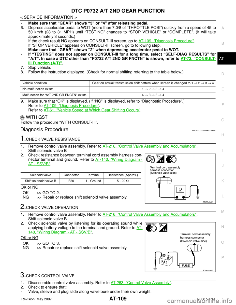
2. Check resistance between terminal cord assembly harness con-
nector terminal and ground. Refer to AT-140, "
Wiring Diagram -
AT - SSV/B".
OK or NG
OK >> GO TO 2.
NG >> Repair or replace shift solenoid valve assembly.
2.CHECK VALVE OPERATION
1. Remove control valve assembly. Refer to AT-216, "
Control Valve Assembly and Accumulators".
- Shift solenoid valve B
2. Check solenoid valve by listening for its operating sound while
applying battery voltage to the terminal and ground. Refer to AT-
140, "Wiring Diagram - AT - SSV/B".
OK or NG
OK >> GO TO 3.
NG >> Repair or replace shift solenoid valve assembly.
3.CHECK CONTROL VALVE
1. Disassemble control valve assembly. Refer to AT-263, "
Control Valve Assembly".
2. Check to ensure that:
- Valve, sleeve and plug slide along valve bore under their own weight.
Vehicle condition Gear on actual transmission shift pattern when screen is changed to 1 → 2 → 3 → 4
No malfunction exists 1 → 2 → 3 → 4
Malfunction for “A/T 2ND GR FNCTN” exists. 4 → 3 → 3 → 4
Solenoid valve Connector Terminal Resistance (Approx.)
Shift solenoid valve B F30 1 - Ground 5 - 20 Ω
SCIA3454E
SCIA2058E
Page 124 of 2771

AT-112
< SERVICE INFORMATION >
DTC P0733 A/T 3RD GEAR FUNCTION
-Make sure that “GEAR” shows “4” after releasing pedal.
6. Depress accelerator pedal steadily with 3.5/8 - 4.5/8 of “THROTTLE POSI” from a speed of 60 to 75 km/h
(37 to 47 MPH) until “TESTING” changes to “STOP VEHICLE” or “COMPLETED”. (It will take approxi-
mately 3 seconds.)
If the check result NG appears on CONSULT-III screen, go to AT-112, "
Diagnosis Procedure".
If “STOP VEHICLE” appears on CONSULT-III screen, go to following step.
-Make sure that “GEAR” shows “3” when depressing accelerator pedal with 3.5/8 - 4.5/8 of
“THROTTLE POSI”.
-If “TESTING” does not appear on CONSULT-III for a long time, select “SELF-DIAG RESULTS” for
“A/T”. In case a DTC other than “P0733 A/T 3RD GR FNCTN” is shown, refer to AT-73, "
CONSULT-
III Function (A/T)".
7. Stop vehicle.
8. Follow the instruction displayed. (Check for normal shifting referring to the table below.)
9. Make sure that “OK” is displayed. (If “NG” is displayed, refer to “Diagnostic Procedure”.)
Refer to AT-112, "
Diagnosis Procedure".
Refer to AT-61, "
Vehicle Speed at Which Gear Shifting Occurs".
WITH GST
Follow the procedure “WITH CONSULT-III”.
Diagnosis ProcedureINFOID:0000000001703245
1.CHECK VALVE RESISTANCE
1. Remove control valve assembly. Refer to AT-216, "
Control Valve Assembly and Accumulators".
- Shift solenoid valve A
- Shift solenoid valve B
2. Check resistance between terminal cord assembly harness con-
nector terminals and ground. Refer to AT-135, "
Wiring Diagram -
AT - SSV/A" and AT-140, "Wiring Diagram - AT - SSV/B".
OK or NG
OK >> GO TO 2.
NG >> Repair or replace shift solenoid valve assembly.
2.CHECK VALVE OPERATION
1. Remove control valve assembly. Refer to AT-216, "
Control Valve Assembly and Accumulators".
- Shift solenoid valve A
- Shift solenoid valve B
Vehicle condition Gear on actual transmission shift pattern when screen is changed to 1 → 2 → 3 → 4
No malfunction exists. 1 → 2 → 3 → 4
Malfunction for “A/T 3RD GR FNCTN” exists. 1 → 1 → 4 → 4
Solenoid valve Connector Terminal Resistance (Approx.)
Shift solenoid valve A
F302 - Ground 20 - 30 Ω
Shift solenoid valve B 1 - Ground 5 - 20 Ω
SCIA3594E
Page 127 of 2771
DTC P0734 A/T 4TH GEAR FUNCTION
AT-115
< SERVICE INFORMATION >
D
E
F
G
H
I
J
K
L
MA
B
AT
N
O
P
WITH CONSULT-III
1. Start engine and select “DATA MONITOR” mode for “A/T” with CONSULT-III.
2. Touch “START”.
3. Make sure that output voltage of A/T fluid temperature sensor is within the range below.
FLUID TEMP SE: 0.4 - 1.5 V
If out of range, drive the vehicle to decrease the voltage (warm up the fluid) or stop engine to increase the
voltage (cool down the fluid).
4. Select “4TH GR FNCTN P0734” of “DTC WORK SUPPORT” mode for “A/T” with CONSULT-III and touch
“START”.
5. Accelerate vehicle to 55 to 65 km/h (34 to 40 MPH) under the following conditions and release the accel-
erator pedal completely.
THROTTLE POSI: Less than 5.5/8 (at all times during step 4)
SLCT LVR POSI: “D” position
-Make sure that “GEAR” shows “3” after releasing pedal.
6. Depress accelerator pedal steadily with 1.0/8 - 2.0/8 of “THROTTLE POSI” from a speed of 55 to 65 km/h
(34 to 40 MPH) until “TESTING” has turned to “STOP VEHICLE” or “COMPLETED”. (It will take approxi-
mately 3 seconds.)
If the check result NG appears on CONSULT-III screen, go to AT-115, "
Diagnosis Procedure".
If “STOP VEHICLE” appears on CONSULT-III screen, go to following step.
-Make sure that “GEAR” shows “4” when depressing accelerator pedal with 1.0/8 - 2.0/8 of
“THROTTLE POSI”.
-If “TESTING” does not appear on CONSULT-III for a long time, select “SELF-DIAG RESULTS” for
“A/T”. In case a DTC other than “P0734 A/T 4TH GR FNCTN” is shown, refer to AT-73, "
CONSULT-
III Function (A/T)".
7. Stop vehicle.
8. Follow the instruction displayed. (Check for normal shifting referring to the table below.)
9. Make sure that “OK” is displayed. (If “NG” is displayed, refer to “Diagnostic Procedure”.)
Refer to AT-115, "
Diagnosis Procedure".
Refer to AT-61, "
Vehicle Speed at Which Gear Shifting Occurs".
WITH GST
Follow the procedure “WITH CONSULT-III”.
Diagnosis ProcedureINFOID:0000000001703251
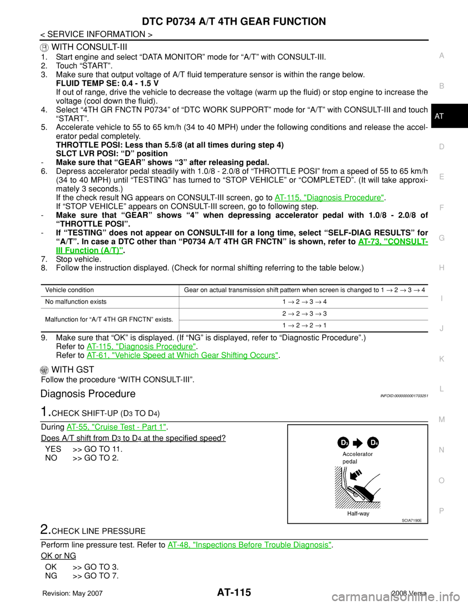
1.CHECK SHIFT-UP (D3 TO D4)
During AT-55, "
Cruise Test - Part 1".
Does A/T shift from D
3 to D4 at the specified speed?
YES >> GO TO 11.
NO >> GO TO 2.
2.CHECK LINE PRESSURE
Perform line pressure test. Refer to AT-48, "
Inspections Before Trouble Diagnosis".
OK or NG
OK >> GO TO 3.
NG >> GO TO 7.
Vehicle condition Gear on actual transmission shift pattern when screen is changed to 1 → 2 → 3 → 4
No malfunction exists 1 → 2 → 3 → 4
Malfunction for “A/T 4TH GR FNCTN” exists.2 → 2 → 3 → 3
1 → 2 → 2 → 1
SCIA7190E
Page 214 of 2771
AT-202
< SERVICE INFORMATION >
TRANSMISSION CONTROL MODULE
TRANSMISSION CONTROL MODULE
Removal and InstallationINFOID:0000000001703355
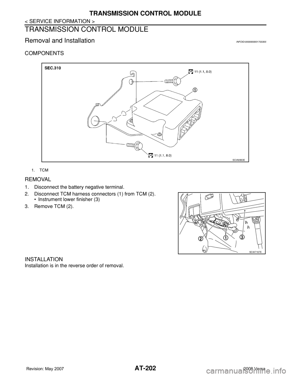
COMPONENTS
REMOVAL
1. Disconnect the battery negative terminal.
2. Disconnect TCM harness connectors (1) from TCM (2).
• Instrument lower finisher (3)
3. Remove TCM (2).
INSTALLATION
Installation is in the reverse order of removal.
1. TCM
SCIA6963E
SCIA7167E
Page 240 of 2771
AT-228
< SERVICE INFORMATION >
TRANSAXLE ASSEMBLY
• When replacing an engine or transmission you must make sure any dowels are installed correctly
during re-assembly.
• Improper alignment caused by missing dowels may cause vibration, oil leaks or breakage of drive
train components.
• Do not reuse O-rings and copper washers. Refer to "COMPONENTS".
• When turning crankshaft, turn it clockwise as viewed from the front of the engine.
• When tightening the bolts for the torque converter while securing the crankshaft pulley bolt, be sure
to confirm the tightening torque of the crankshaft pulley bolt. Refer to EM-37
.
• After converter is installed to drive plate, rotate crankshaft several turns to check that transaxle
rotates freely without binding.
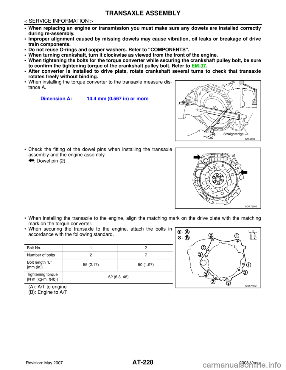
• When installing the torque converter to the transaxle measure dis-
tance A.
• Check the fitting of the dowel pins when installing the transaxle
assembly and the engine assembly.
: Dowel pin (2)
• When installing the transaxle to the engine, align the matching mark on the drive plate with the matching
mark on the torque converter.
• When securing the transaxle to the engine, attach the bolts in
accordance with the following standard.
(A): A/T to engine
(B): Engine to A/TDimension A: 14.4 mm (0.567 in) or more
SAT430D
SCIA7698E
Bolt No. 1 2
Number of bolts 2 7
Bolt length “L”
[mm (in)]55 (2.17) 50 (1.97)
Tightening torque
[N·m (kg-m, ft-lb)]62 (6.3, 46)
SCIA7685E
Page 353 of 2771

SERVICE DATA AND SPECIFICATIONS (SDS)
AT-341
< SERVICE INFORMATION >
D
E
F
G
H
I
J
K
L
MA
B
AT
N
O
P
SERVICE DATA AND SPECIFICATIONS (SDS)
General SpecificationINFOID:0000000001703396
*: Refer to MA-10.
Vehicle Speed at Which Gear Shifting OccursINFOID:0000000001703397
• At half throttle, the accelerator opening is 4/8 of the full opening.
Vehicle Speed at When Lock-up Occurs/ReleasesINFOID:0000000001703398
Stall SpeedINFOID:0000000001703399
Line PressureINFOID:0000000001703400
Adjusting shims, Needle Bearings, Thrust Washers and Snap RingsINFOID:0000000001703401
NOTE:
EngineMR18DE
Automatic transaxle model RE4F03B
Automatic transaxle assembly Model code number 3CX0D
Transaxle gear ratio1st 2.861
2nd 1.562
3rd 1.000
4th 0.697
Reverse 2.310
Final drive 4.072
Recommended fluidGenuine NISSAN Matic D ATF (Continental U.S. and Alaska) or
Canada NISSAN Automatic Transmission Fluid*
Fluid capacity [ (US qt, Imp qt)]7.9 (8-3/8, 7)
Throttle positionVehicle speed km/h (MPH)
D1 → D2D2 → D3D3 → D4D4 → D3D3 → D2D2 → D1
Full throttle51 - 59
(32 - 37)97 - 105
(60 - 65)154 - 162
(96 - 101)150 - 158
(93 - 98)87 - 95
(54 - 59)40 - 48
(25 - 30)
Half throttle34 - 42
(21 - 26)62 - 70
(39 - 43)124 - 132
(77 - 82)69 - 77
(43 - 48)36 - 44
(22 - 27)19 - 27
(12 - 17)
Throttle position Selector lever positionVehicle speed km/h (MPH)
Lock-up ON Lock-up OFF
2.0/8“D” position 86 - 94 (53 - 58) 59 - 67 (37 - 42)
“D” position (OD OFF) 86 - 94 (53 - 58) 83 - 91 (52 - 57)
Stall revolution (rpm)2,310 - 2,770
Engine speedLine pressure kPa (kg/cm2, psi)
“D”, “2” and “1” positions “R” position
Idle speed 500 (5.1, 73) 778 (7.9, 113)
Stall speed 1,173 (12.0, 170) 1,825 (18.6, 265)
Page 510 of 2771
BL-76
< SERVICE INFORMATION >
INTELLIGENT KEY SYSTEM
System Description
INFOID:0000000001703999
• The Intelligent Key system is a system that makes it possible to lock and unlock the door locks (door lock/
unlock function), and start the engine (engine start function) by carrying around the Intelligent Key (without
some key operation), which operates based on the results of electronic ID verification using two-way com-
munications between the Intelligent Key and the vehicle (Intelligent Key unit).
• Vehicles equipped with a manual transmission include a key interlock solenoid located in the steering col-
umn to prevent accidental shut-off of the ignition switch and locking of the steering wheel during driving con-
dition when the vehicle is moving.
CAUTION:
The driver should always carry the Intelligent Key
• Operation of the remote controller buttons on the Intelligent Key also provides the same functions as the
remote control entry system. (Remote keyless entry functions)
• If an action that does not meet the operating conditions of the Intelligent Key system is taken, the buzzer
goes off to inform the driver. (Warning chime functions)
• When a door lock is locked or unlocked with request switch or remote controller button operation, the hazard
lamps flash and the buzzer (outside vehicle) sounds (Hazard and buzzer reminder function).
• Even if the Intelligent Key battery is completely discharged, the door locks can be locked and unlocked and
the engine started with the mechanical key built into the Intelligent Key.
• The settings for each function can be changed with the CONSULT-III.
• If an Intelligent Key is lost, a new Intelligent Key can be registered. A maximum of 4 Intelligent Keys can be
registered.
• It has been made possible to diagnose the system and register an Intelligent Key with the CONSULT-III.
DOOR LOCK/UNLOCK FUNCTION
Only when pressing the request switch, it is possible to lock and unlock the door by carrying around the Intelli-
gent Key (without some key operation).
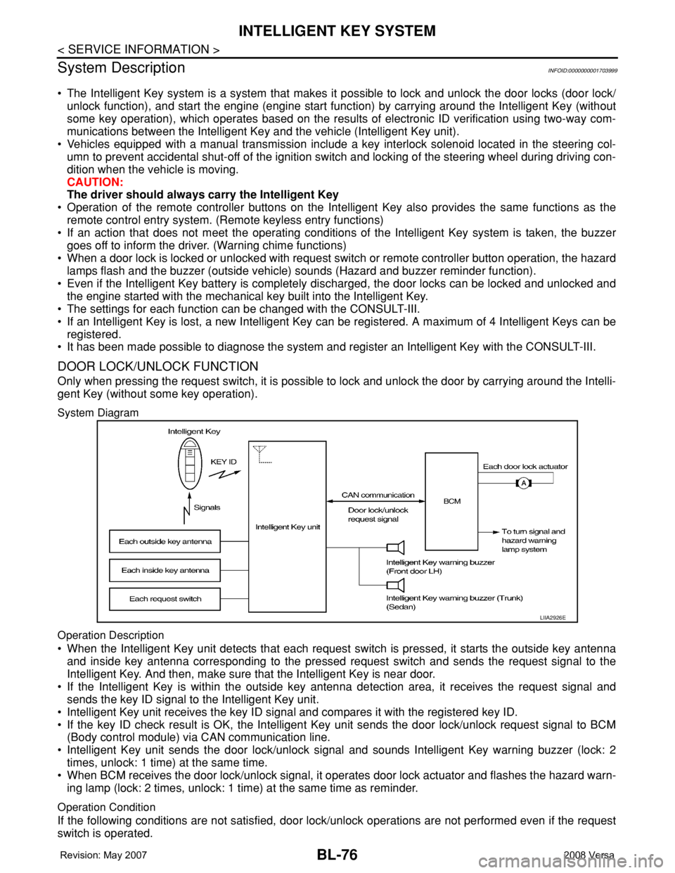
System Diagram
Operation Description
• When the Intelligent Key unit detects that each request switch is pressed, it starts the outside key antenna
and inside key antenna corresponding to the pressed request switch and sends the request signal to the
Intelligent Key. And then, make sure that the Intelligent Key is near door.
• If the Intelligent Key is within the outside key antenna detection area, it receives the request signal and
sends the key ID signal to the Intelligent Key unit.
• Intelligent Key unit receives the key ID signal and compares it with the registered key ID.
• If the key ID check result is OK, the Intelligent Key unit sends the door lock/unlock request signal to BCM
(Body control module) via CAN communication line.
• Intelligent Key unit sends the door lock/unlock signal and sounds Intelligent Key warning buzzer (lock: 2
times, unlock: 1 time) at the same time.
• When BCM receives the door lock/unlock signal, it operates door lock actuator and flashes the hazard warn-
ing lamp (lock: 2 times, unlock: 1 time) at the same time as reminder.
Operation Condition
If the following conditions are not satisfied, door lock/unlock operations are not performed even if the request
switch is operated.
LIIA2926E
Page 532 of 2771
BL-98
< SERVICE INFORMATION >
INTELLIGENT KEY SYSTEM
*1: With continuously variable transmission (CVT).
*2: With manual transmission (M/T).
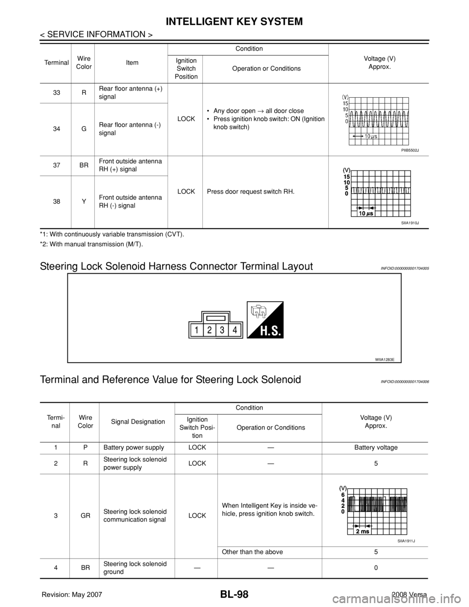
Steering Lock Solenoid Harness Connector Terminal LayoutINFOID:0000000001704005
Terminal and Reference Value for Steering Lock SolenoidINFOID:0000000001704006
33 RRear floor antenna (+)
signal
LOCK• Any door open → all door close
• Press ignition knob switch: ON (Ignition
knob switch)
34 GRear floor antenna (-)
signal
37 BRFront outside antenna
RH (+) signal
LOCK Press door request switch RH.
38 YFront outside antenna
RH (-) signal Te r m i n a lWire
ColorItemCondition
Voltage (V)
Approx. Ignition
Switch
PositionOperation or Conditions
PIIB5502J
SIIA1910J
WIIA1283E
Te r m i -
nalWire
ColorSignal DesignationCondition
Voltage (V)
Approx. Ignition
Switch Posi-
tionOperation or Conditions
1 P Battery power supply LOCK — Battery voltage
2RSteering lock solenoid
power supplyLOCK — 5
3GRSteering lock solenoid
communication signalLOCKWhen Intelligent Key is inside ve-
hicle, press ignition knob switch.
Other than the above 5
4BRSteering lock solenoid
ground—— 0
SIIA1911J
Page 802 of 2771

CL-1
TRANSMISSION/TRANSAXLE
D
E
F
G
H
I
J
K
L
M
SECTION CL
A
B
CL
N
O
P
CONTENTS
CLUTCH
SERVICE INFORMATION ............................2
PRECAUTIONS ...................................................2
Precaution for Supplemental Restraint System
(SRS) "AIR BAG" and "SEAT BELT PRE-TEN-
SIONER" ...................................................................
2
Precaution for Procedure without Cowl Top Cover ......2
Service Notice or Precaution .....................................2
PREPARATION ...................................................3
Special Service Tool .................................................3
Commercial Service Tool ..........................................3
NOISE, VIBRATION AND HARSHNESS
(NVH) TROUBLESHOOTING .............................
4
NVH Troubleshooting Chart ......................................4
CLUTCH PEDAL .................................................5
On-vehicle Inspection and Adjustment ......................5
Removal and Installation ...........................................6
CLUTCH FLUID ...................................................8
Air Bleeding Procedure .............................................8
CLUTCH MASTER CYLINDER .........................9
Removal and Installation ..........................................9
CSC (CONCENTRIC SLAVE CYLINDER) .......11
Removal and Installation .........................................11
CLUTCH PIPING ...............................................12
Removal and Installation .........................................12
CLUTCH DISC, CLUTCH COVER AND FLY-
WHEEL ..............................................................
13
Removal and Installation .........................................13
SERVICE DATA AND SPECIFICATIONS
(SDS) .................................................................
16
Clutch Control System .............................................16
Clutch Pedal ............................................................16
Clutch Disc ..............................................................16
Clutch Cover ............................................................16