NISSAN TIIDA 2008 Service Repair Manual
Manufacturer: NISSAN, Model Year: 2008, Model line: TIIDA, Model: NISSAN TIIDA 2008Pages: 2771, PDF Size: 60.61 MB
Page 2351 of 2771
PREPARATION
MTC-13
< SERVICE INFORMATION >
C
D
E
F
G
H
I
K
L
MA
B
MTC
N
O
P
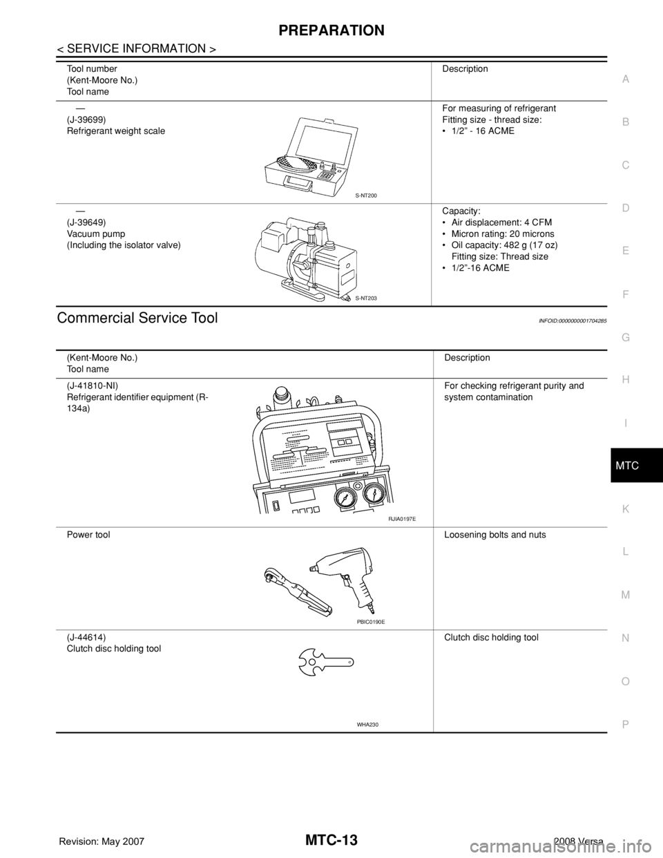
Commercial Service ToolINFOID:0000000001704285
—
(J-39699)
Refrigerant weight scaleFor measuring of refrigerant
Fitting size - thread size:
• 1/2” - 16 ACME
—
(J-39649)
Va c u u m p u m p
(Including the isolator valve)Capacity:
• Air displacement: 4 CFM
• Micron rating: 20 microns
• Oil capacity: 482 g (17 oz)
Fitting size: Thread size
• 1/2”-16 ACME Tool number
(Kent-Moore No.)
Tool nameDescription
S-NT200
S-NT203
(Kent-Moore No.)
Tool nameDescription
(J-41810-NI)
Refrigerant identifier equipment (R-
134a)For checking refrigerant purity and
system contamination
Power toolLoosening bolts and nuts
(J-44614)
Clutch disc holding toolClutch disc holding tool
RJIA0197E
PBIC0190E
WHA230
Page 2352 of 2771
MTC-14
< SERVICE INFORMATION >
REFRIGERATION SYSTEM
REFRIGERATION SYSTEM
Refrigerant CycleINFOID:0000000001704286
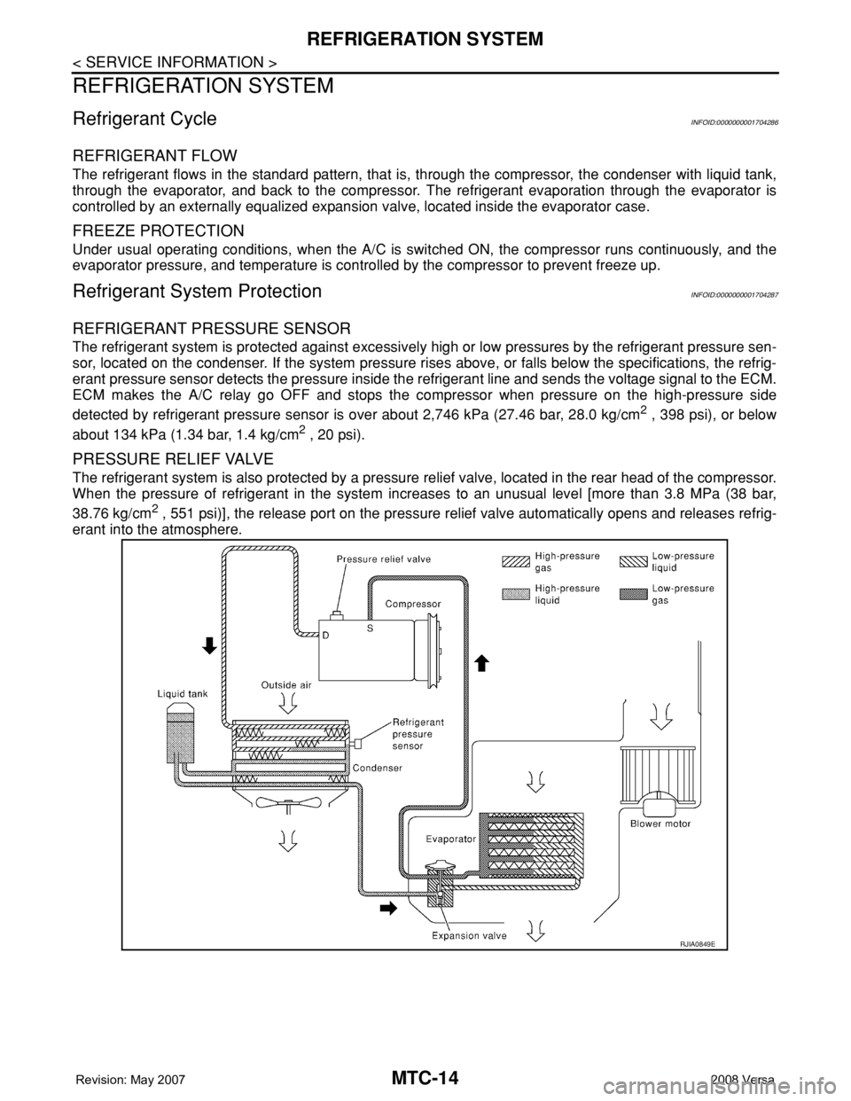
REFRIGERANT FLOW
The refrigerant flows in the standard pattern, that is, through the compressor, the condenser with liquid tank,
through the evaporator, and back to the compressor. The refrigerant evaporation through the evaporator is
controlled by an externally equalized expansion valve, located inside the evaporator case.
FREEZE PROTECTION
Under usual operating conditions, when the A/C is switched ON, the compressor runs continuously, and the
evaporator pressure, and temperature is controlled by the compressor to prevent freeze up.
Refrigerant System ProtectionINFOID:0000000001704287
REFRIGERANT PRESSURE SENSOR
The refrigerant system is protected against excessively high or low pressures by the refrigerant pressure sen-
sor, located on the condenser. If the system pressure rises above, or falls below the specifications, the refrig-
erant pressure sensor detects the pressure inside the refrigerant line and sends the voltage signal to the ECM.
ECM makes the A/C relay go OFF and stops the compressor when pressure on the high-pressure side
detected by refrigerant pressure sensor is over about 2,746 kPa (27.46 bar, 28.0 kg/cm
2 , 398 psi), or below
about 134 kPa (1.34 bar, 1.4 kg/cm
2 , 20 psi).
PRESSURE RELIEF VALVE
The refrigerant system is also protected by a pressure relief valve, located in the rear head of the compressor.
When the pressure of refrigerant in the system increases to an unusual level [more than 3.8 MPa (38 bar,
38.76 kg/cm
2 , 551 psi)], the release port on the pressure relief valve automatically opens and releases refrig-
erant into the atmosphere.
RJIA0849E
Page 2353 of 2771
REFRIGERATION SYSTEM
MTC-15
< SERVICE INFORMATION >
C
D
E
F
G
H
I
K
L
MA
B
MTC
N
O
P
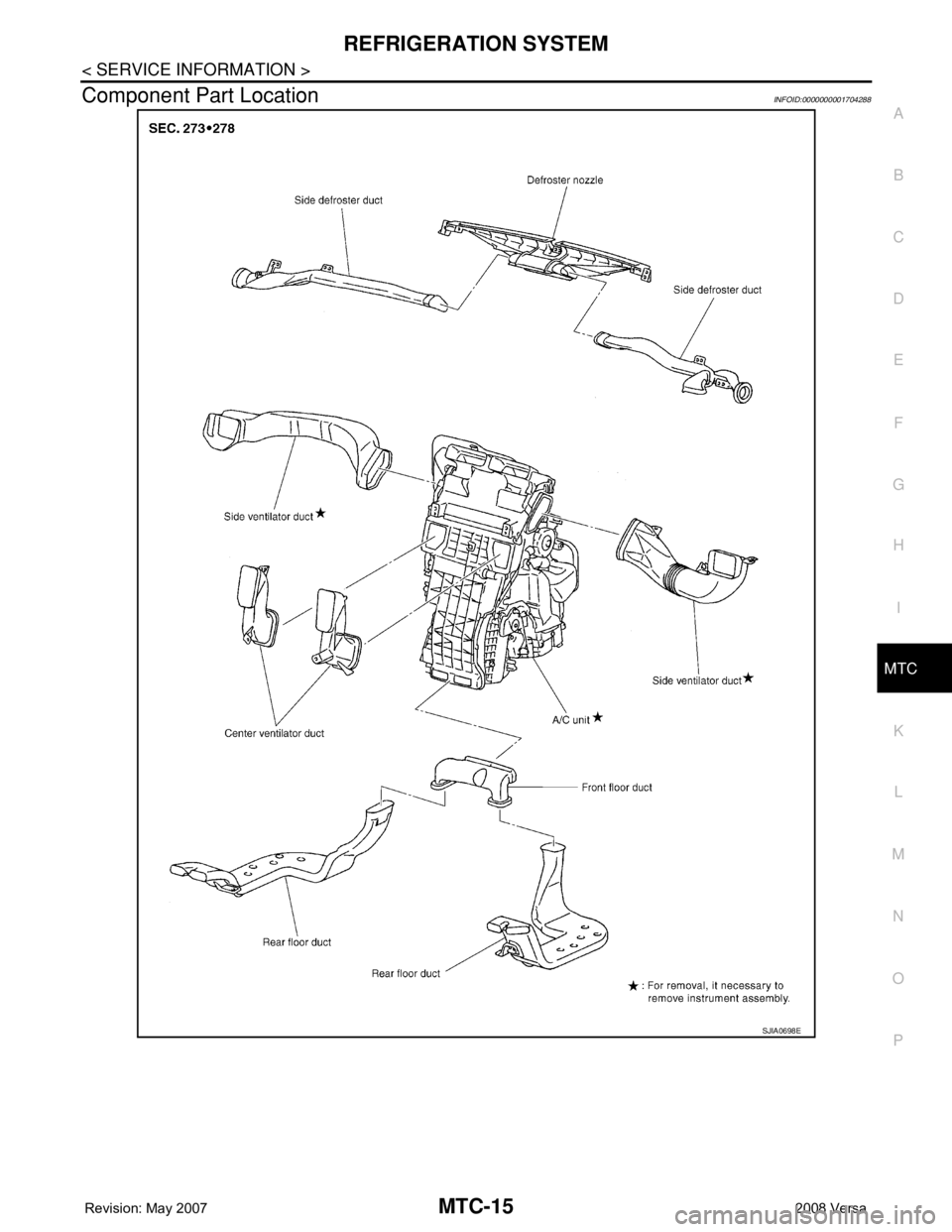
Component Part LocationINFOID:0000000001704288
SJIA0698E
Page 2354 of 2771
MTC-16
< SERVICE INFORMATION >
OIL
OIL
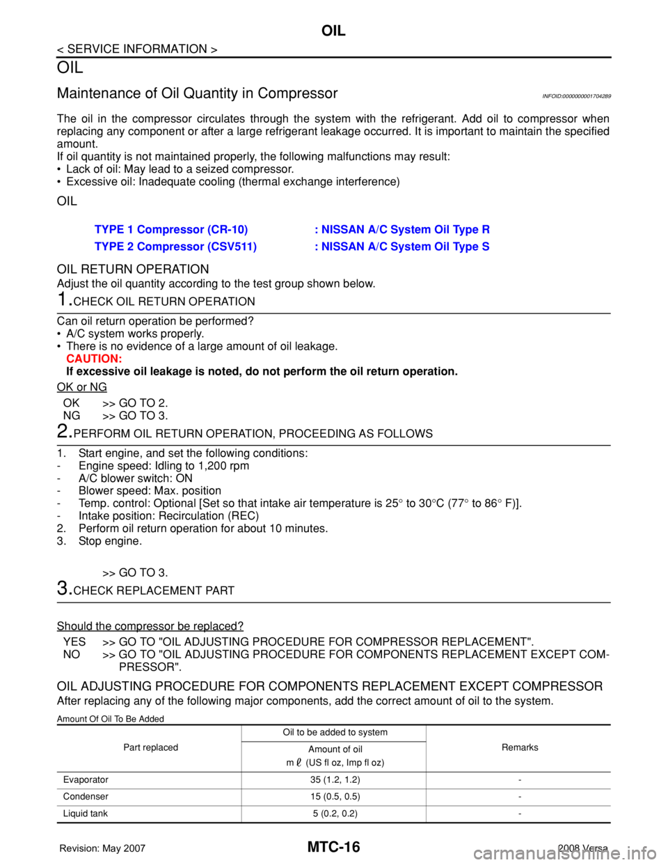
Maintenance of Oil Quantity in CompressorINFOID:0000000001704289
The oil in the compressor circulates through the system with the refrigerant. Add oil to compressor when
replacing any component or after a large refrigerant leakage occurred. It is important to maintain the specified
amount.
If oil quantity is not maintained properly, the following malfunctions may result:
• Lack of oil: May lead to a seized compressor.
• Excessive oil: Inadequate cooling (thermal exchange interference)
OIL
OIL RETURN OPERATION
Adjust the oil quantity according to the test group shown below.
1.CHECK OIL RETURN OPERATION
Can oil return operation be performed?
• A/C system works properly.
• There is no evidence of a large amount of oil leakage.
CAUTION:
If excessive oil leakage is noted, do not perform the oil return operation.
OK or NG
OK >> GO TO 2.
NG >> GO TO 3.
2.PERFORM OIL RETURN OPERATION, PROCEEDING AS FOLLOWS
1. Start engine, and set the following conditions:
- Engine speed: Idling to 1,200 rpm
- A/C blower switch: ON
- Blower speed: Max. position
- Temp. control: Optional [Set so that intake air temperature is 25° to 30°C (77° to 86° F)].
- Intake position: Recirculation (REC)
2. Perform oil return operation for about 10 minutes.
3. Stop engine.
>> GO TO 3.
3.CHECK REPLACEMENT PART
Should the compressor be replaced?
YES >> GO TO "OIL ADJUSTING PROCEDURE FOR COMPRESSOR REPLACEMENT".
NO >> GO TO "OIL ADJUSTING PROCEDURE FOR COMPONENTS REPLACEMENT EXCEPT COM-
PRESSOR".
OIL ADJUSTING PROCEDURE FOR COMPONENTS REPLACEMENT EXCEPT COMPRESSOR
After replacing any of the following major components, add the correct amount of oil to the system.
Amount Of Oil To Be Added
TYPE 1 Compressor (CR-10) : NISSAN A/C System Oil Type R
TYPE 2 Compressor (CSV511) : NISSAN A/C System Oil Type S
Part replacedOil to be added to system
Remarks
Amount of oil
m (US fl oz, Imp fl oz)
Evaporator 35 (1.2, 1.2) -
Condenser 15 (0.5, 0.5) -
Liquid tank 5 (0.2, 0.2) -
Page 2355 of 2771
OIL
MTC-17
< SERVICE INFORMATION >
C
D
E
F
G
H
I
K
L
MA
B
MTC
N
O
P
*1: If refrigerant leak is small, no addition of oil is needed.
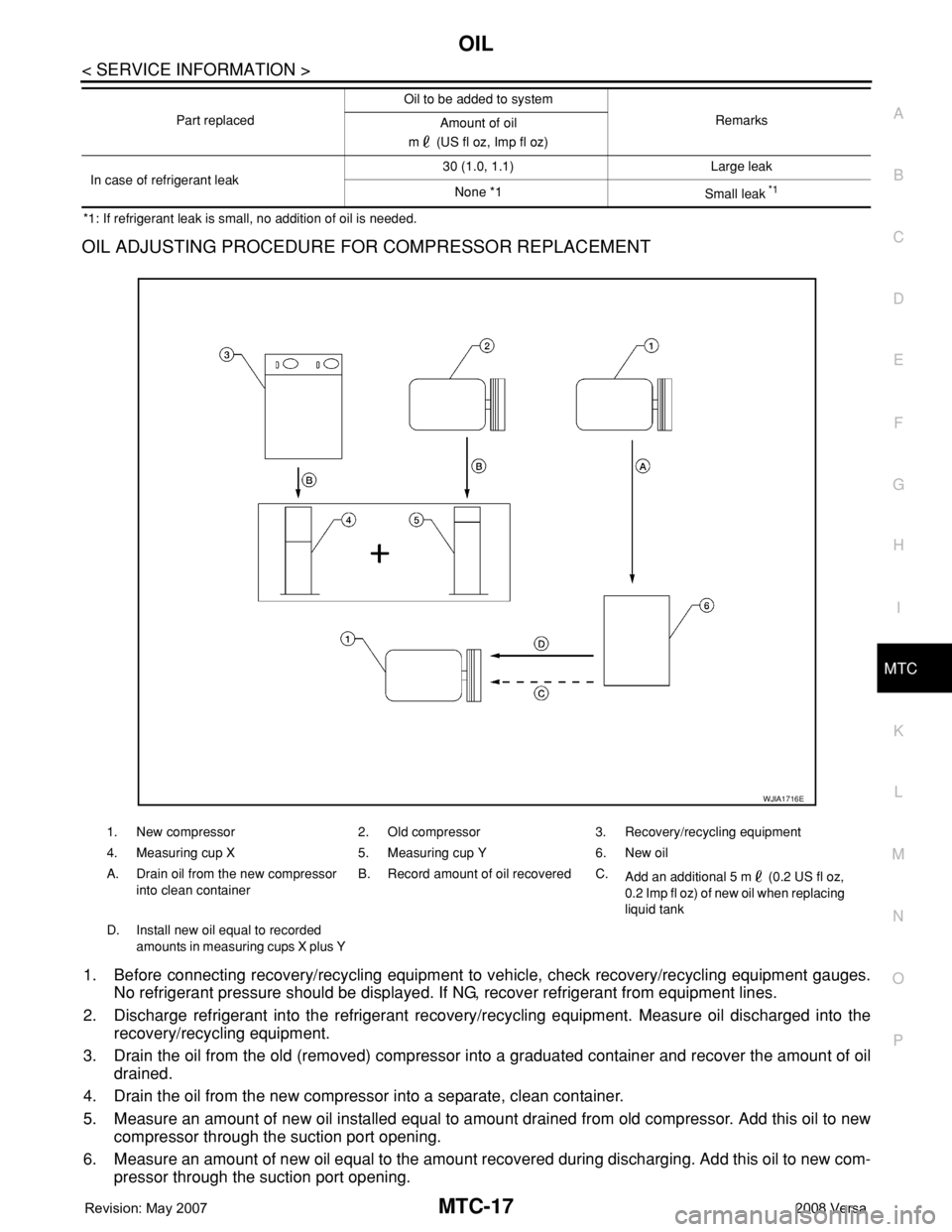
OIL ADJUSTING PROCEDURE FOR COMPRESSOR REPLACEMENT
1. Before connecting recovery/recycling equipment to vehicle, check recovery/recycling equipment gauges.
No refrigerant pressure should be displayed. If NG, recover refrigerant from equipment lines.
2. Discharge refrigerant into the refrigerant recovery/recycling equipment. Measure oil discharged into the
recovery/recycling equipment.
3. Drain the oil from the old (removed) compressor into a graduated container and recover the amount of oil
drained.
4. Drain the oil from the new compressor into a separate, clean container.
5. Measure an amount of new oil installed equal to amount drained from old compressor. Add this oil to new
compressor through the suction port opening.
6. Measure an amount of new oil equal to the amount recovered during discharging. Add this oil to new com-
pressor through the suction port opening.
In case of refrigerant leak30 (1.0, 1.1) Large leak
None *1
Small leak *1
Part replacedOil to be added to system
Remarks
Amount of oil
m (US fl oz, Imp fl oz)
1. New compressor 2. Old compressor 3. Recovery/recycling equipment
4. Measuring cup X 5. Measuring cup Y 6. New oil
A. Drain oil from the new compressor
into clean containerB. Record amount of oil recovered C.
Add an additional 5 m (0.2 US fl oz,
0.2 Imp fl oz) of new oil when replacing
liquid tank
D. Install new oil equal to recorded
amounts in measuring cups X plus Y
WJIA1716E
Page 2356 of 2771

MTC-18
< SERVICE INFORMATION >
OIL
7. If the liquid tank also needs to be replaced, add another 5 m (0.2 US fl oz, 0.2 Imp fl oz.) of oil at this
time.
Add this 5 m (0.2 US fl oz, 0.2 Imp fl oz.) of oil only when replacing the compressor.
Page 2357 of 2771
AIR CONDITIONER CONTROL
MTC-19
< SERVICE INFORMATION >
C
D
E
F
G
H
I
K
L
MA
B
MTC
N
O
P
AIR CONDITIONER CONTROL
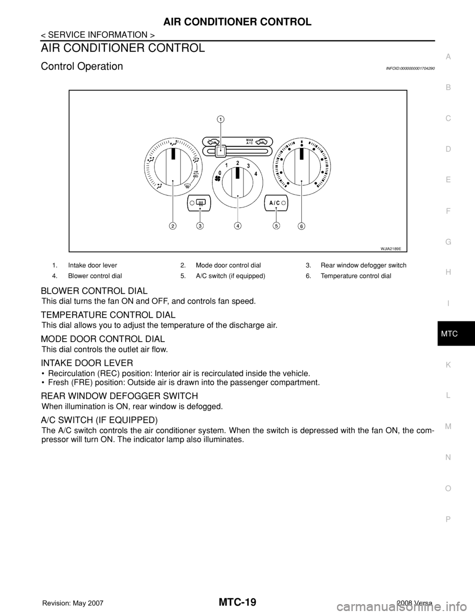
Control OperationINFOID:0000000001704290
BLOWER CONTROL DIAL
This dial turns the fan ON and OFF, and controls fan speed.
TEMPERATURE CONTROL DIAL
This dial allows you to adjust the temperature of the discharge air.
MODE DOOR CONTROL DIAL
This dial controls the outlet air flow.
INTAKE DOOR LEVER
• Recirculation (REC) position: Interior air is recirculated inside the vehicle.
• Fresh (FRE) position: Outside air is drawn into the passenger compartment.
REAR WINDOW DEFOGGER SWITCH
When illumination is ON, rear window is defogged.
A/C SWITCH (IF EQUIPPED)
The A/C switch controls the air conditioner system. When the switch is depressed with the fan ON, the com-
pressor will turn ON. The indicator lamp also illuminates.
1. Intake door lever 2. Mode door control dial 3. Rear window defogger switch
4. Blower control dial 5. A/C switch (if equipped) 6. Temperature control dial
WJIA2189E
Page 2358 of 2771
MTC-20
< SERVICE INFORMATION >
AIR CONDITIONER CONTROL
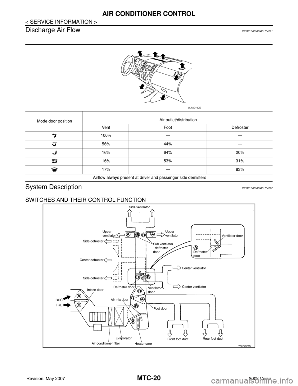
Discharge Air Flow
INFOID:0000000001704291
System DescriptionINFOID:0000000001704292
SWITCHES AND THEIR CONTROL FUNCTION
Mode door positionAir outlet/distribution
Vent Foot Defroster
100% — —
56% 44% —
16% 64% 20%
16% 53% 31%
17% — 83%
Airflow always present at driver and passenger side demisters
WJIA2190E
WJIA2249E
Page 2359 of 2771
AIR CONDITIONER CONTROL
MTC-21
< SERVICE INFORMATION >
C
D
E
F
G
H
I
K
L
MA
B
MTC
N
O
P
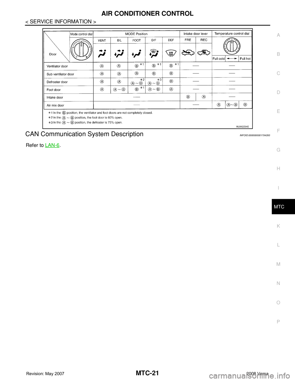
CAN Communication System DescriptionINFOID:0000000001704293
Refer to LAN-6.
WJIA2234E
Page 2360 of 2771
MTC-22
< SERVICE INFORMATION >
TROUBLE DIAGNOSIS
TROUBLE DIAGNOSIS
CONSULT-III Function (BCM)INFOID:0000000001704294
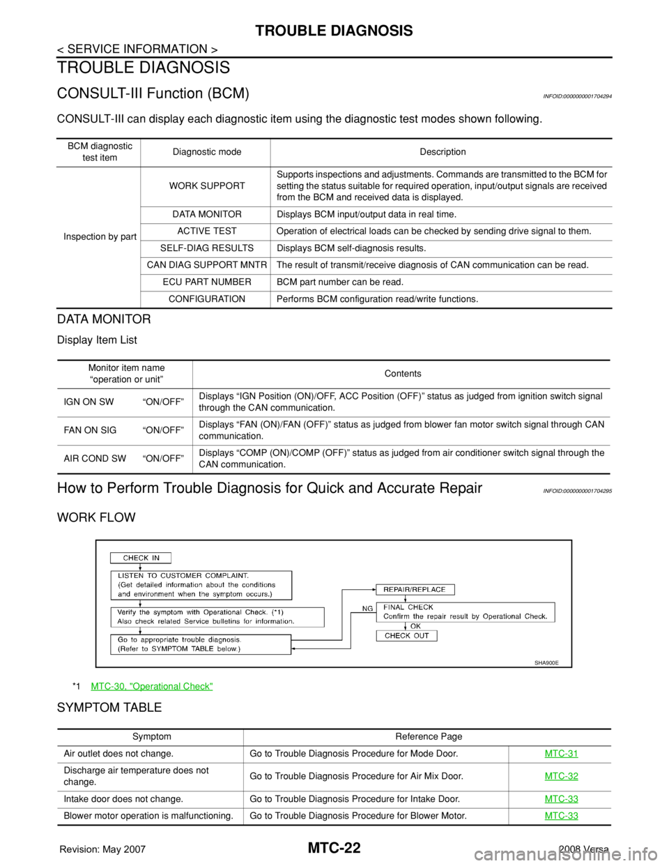
CONSULT-III can display each diagnostic item using the diagnostic test modes shown following.
DATA MONITOR
Display Item List
How to Perform Trouble Diagnosis for Quick and Accurate RepairINFOID:0000000001704295
WORK FLOW
SYMPTOM TABLE
BCM diagnostic
test itemDiagnostic mode Description
Inspection by partWORK SUPPORTSupports inspections and adjustments. Commands are transmitted to the BCM for
setting the status suitable for required operation, input/output signals are received
from the BCM and received data is displayed.
DATA MONITOR Displays BCM input/output data in real time.
ACTIVE TEST Operation of electrical loads can be checked by sending drive signal to them.
SELF-DIAG RESULTS Displays BCM self-diagnosis results.
CAN DIAG SUPPORT MNTR The result of transmit/receive diagnosis of CAN communication can be read.
ECU PART NUMBER BCM part number can be read.
CONFIGURATION Performs BCM configuration read/write functions.
Monitor item name
“operation or unit”Contents
IGN ON SW “ON/OFF”Displays “IGN Position (ON)/OFF, ACC Position (OFF)” status as judged from ignition switch signal
through the CAN communication.
FAN ON SIG “ON/OFF”Displays “FAN (ON)/FAN (OFF)” status as judged from blower fan motor switch signal through CAN
communication.
AIR COND SW “ON/OFF”Displays “COMP (ON)/COMP (OFF)” status as judged from air conditioner switch signal through the
CAN communication.
*1MTC-30, "Operational Check"
SHA900E
Symptom Reference Page
Air outlet does not change. Go to Trouble Diagnosis Procedure for Mode Door.MTC-31
Discharge air temperature does not
change.Go to Trouble Diagnosis Procedure for Air Mix Door.MTC-32
Intake door does not change. Go to Trouble Diagnosis Procedure for Intake Door.MTC-33
Blower motor operation is malfunctioning. Go to Trouble Diagnosis Procedure for Blower Motor.MTC-33