Transaxle Assembly NISSAN TIIDA 2008 Service Owner's Manual
[x] Cancel search | Manufacturer: NISSAN, Model Year: 2008, Model line: TIIDA, Model: NISSAN TIIDA 2008Pages: 2771, PDF Size: 60.61 MB
Page 241 of 2771

TRANSAXLE ASSEMBLY
AT-229
< SERVICE INFORMATION >
D
E
F
G
H
I
J
K
L
MA
B
AT
N
O
P
• Align the positions for the bolts on drive plate with those of the
torque converter, and temporarily tighten bolts. Then, tighten bolts
to the specified torque.
• After completing installation, check for A/T fluid leakage, A/T fluid
level and A/T positions. Refer to MA-22, "
Checking A/T Fluid" and
AT-207, "
Checking of A/T Position". Converter nuts : 51 N·m (5.2 kg-m, 38 ft-lb)
WCIA0616E
Page 247 of 2771

OVERHAUL
AT-235
< SERVICE INFORMATION >
D
E
F
G
H
I
J
K
L
MA
B
AT
N
O
P
1. Snap ring 2. Governor cap 3. O-ring
4. Lock nut 5. Anchor end pin 6. Transaxle case
7. Reduction pinion gear bearing 8. Reduction pinion gear 9. Brake band
10. Snap ring 11. Radial needle bearing 12. Seal ring
13. Bearing retainer 14. O-ring 15. Servo release accumulator piston
16. Return spring 17. Control valve assembly 18. Oil pan gasket
SCIA7959E
Page 253 of 2771
DISASSEMBLY
AT-241
< SERVICE INFORMATION >
D
E
F
G
H
I
J
K
L
MA
B
AT
N
O
P
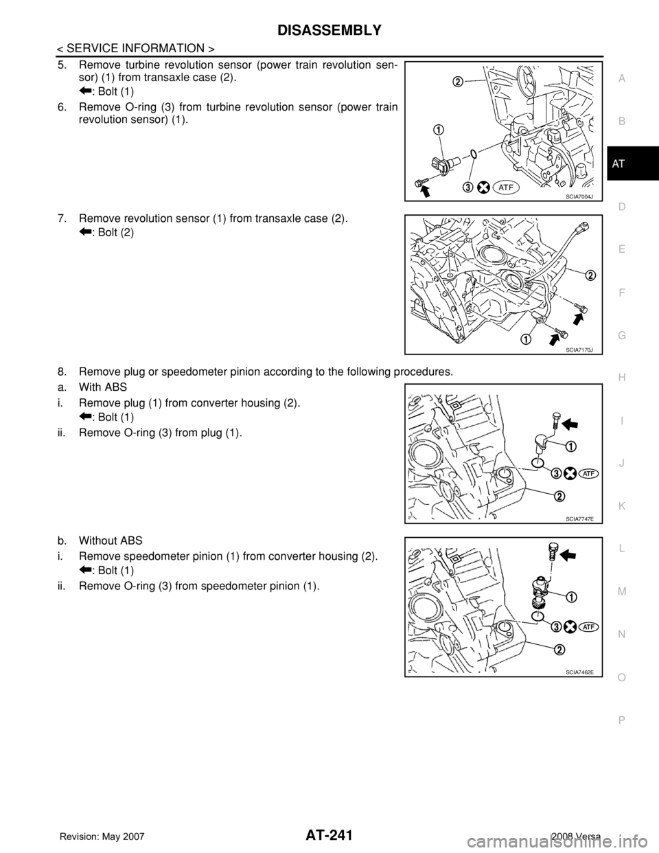
5. Remove turbine revolution sensor (power train revolution sen-
sor) (1) from transaxle case (2).
: Bolt (1)
6. Remove O-ring (3) from turbine revolution sensor (power train
revolution sensor) (1).
7. Remove revolution sensor (1) from transaxle case (2).
: Bolt (2)
8. Remove plug or speedometer pinion according to the following procedures.
a. With ABS
i. Remove plug (1) from converter housing (2).
: Bolt (1)
ii. Remove O-ring (3) from plug (1).
b. Without ABS
i. Remove speedometer pinion (1) from converter housing (2).
: Bolt (1)
ii. Remove O-ring (3) from speedometer pinion (1).
SCIA7004J
SCIA7170J
SCIA7747E
SCIA7462E
Page 254 of 2771
AT-242
< SERVICE INFORMATION >
DISASSEMBLY
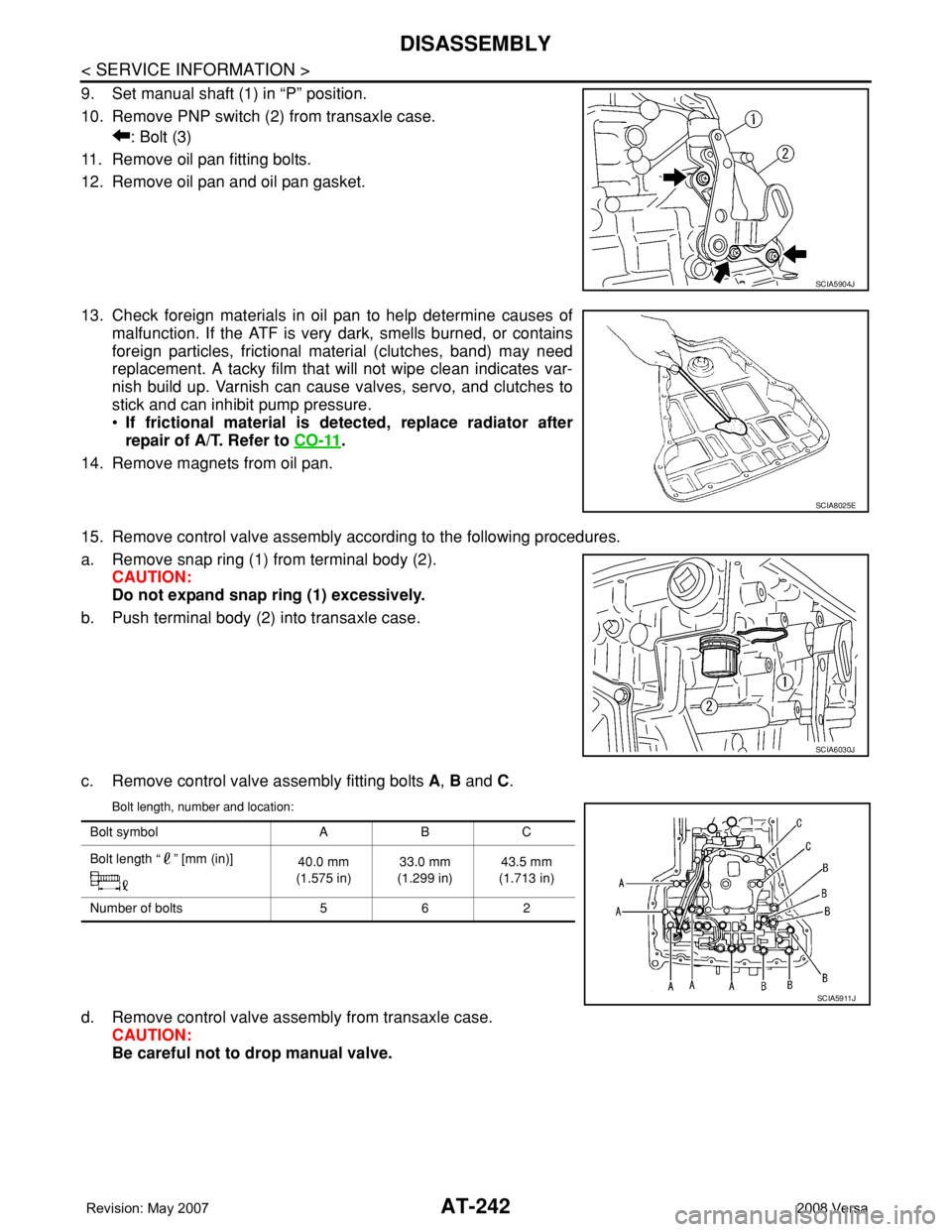
9. Set manual shaft (1) in “P” position.
10. Remove PNP switch (2) from transaxle case.
: Bolt (3)
11. Remove oil pan fitting bolts.
12. Remove oil pan and oil pan gasket.
13. Check foreign materials in oil pan to help determine causes of
malfunction. If the ATF is very dark, smells burned, or contains
foreign particles, frictional material (clutches, band) may need
replacement. A tacky film that will not wipe clean indicates var-
nish build up. Varnish can cause valves, servo, and clutches to
stick and can inhibit pump pressure.
•If frictional material is detected, replace radiator after
repair of A/T. Refer to CO-11
.
14. Remove magnets from oil pan.
15. Remove control valve assembly according to the following procedures.
a. Remove snap ring (1) from terminal body (2).
CAUTION:
Do not expand snap ring (1) excessively.
b. Push terminal body (2) into transaxle case.
c. Remove control valve assembly fitting bolts A, B and C.
Bolt length, number and location:
d. Remove control valve assembly from transaxle case.
CAUTION:
Be careful not to drop manual valve.
SCIA5904J
SCIA8025E
SCIA6030J
Bolt symbol A B C
Bolt length “ ” [mm (in)]
40.0 mm
(1.575 in)33.0 mm
(1.299 in)43.5 mm
(1.713 in)
Number of bolts 5 6 2
SCIA5911J
Page 255 of 2771
DISASSEMBLY
AT-243
< SERVICE INFORMATION >
D
E
F
G
H
I
J
K
L
MA
B
AT
N
O
P
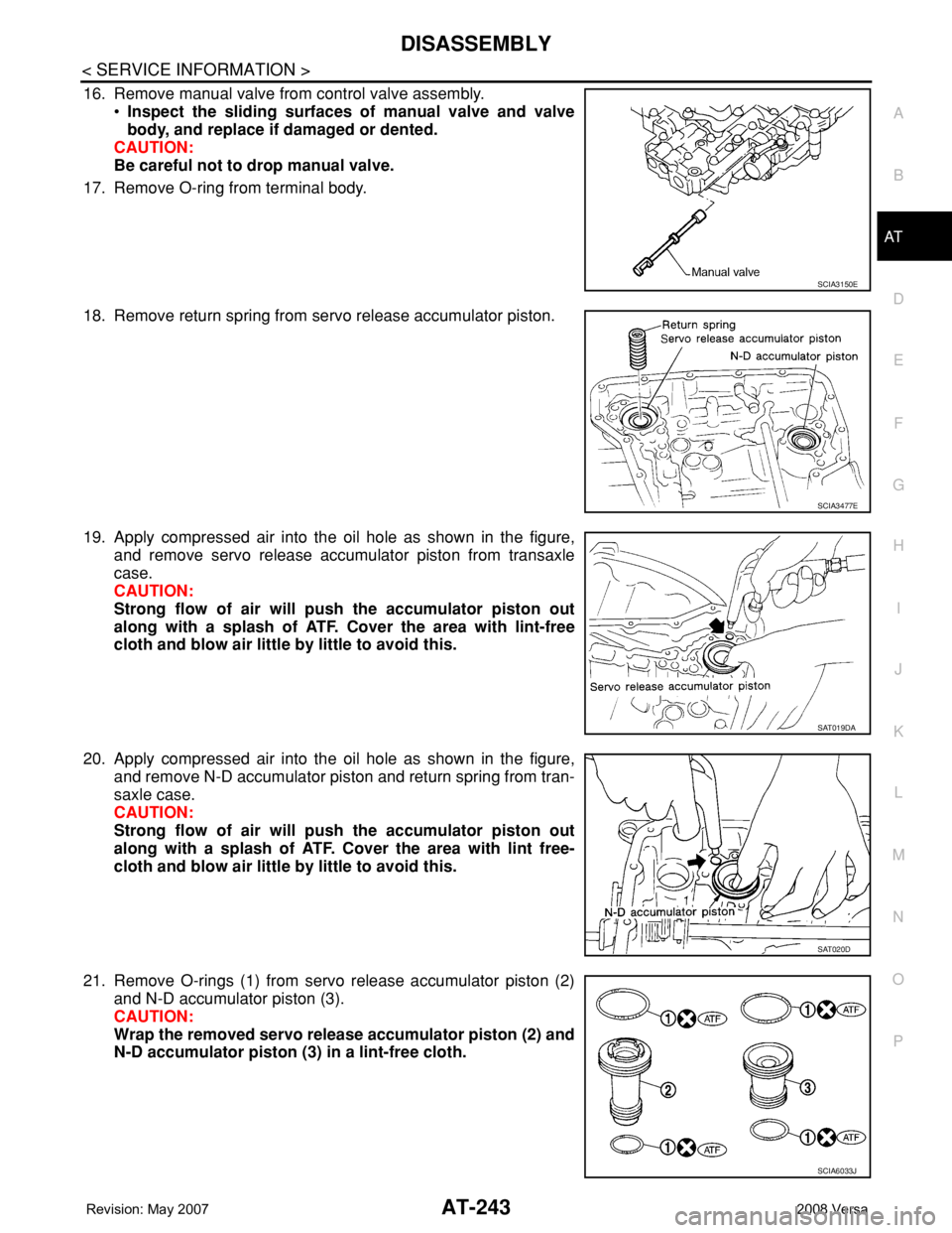
16. Remove manual valve from control valve assembly.
•Inspect the sliding surfaces of manual valve and valve
body, and replace if damaged or dented.
CAUTION:
Be careful not to drop manual valve.
17. Remove O-ring from terminal body.
18. Remove return spring from servo release accumulator piston.
19. Apply compressed air into the oil hole as shown in the figure,
and remove servo release accumulator piston from transaxle
case.
CAUTION:
Strong flow of air will push the accumulator piston out
along with a splash of ATF. Cover the area with lint-free
cloth and blow air little by little to avoid this.
20. Apply compressed air into the oil hole as shown in the figure,
and remove N-D accumulator piston and return spring from tran-
saxle case.
CAUTION:
Strong flow of air will push the accumulator piston out
along with a splash of ATF. Cover the area with lint free-
cloth and blow air little by little to avoid this.
21. Remove O-rings (1) from servo release accumulator piston (2)
and N-D accumulator piston (3).
CAUTION:
Wrap the removed servo release accumulator piston (2) and
N-D accumulator piston (3) in a lint-free cloth.
SCIA3150E
SCIA3477E
SAT019DA
SAT020D
SCIA6033J
Page 256 of 2771

AT-244
< SERVICE INFORMATION >
DISASSEMBLY
•Inspect the sliding surfaces of each accumulator piston and
transaxle case, and replace if damaged or dented.
(1): Servo release accumulator piston
(2): N-D accumulator piston
• Inspect each return spring, and replace if deformed or worn. Refer
to AT-343, "
Accumulator" for free length (L1) and length (L2).
(1): Return spring (Servo release accumulator)
(2): Return spring (N-D accumulator)
CAUTION:
Do not remove spring retainer (3).
22. Remove lip seals (1) from transaxle case.
23. Remove converter housing according to the following procedures.
SCIA6035J
SCIA6955E
SCIA5895J
Page 257 of 2771
DISASSEMBLY
AT-245
< SERVICE INFORMATION >
D
E
F
G
H
I
J
K
L
MA
B
AT
N
O
P
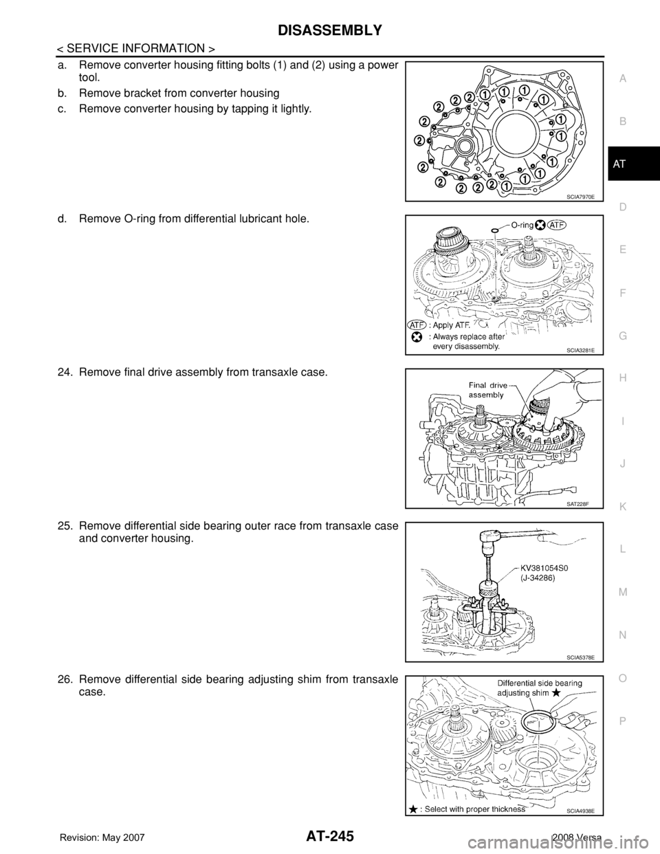
a. Remove converter housing fitting bolts (1) and (2) using a power
tool.
b. Remove bracket from converter housing
c. Remove converter housing by tapping it lightly.
d. Remove O-ring from differential lubricant hole.
24. Remove final drive assembly from transaxle case.
25. Remove differential side bearing outer race from transaxle case
and converter housing.
26. Remove differential side bearing adjusting shim from transaxle
case.
SCIA7970E
SCIA3281E
SAT228F
SCIA5378E
SCIA4938E
Page 258 of 2771

AT-246
< SERVICE INFORMATION >
DISASSEMBLY
27. Remove RH differential side oil seal from converter housing
using a flat-bladed screwdriver.
CAUTION:
Be careful not to scratch converter housing.
28. Remove differential lubricant tube (1) and clips (2) from con-
verter housing.
: Bolt (3)
29. Remove oil pump assembly according to the following procedures.
a. Remove O-ring from input shaft assembly (high clutch drum).
b. Remove oil pump assembly fitting bolts, and then remove oil
pump assembly (1) from transaxle case.
c. Remove O-ring from oil pump assembly (1).
SCIA3283E
SCIA7817E
SCIA5634E
SCIA6036J
Page 259 of 2771

DISASSEMBLY
AT-247
< SERVICE INFORMATION >
D
E
F
G
H
I
J
K
L
MA
B
AT
N
O
P
d. Remove bearing race (1) and thrust washer (2) from oil pump
assembly (3).
30. Remove brake band according to the following procedures.
a. Loosen lock nut (1), and then remove anchor end pin (2) and
lock nut (1) as a set from transaxle case.
b. Remove brake band from transaxle case.
•To prevent brake linings from cracking or peeling, do not
stretch the flexible band unnecessarily. When removing
brake band, always secure it with a clip as shown in the
figure.
Leave the clip in position after removing brake band.
SCIA6957E
SCIA6037J
SAT038D
SAT039D
Page 262 of 2771
AT-250
< SERVICE INFORMATION >
DISASSEMBLY
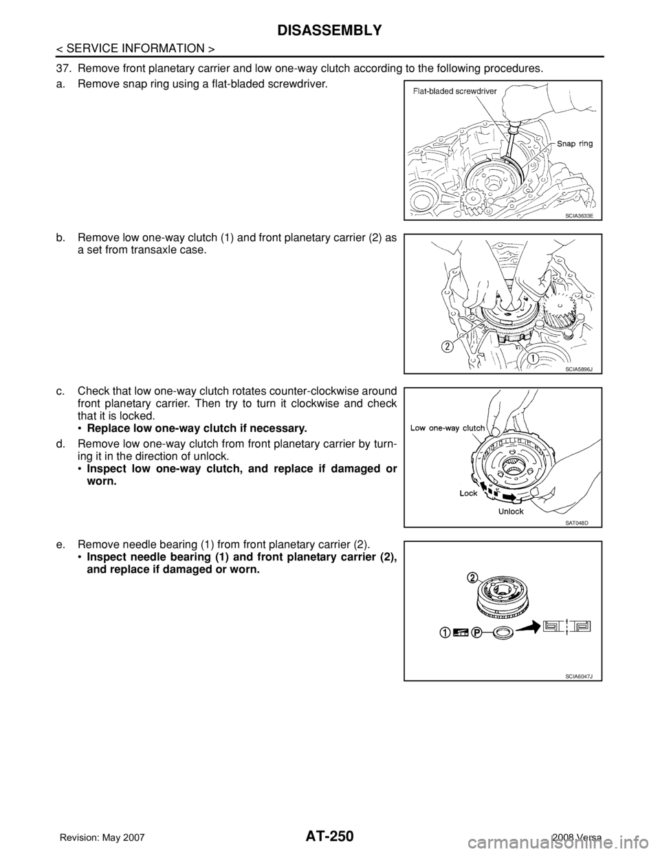
37. Remove front planetary carrier and low one-way clutch according to the following procedures.
a. Remove snap ring using a flat-bladed screwdriver.
b. Remove low one-way clutch (1) and front planetary carrier (2) as
a set from transaxle case.
c. Check that low one-way clutch rotates counter-clockwise around
front planetary carrier. Then try to turn it clockwise and check
that it is locked.
•Replace low one-way clutch if necessary.
d. Remove low one-way clutch from front planetary carrier by turn-
ing it in the direction of unlock.
•Inspect low one-way clutch, and replace if damaged or
worn.
e. Remove needle bearing (1) from front planetary carrier (2).
•Inspect needle bearing (1) and front planetary carrier (2),
and replace if damaged or worn.
SCIA3633E
SCIA5896J
SAT048D
SCIA6047J