Transaxle Assembly NISSAN TIIDA 2008 Service Manual PDF
[x] Cancel search | Manufacturer: NISSAN, Model Year: 2008, Model line: TIIDA, Model: NISSAN TIIDA 2008Pages: 2771, PDF Size: 60.61 MB
Page 351 of 2771
ASSEMBLY
AT-339
< SERVICE INFORMATION >
D
E
F
G
H
I
J
K
L
MA
B
AT
N
O
P
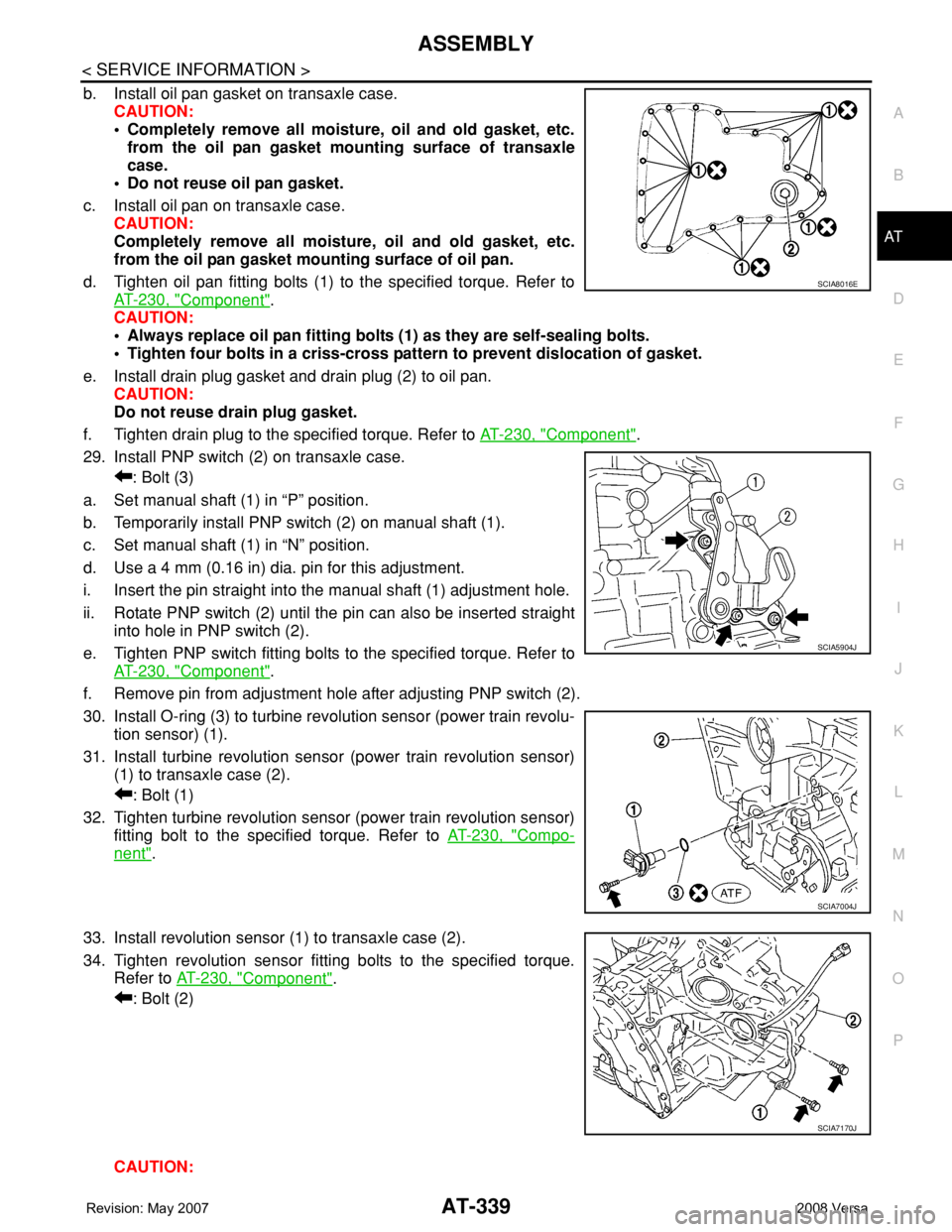
b. Install oil pan gasket on transaxle case.
CAUTION:
• Completely remove all moisture, oil and old gasket, etc.
from the oil pan gasket mounting surface of transaxle
case.
• Do not reuse oil pan gasket.
c. Install oil pan on transaxle case.
CAUTION:
Completely remove all moisture, oil and old gasket, etc.
from the oil pan gasket mounting surface of oil pan.
d. Tighten oil pan fitting bolts (1) to the specified torque. Refer to
AT-230, "
Component".
CAUTION:
• Always replace oil pan fitting bolts (1) as they are self-sealing bolts.
• Tighten four bolts in a criss-cross pattern to prevent dislocation of gasket.
e. Install drain plug gasket and drain plug (2) to oil pan.
CAUTION:
Do not reuse drain plug gasket.
f. Tighten drain plug to the specified torque. Refer to AT-230, "
Component".
29. Install PNP switch (2) on transaxle case.
: Bolt (3)
a. Set manual shaft (1) in “P” position.
b. Temporarily install PNP switch (2) on manual shaft (1).
c. Set manual shaft (1) in “N” position.
d. Use a 4 mm (0.16 in) dia. pin for this adjustment.
i. Insert the pin straight into the manual shaft (1) adjustment hole.
ii. Rotate PNP switch (2) until the pin can also be inserted straight
into hole in PNP switch (2).
e. Tighten PNP switch fitting bolts to the specified torque. Refer to
AT-230, "
Component".
f. Remove pin from adjustment hole after adjusting PNP switch (2).
30. Install O-ring (3) to turbine revolution sensor (power train revolu-
tion sensor) (1).
31. Install turbine revolution sensor (power train revolution sensor)
(1) to transaxle case (2).
: Bolt (1)
32. Tighten turbine revolution sensor (power train revolution sensor)
fitting bolt to the specified torque. Refer to AT-230, "
Compo-
nent".
33. Install revolution sensor (1) to transaxle case (2).
34. Tighten revolution sensor fitting bolts to the specified torque.
Refer to AT-230, "
Component".
: Bolt (2)
CAUTION:
SCIA8016E
SCIA5904J
SCIA7004J
SCIA7170J
Page 353 of 2771

SERVICE DATA AND SPECIFICATIONS (SDS)
AT-341
< SERVICE INFORMATION >
D
E
F
G
H
I
J
K
L
MA
B
AT
N
O
P
SERVICE DATA AND SPECIFICATIONS (SDS)
General SpecificationINFOID:0000000001703396
*: Refer to MA-10.
Vehicle Speed at Which Gear Shifting OccursINFOID:0000000001703397
• At half throttle, the accelerator opening is 4/8 of the full opening.
Vehicle Speed at When Lock-up Occurs/ReleasesINFOID:0000000001703398
Stall SpeedINFOID:0000000001703399
Line PressureINFOID:0000000001703400
Adjusting shims, Needle Bearings, Thrust Washers and Snap RingsINFOID:0000000001703401
NOTE:
EngineMR18DE
Automatic transaxle model RE4F03B
Automatic transaxle assembly Model code number 3CX0D
Transaxle gear ratio1st 2.861
2nd 1.562
3rd 1.000
4th 0.697
Reverse 2.310
Final drive 4.072
Recommended fluidGenuine NISSAN Matic D ATF (Continental U.S. and Alaska) or
Canada NISSAN Automatic Transmission Fluid*
Fluid capacity [ (US qt, Imp qt)]7.9 (8-3/8, 7)
Throttle positionVehicle speed km/h (MPH)
D1 → D2D2 → D3D3 → D4D4 → D3D3 → D2D2 → D1
Full throttle51 - 59
(32 - 37)97 - 105
(60 - 65)154 - 162
(96 - 101)150 - 158
(93 - 98)87 - 95
(54 - 59)40 - 48
(25 - 30)
Half throttle34 - 42
(21 - 26)62 - 70
(39 - 43)124 - 132
(77 - 82)69 - 77
(43 - 48)36 - 44
(22 - 27)19 - 27
(12 - 17)
Throttle position Selector lever positionVehicle speed km/h (MPH)
Lock-up ON Lock-up OFF
2.0/8“D” position 86 - 94 (53 - 58) 59 - 67 (37 - 42)
“D” position (OD OFF) 86 - 94 (53 - 58) 83 - 91 (52 - 57)
Stall revolution (rpm)2,310 - 2,770
Engine speedLine pressure kPa (kg/cm2, psi)
“D”, “2” and “1” positions “R” position
Idle speed 500 (5.1, 73) 778 (7.9, 113)
Stall speed 1,173 (12.0, 170) 1,825 (18.6, 265)
Page 803 of 2771

CL-2
< SERVICE INFORMATION >
PRECAUTIONS
SERVICE INFORMATION
PRECAUTIONS
Precaution for Supplemental Restraint System (SRS) "AIR BAG" and "SEAT BELT
PRE-TENSIONER"
INFOID:0000000001703112
The Supplemental Restraint System such as “AIR BAG” and “SEAT BELT PRE-TENSIONER”, used along
with a front seat belt, helps to reduce the risk or severity of injury to the driver and front passenger for certain
types of collision. This system includes seat belt switch inputs and dual stage front air bag modules. The SRS
system uses the seat belt switches to determine the front air bag deployment, and may only deploy one front
air bag, depending on the severity of a collision and whether the front occupants are belted or unbelted.
Information necessary to service the system safely is included in the SRS and SB section of this Service Man-
ual.
WARNING:
• To avoid rendering the SRS inoperative, which could increase the risk of personal injury or death in
the event of a collision which would result in air bag inflation, all maintenance must be performed by
an authorized NISSAN/INFINITI dealer.
• Improper maintenance, including incorrect removal and installation of the SRS, can lead to personal
injury caused by unintentional activation of the system. For removal of Spiral Cable and Air Bag
Module, see the SRS section.
• Do not use electrical test equipment on any circuit related to the SRS unless instructed to in this
Service Manual. SRS wiring harnesses can be identified by yellow and/or orange harnesses or har-
ness connectors.
Precaution for Procedure without Cowl Top CoverINFOID:0000000001843684
When performing the procedure after removing cowl top cover, cover
the lower end of windshield with urethane, etc.
Service Notice or PrecautionINFOID:0000000001703113
•Use recommended brake fluid when adding fluid to the clutch reservoir tank. Refer to MA-10.
•Never reuse fluid drained from clutch system.
•Be careful not to splash brake fluid on painted areas.
•Use new brake fluid to clean or wash all parts of master cylinder and operating cylinder.
•Never use mineral oils such as gasoline or kerosene. It will ruin the rubber parts of the hydraulic sys-
tem.
•If transaxle assembly is removed from the vehicle, always replace CSC (Concentric slave cylinder).
Return CSC to original position to remove transaxle assembly. Dust on clutch disc sliding parts may
damage CSC seal and may cause clutch fluid leakage.
•Do not disassemble clutch master cylinder and CSC.
WARNING:
After cleaning clutch disc, clean it with a dust collector. Do not use compressed air.
PIIB3706J
Page 812 of 2771

CSC (CONCENTRIC SLAVE CYLINDER)
CL-11
< SERVICE INFORMATION >
D
E
F
G
H
I
J
K
L
MA
B
CL
N
O
P
CSC (CONCENTRIC SLAVE CYLINDER)
Removal and InstallationINFOID:0000000001703121
CAUTION:
• If transaxle assembly is removed from the vehicle, always replace CSC (Concentric slave cylinder).
Return CSC insert to original position to remove transaxle assembly. Dust on clutch disc sliding
parts may damage CSC seal and may cause clutch fluid leakage.
• Keep painted surface of the body and other parts free of clutch fluid. If it spills, wipe up immediately
and wash the affected area with water.
REMOVAL
1. Remove transaxle assembly. Refer to MT-16, "Removal and Installation".
2. Remove CSC bolts and the CSC from clutch housing.
INSTALLATION
1. Install CSC to clutch housing and then tighten bolts to specification. Refer to MT-17, "Disassembly and
Assembly".
CAUTION:
• Do not reuse CSC.
• Do not insert and operate CSC because piston and stopper of CSC components may fall off.
2. Install transaxle assembly. Refer to MT-16, "
Removal and Installation".
3. Bleed the air from the clutch hydraulic system. Refer to CL-8, "
Air Bleeding Procedure".
PCIB1498E
Page 814 of 2771
CLUTCH DISC, CLUTCH COVER AND FLYWHEEL
CL-13
< SERVICE INFORMATION >
D
E
F
G
H
I
J
K
L
MA
B
CL
N
O
P
CLUTCH DISC, CLUTCH COVER AND FLYWHEEL
Removal and InstallationINFOID:0000000001703123
COMPONENTS
CAUTION:
• If transaxle assembly is removed from the vehicle, always replace CSC (Concentric slave cylinder).
Return CSC insert to original position to remove transaxle assembly. Dust on clutch disc sliding
parts may damage CSC seal and may cause clutch fluid leakage.
• Be careful not to apply any grease to the clutch disc facing, pressure plate surface and flywheel sur-
face.
REMOVAL
1. Remove transaxle assembly from the vehicle. Refer to MT-16, "Removal and Installation".
2. Loosen clutch cover bolts evenly. Then remove clutch cover and clutch disc.
INSPECTION AND ADJUSTMENT AFTER REMOVAL
Clutch Disc
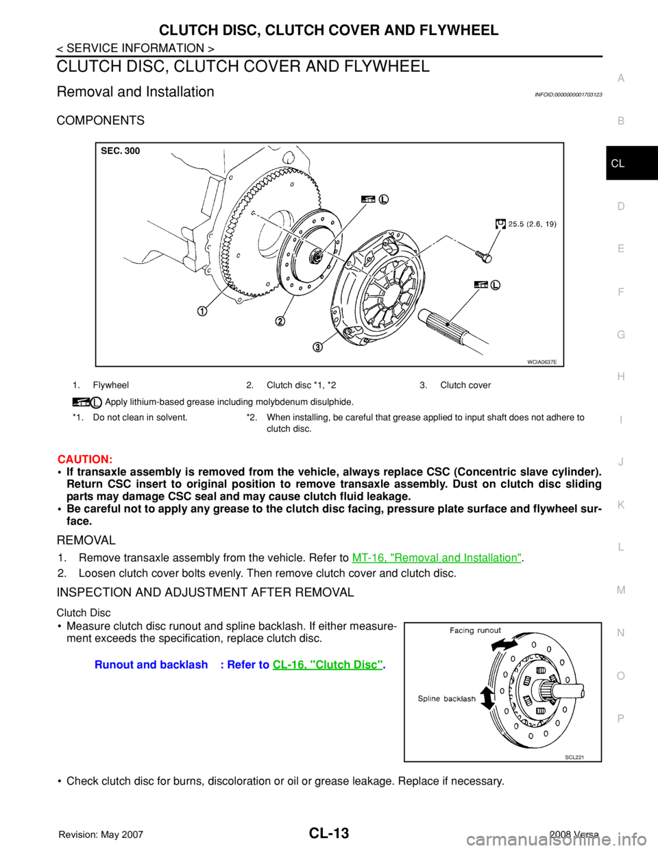
• Measure clutch disc runout and spline backlash. If either measure-
ment exceeds the specification, replace clutch disc.
• Check clutch disc for burns, discoloration or oil or grease leakage. Replace if necessary.
1. Flywheel 2. Clutch disc *1, *2 3. Clutch cover
Apply lithium-based grease including molybdenum disulphide.
*1. Do not clean in solvent. *2. When installing, be careful that grease applied to input shaft does not adhere to
clutch disc.
WCIA0637E
Runout and backlash : Refer to CL-16, "Clutch Disc".
SCL221
Page 816 of 2771

CLUTCH DISC, CLUTCH COVER AND FLYWHEEL
CL-15
< SERVICE INFORMATION >
D
E
F
G
H
I
J
K
L
MA
B
CL
N
O
P
5. Tighten clutch cover bolts evenly in two steps in the order
shown.
6. Install transaxle assembly. Refer to MT-16, "
Removal and Instal-
lation".
PCIB1772E
Page 843 of 2771
CVT-4
DTC P1740 LOCK-UP SELECT SOLENOID
VALVE CIRCUIT ..............................................
132
Description .............................................................132
CONSULT-III Reference Value in Data Monitor
Mode ......................................................................
132
On Board Diagnosis Logic .....................................132
Possible Cause ......................................................132
DTC Confirmation Procedure ................................132
Wiring Diagram - CVT - L/USSV ............................133
Diagnosis Procedure .............................................134
Component Inspection ...........................................135
DTC P1745 LINE PRESSURE CONTROL ......136
Description .............................................................136
On Board Diagnosis Logic .....................................136
Possible Cause ......................................................136
DTC Confirmation Procedure ................................136
Diagnosis Procedure .............................................136
DTC P1777 STEP MOTOR - CIRCUIT ............137
Description .............................................................137
CONSULT-III Reference Value in Data Monitor
Mode ......................................................................
137
On Board Diagnosis Logic .....................................137
Possible Cause ......................................................137
DTC Confirmation Procedure ................................137
Wiring Diagram - CVT - STM .................................138
Diagnosis Procedure .............................................139
Component Inspection ...........................................140
DTC P1778 STEP MOTOR - FUNCTION ........141
Description .............................................................141
CONSULT-III Reference Value in Data Monitor
Mode ......................................................................
141
On Board Diagnosis Logic .....................................141
Possible Cause ......................................................141
DTC Confirmation Procedure ................................141
Diagnosis Procedure .............................................142
OVERDRIVE CONTROL SWITCH ..................143
Description .............................................................143
CONSULT-III Reference Value in Data Monitor
Mode ......................................................................
143
Wiring Diagram - CVT - ODSW .............................144
Diagnosis Procedure .............................................144
Component Inspection ...........................................146
SHIFT POSITION INDICATOR CIRCUIT ........148
Description .............................................................148
CONSULT-III Reference Value in Data Monitor
Mode ......................................................................
148
Diagnosis Procedure .............................................148
TROUBLE DIAGNOSIS FOR SYMPTOMS .....149
Wiring Diagram - CVT - NONDTC .........................149
O/D OFF Indicator Lamp Does Not Come On ......151
Engine Cannot Be Started in "P" and "N" Position .153
In "P" Position, Vehicle Moves Forward or Back-
ward When Pushed ...............................................
153
In "N" Position, Vehicle Moves ..............................154
Large Shock "N" → "R" Position ...........................154
Vehicle Does Not Creep Backward in "R" Position .155
Vehicle Does Not Creep Forward in "D" or "L" Po-
sition ......................................................................
156
Vehicle Speed Does Not Change in "L" Position ..157
Vehicle Speed Does Not Change in overdrive-off
mode .....................................................................
158
Vehicle Speed Does Not Change in "D" Position .159
Vehicle Does Not Decelerate by Engine Brake ....159
TRANSMISSION CONTROL MODULE ...........161
Removal and Installation .......................................161
CVT SHIFT LOCK SYSTEM .............................162
Description ............................................................162
Shift Lock System Electrical Parts Location ..........162
Wiring Diagram - CVT - SHIFT .............................163
Diagnosis Procedure .............................................163
SHIFT CONTROL SYSTEM .............................167
Removal and Installation .......................................167
Control Device Disassembly and Assembly .........170
Selector Lever Knob Removal and Installation .....170
Adjustment of CVT Position ..................................171
Checking of CVT Position .....................................171
KEY INTERLOCK CABLE ...............................173
Removal and Installation .......................................173
AIR BREATHER HOSE ....................................176
Removal and Installation .......................................176
DIFFERENTIAL SIDE OIL SEAL .....................177
Removal and Installation .......................................177
TRANSAXLE ASSEMBLY ...............................178
Removal and Installation .......................................178
SERVICE DATA AND SPECIFICATIONS
(SDS) ................................................................
181
General Specification ............................................181
Vehicle Speed When Shifting Gears .....................181
Stall Speed ............................................................181
Line Pressure ........................................................181
Solenoid Valves ....................................................182
CVT Fluid Temperature Sensor ............................182
Primary Speed Sensor ..........................................182
Secondary Speed Sensor .....................................182
Removal and Installation .......................................182
Page 847 of 2771
CVT-8
< SERVICE INFORMATION >
PRECAUTIONS
• Be sure to turn the ignition switch OFF and disconnect the battery cable from the negative terminal
before any repair or inspection work. The open/short circuit of related switches, sensors, solenoid
valves, etc. will cause the MIL to light up.
• Be sure to connect and lock the connectors securely after work. A loose (unlocked) connector will
cause the MIL to light up due to an open circuit. (Be sure the connector is free from water, grease,
dirt, bent terminals, etc.)
• Be sure to route and secure the harnesses properly after work. Interference of the harness with a
bracket, etc. may cause the MIL to light up due to a short circuit.
• Be sure to connect rubber tubes properly after work. A misconnected or disconnected rubber tube
may cause the MIL to light up due to a malfunction of the EVAP system or fuel injection system, etc.
• Be sure to erase the unnecessary malfunction information (repairs completed) from the TCM and
ECM before returning the vehicle to the customer.
Service After Replacing TCM and Transaxle AssemblyINFOID:0000000001703427
SERVICE AFTER REPLACING TCM AND TRANSAXLE ASSEMBLY
Perform the applicable service in the following sheet when replacing TCM or transaxle assembly
CAUTION:
• Do not start the engine until the service is completed.
• “A/T C/U POWER SUPPLY [P1701]” may be indicated soon after replacing TCM or transaxle assem-
bly (after erasing the memory at the pattern B). Restart the self-diagnosis after erasing the self-diag-
nosis result. Check that no error is detected.
NOTE:
Old unit means that the unit has been already used for another vehicle.
PATTERN A
1. Shift the selector lever to “P” position after replacing TCM. Turn the ignition switch ON.
2. Check that the shift position indicator in the combination meter turns ON (It indicates approximately 1 or 2
seconds after turning the ignition switch ON.)
• Check the following items if the shift position indicator does not turn ON. Repair or replace the shift posi-
tion indicator if necessary.
- The harness between TCM and ROM ASSY in the transaxle assembly is open or short.
- Cable disconnected, loosen, or bent from the connector housing.
PATTERN B
1. Turn the ignition switch ON after replacing each part.
2. Start engine.
CAUTION:
Do not start the driving.
3. Touch CONSULT-III screen in the order of “START (NISSAN BASED VHCL)”, “TRANSMISSION”, “DATA
MONITOR”, and “MAIN SIGNALS”.
4. Warm up the transaxle assembly until “ATFTEMPCOUNT” indicates 47 [approximately 20°C (68°F)] or
more. Turn the ignition switch OFF.
5. Turn the ignition switch ON.
CAUTION:
Do not start engine.
6. Select “SELF-DIAG RESULTS”.
7. Shift the selector lever to “R” position.
8. Depress slightly the accelerator pedal (Pedal angle: 2/8) while depressing the brake pedal.
9. Perform “ERASE”.
TCM CVT assemblyService pattern
Replace the new unit. Do not replace the unit. "PATTERN A"
Do not replace the unit. Replace the new or old unit.
"PATTERN B"
Replace the old unit.Do not replace the unit.
Replace the new or old unit.
Replace the new unit. Replace the new or old unit. "PATTERN C"
Page 848 of 2771
PRECAUTIONS
CVT-9
< SERVICE INFORMATION >
D
E
F
G
H
I
J
K
L
MA
B
CVT
N
O
P
10. Shift the selector lever to “R” position after replacing TCM. Turn the ignition switch OFF.
11. Wait approximately 10 minutes after turning the ignition switch OFF.
12. Turn the ignition switch ON while shifting the selector lever to “R” position.
CAUTION:
Do not start engine.
13. Select “CALIBRATION DATA”.
14. Check that the value on “CALIBRATION DATA” is same as the data after erasing "Calibration Data".
• Restart the procedure from step 3 if the values are not same.
15. Shift the selector lever to “P” position.
16. Check that the shift position indicator in the combination meter turns ON (It indicates approximately 1 or 2
seconds after shifting the selector lever to “P” position.)
• Check the following items if the shift position indicator does not turn ON. Repair or replace the shift posi-
tion indicator if necessary.
- The harness between TCM and ROM ASSY in the transaxle assembly is open or short.
- Cable disconnected, loosen, or bent from the connector housing.
- Power supply and ground of TCM. Refer to CVT-121
.
PATTERN C
1. Replace the transaxle assembly first, and then replace TCM.
2. Perform the service of “PATTERN A”.
(Perform the service of “Pattern B” if TCM is replaced first.)
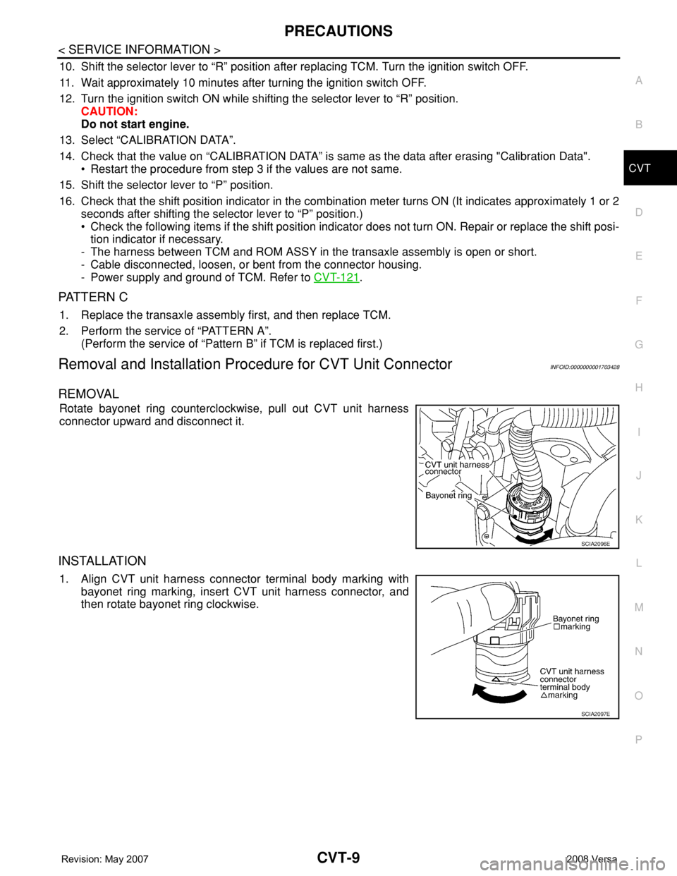
Removal and Installation Procedure for CVT Unit ConnectorINFOID:0000000001703428
REMOVAL
Rotate bayonet ring counterclockwise, pull out CVT unit harness
connector upward and disconnect it.
INSTALLATION
1. Align CVT unit harness connector terminal body marking with
bayonet ring marking, insert CVT unit harness connector, and
then rotate bayonet ring clockwise.
SCIA2096E
SCIA2097E
Page 849 of 2771
CVT-10
< SERVICE INFORMATION >
PRECAUTIONS
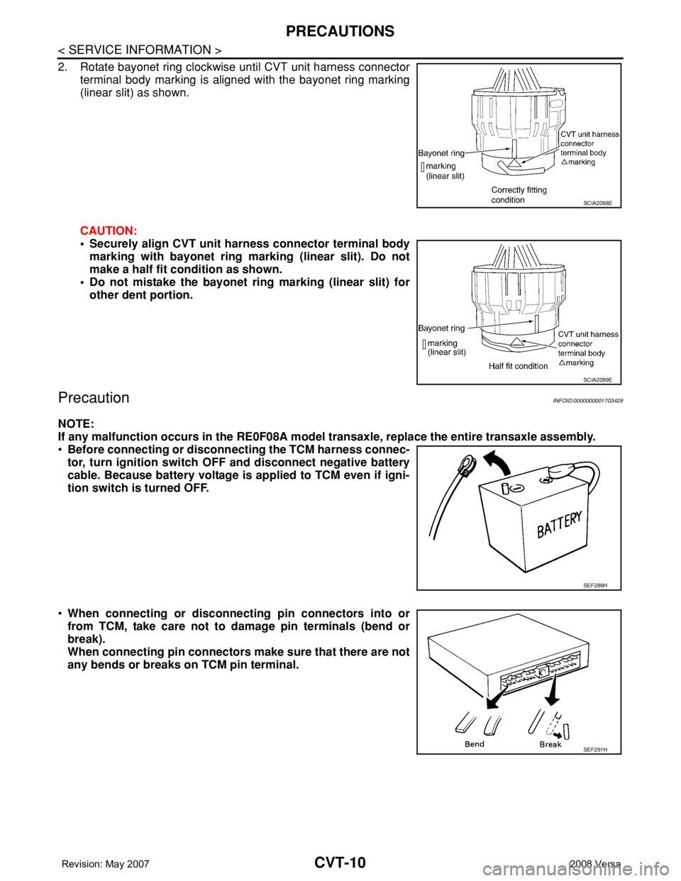
2. Rotate bayonet ring clockwise until CVT unit harness connector
terminal body marking is aligned with the bayonet ring marking
(linear slit) as shown.
CAUTION:
• Securely align CVT unit harness connector terminal body
marking with bayonet ring marking (linear slit). Do not
make a half fit condition as shown.
• Do not mistake the bayonet ring marking (linear slit) for
other dent portion.
PrecautionINFOID:0000000001703429
NOTE:
If any malfunction occurs in the RE0F08A model transaxle, replace the entire transaxle assembly.
•Before connecting or disconnecting the TCM harness connec-
tor, turn ignition switch OFF and disconnect negative battery
cable. Because battery voltage is applied to TCM even if igni-
tion switch is turned OFF.
•When connecting or disconnecting pin connectors into or
from TCM, take care not to damage pin terminals (bend or
break).
When connecting pin connectors make sure that there are not
any bends or breaks on TCM pin terminal.
SCIA2098E
SCIA2099E
SEF289H
SEF291H