bulb NISSAN TIIDA 2008 Service Owner's Manual
[x] Cancel search | Manufacturer: NISSAN, Model Year: 2008, Model line: TIIDA, Model: NISSAN TIIDA 2008Pages: 2771, PDF Size: 60.61 MB
Page 2175 of 2771

LT-38
< SERVICE INFORMATION >
HEADLAMP (FOR CANADA) - DAYTIME LIGHT SYSTEM -
DISASSEMBLY
1. Remove back cover.
2. Unlock retaining spring and remove bulb (High/Low).
3. Turn parking (clearance) lamp bulb socket counterclockwise and unlock it.
4. Remove parking (clearance) lamp bulb from its socket.
5. Turn front turn signal lamp bulb socket counterclockwise and unlock it.
6. Remove front turn signal lamp bulb from its socket.
7. Remove the bumper stay.
ASSEMBLY
Assembly is in the reverse order of disassembly.
CAUTION:
• After installing bulb, be sure to install plastic cap securely to insure water tight seal.
1. Retaining spring 2. Parking (clearance) lamp bulb 3. Parking (clearance) lamp bulb socket
4. Halogen bulb (High/Low) 5. Back cover 6. Front turn signal lamp bulb socket
7. Front turn signal lamp bulb 8. Headlamp housing assembly 9. Bumper stay
A. Screw
Page 2182 of 2771
FRONT FOG LAMP
LT-45
< SERVICE INFORMATION >
C
D
E
F
G
H
I
J
L
MA
B
LT
N
O
P
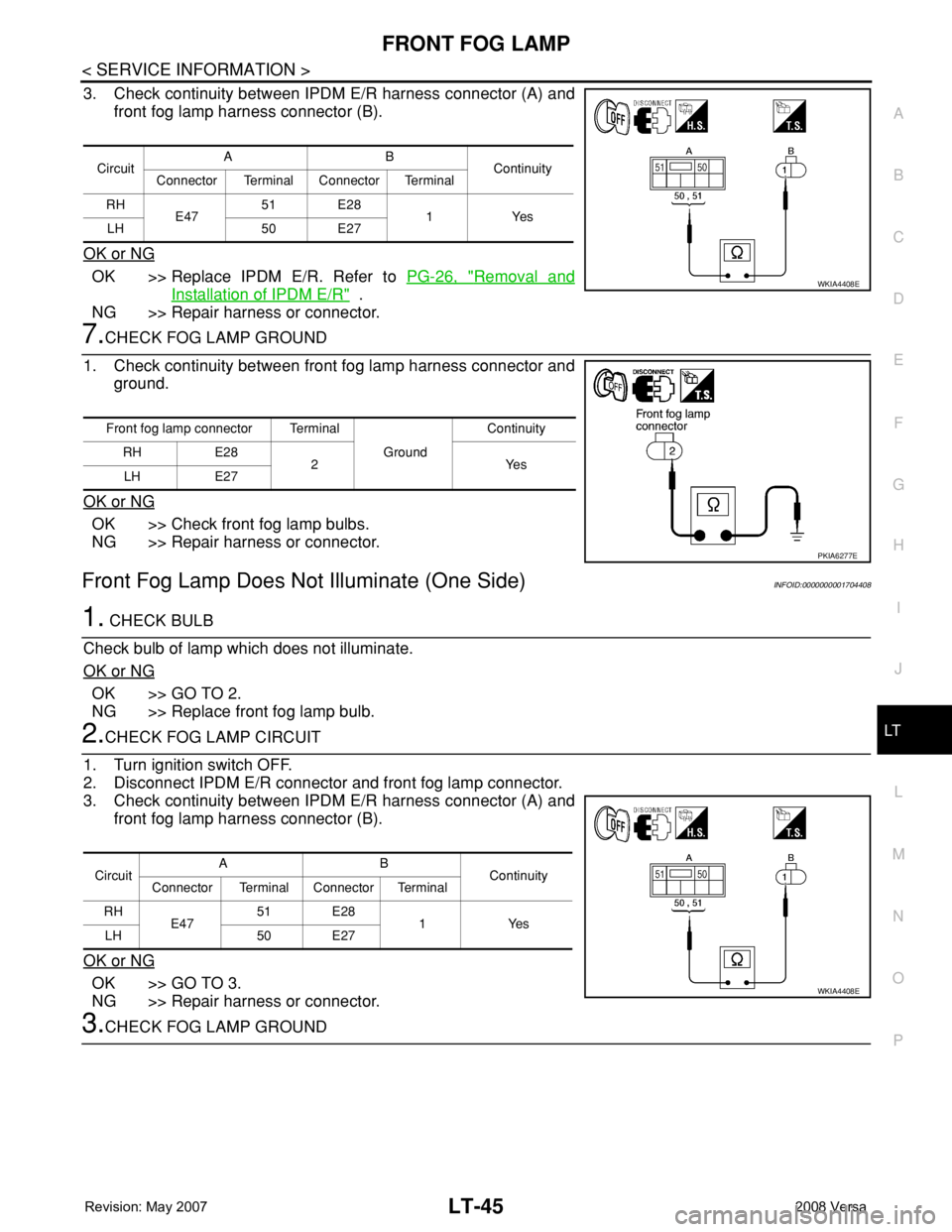
3. Check continuity between IPDM E/R harness connector (A) and
front fog lamp harness connector (B).
OK or NG
OK >> Replace IPDM E/R. Refer to PG-26, "Removal and
Installation of IPDM E/R" .
NG >> Repair harness or connector.
7.CHECK FOG LAMP GROUND
1. Check continuity between front fog lamp harness connector and
ground.
OK or NG
OK >> Check front fog lamp bulbs.
NG >> Repair harness or connector.
Front Fog Lamp Does Not Illuminate (One Side)INFOID:0000000001704408
1. CHECK BULB
Check bulb of lamp which does not illuminate.
OK or NG
OK >> GO TO 2.
NG >> Replace front fog lamp bulb.
2.CHECK FOG LAMP CIRCUIT
1. Turn ignition switch OFF.
2. Disconnect IPDM E/R connector and front fog lamp connector.
3. Check continuity between IPDM E/R harness connector (A) and
front fog lamp harness connector (B).
OK or NG
OK >> GO TO 3.
NG >> Repair harness or connector.
3.CHECK FOG LAMP GROUND
CircuitAB
Continuity
Connector Terminal Connector Terminal
RH
E4751 E28
1Yes
LH 50 E27
WKIA4408E
Front fog lamp connector Terminal
Ground Continuity
RH E28
2Yes
LH E27
PKIA6277E
CircuitAB
Continuity
Connector Terminal Connector Terminal
RH
E4751 E28
1Yes
LH 50 E27
WKIA4408E
Page 2183 of 2771
LT-46
< SERVICE INFORMATION >
FRONT FOG LAMP
1. Check continuity between front fog lamp harness connector and
ground.
OK or NG
OK >> Replace IPDM E/R. Refer to PG-26, "Removal and
Installation of IPDM E/R" .
NG >> Repair harness or connector.
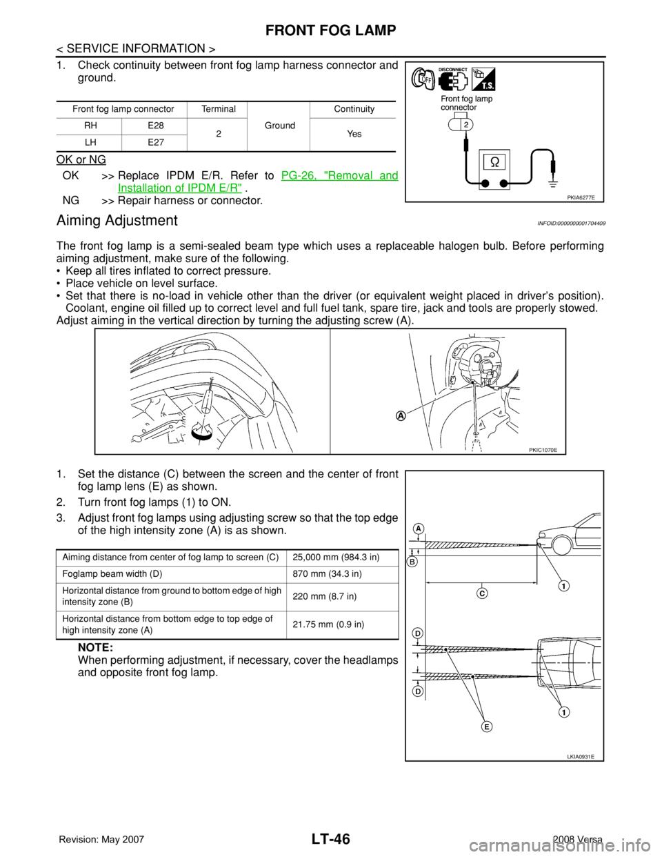
Aiming AdjustmentINFOID:0000000001704409
The front fog lamp is a semi-sealed beam type which uses a replaceable halogen bulb. Before performing
aiming adjustment, make sure of the following.
• Keep all tires inflated to correct pressure.
• Place vehicle on level surface.
• Set that there is no-load in vehicle other than the driver (or equivalent weight placed in driver’s position).
Coolant, engine oil filled up to correct level and full fuel tank, spare tire, jack and tools are properly stowed.
Adjust aiming in the vertical direction by turning the adjusting screw (A).
1. Set the distance (C) between the screen and the center of front
fog lamp lens (E) as shown.
2. Turn front fog lamps (1) to ON.
3. Adjust front fog lamps using adjusting screw so that the top edge
of the high intensity zone (A) is as shown.
NOTE:
When performing adjustment, if necessary, cover the headlamps
and opposite front fog lamp.
Front fog lamp connector Terminal
Ground Continuity
RH E28
2Yes
LH E27
PKIA6277E
PKIC1070E
Aiming distance from center of fog lamp to screen (C) 25,000 mm (984.3 in)
Foglamp beam width (D) 870 mm (34.3 in)
Horizontal distance from ground to bottom edge of high
intensity zone (B)220 mm (8.7 in)
Horizontal distance from bottom edge to top edge of
high intensity zone (A)21.75 mm (0.9 in)
LKIA0931E
Page 2184 of 2771
FRONT FOG LAMP
LT-47
< SERVICE INFORMATION >
C
D
E
F
G
H
I
J
L
MA
B
LT
N
O
P
Bulb ReplacementINFOID:0000000001704410
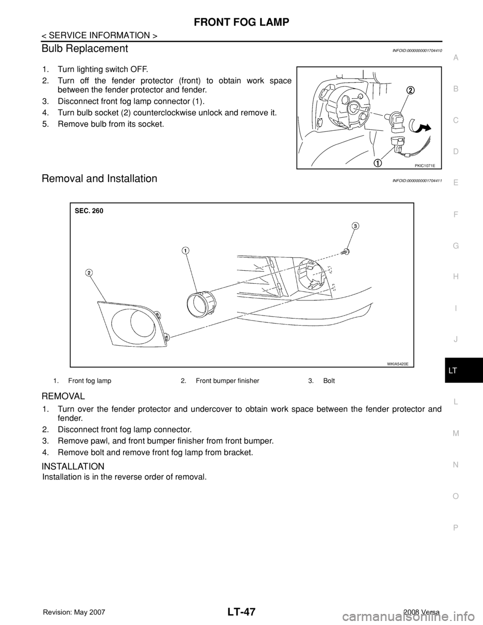
1. Turn lighting switch OFF.
2. Turn off the fender protector (front) to obtain work space
between the fender protector and fender.
3. Disconnect front fog lamp connector (1).
4. Turn bulb socket (2) counterclockwise unlock and remove it.
5. Remove bulb from its socket.
Removal and InstallationINFOID:0000000001704411
REMOVAL
1. Turn over the fender protector and undercover to obtain work space between the fender protector and
fender.
2. Disconnect front fog lamp connector.
3. Remove pawl, and front bumper finisher from front bumper.
4. Remove bolt and remove front fog lamp from bracket.
INSTALLATION
Installation is in the reverse order of removal.
PKIC1071E
1. Front fog lamp 2. Front bumper finisher 3. Bolt
WKIA5420E
Page 2193 of 2771
LT-56
< SERVICE INFORMATION >
TURN SIGNAL AND HAZARD WARNING LAMPS
3. Perform the preliminary check. Refer to LT-56, "Preliminary Check" .
4. Check symptom and repair or replace the cause of the malfunction.
5. Do turn signal and hazard warning lamps operate normally? If YES, GO TO 6. If NO, GO TO 4.
6. INSPECTION END
Preliminary CheckINFOID:0000000001704419
CHECK POWER SUPPLY AND GROUND CIRCUIT FOR BCM
Refer to BCS-15, "BCM Power Supply and Ground Circuit Inspection" .
CONSULT-III Function (BCM)INFOID:0000000001704420
Refer to LT- 11 , "CONSULT-III Function (BCM)" .
Turn Signals Do Not OperateINFOID:0000000001704421
1.CHECK COMBINATION SWITCH INPUT SIGNAL
With CONSULT-III
1. Select “BCM” on CONSULT-III. Select “FLASHER” on “SELECT TEST ITEM” screen.
2. Select “DATA MONITOR” on “SELECT DIAG MODE” screen. Make sure that “TURN SIGNAL R” and
“TURN SIGNAL L” turns ON-OFF linked with operation of lighting switch.
Without CONSULT-III
Refer to LT-63, "
Combination Switch Inspection" .
OK or NG
OK >> Replace the BCM. BCS-18, "Removal and Installation of BCM"
NG >> Check combination switch (lighting switch). Refer to LT-63, "Combination Switch Inspection" .
Front Turn Signal Lamp Does Not OperateINFOID:0000000001704422
1.CHECK BULB
Verify the bulb standard of each turn signal lamp is correct. Refer to LT-113, "
Exterior Lamp" .
OK or NG
OK >> GO TO 2.
NG >> Replace turn signal lamp bulb. Refer to LT-59, "
Bulb Replacement for Front Turn Signal Lamp" .
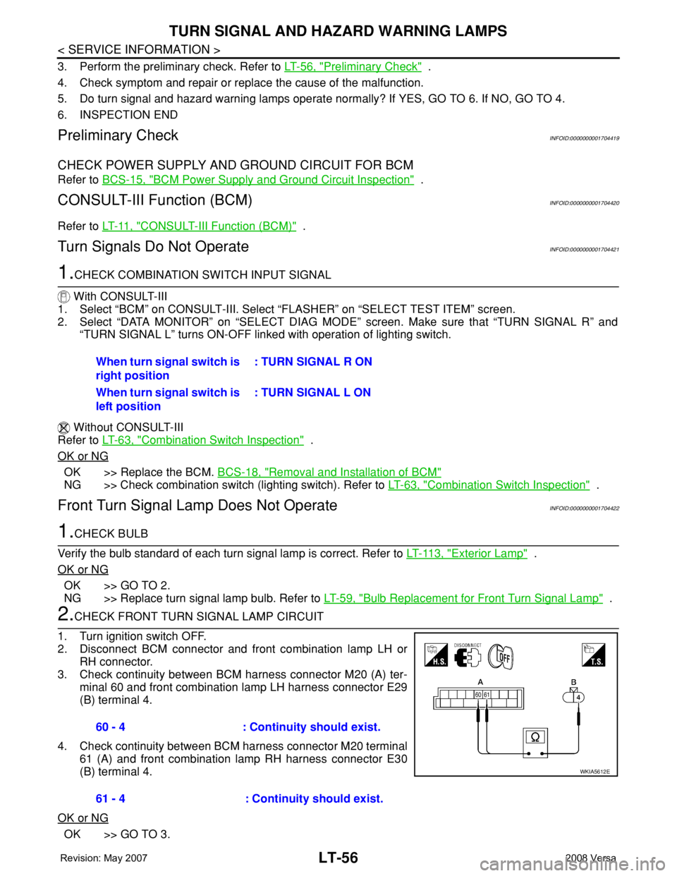
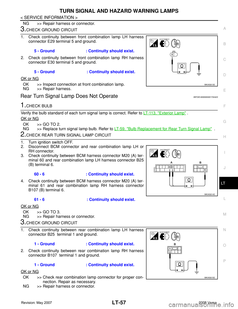
2.CHECK FRONT TURN SIGNAL LAMP CIRCUIT
1. Turn ignition switch OFF.
2. Disconnect BCM connector and front combination lamp LH or
RH connector.
3. Check continuity between BCM harness connector M20 (A) ter-
minal 60 and front combination lamp LH harness connector E29
(B) terminal 4.
4. Check continuity between BCM harness connector M20 terminal
61 (A) and front combination lamp RH harness connector E30
(B) terminal 4.
OK or NG
OK >> GO TO 3.When turn signal switch is
right position: TURN SIGNAL R ON
When turn signal switch is
left position: TURN SIGNAL L ON
60 - 4 : Continuity should exist.
61 - 4 : Continuity should exist.
WKIA5612E
Page 2194 of 2771
TURN SIGNAL AND HAZARD WARNING LAMPS
LT-57
< SERVICE INFORMATION >
C
D
E
F
G
H
I
J
L
MA
B
LT
N
O
P
NG >> Repair harness or connector.
3.CHECK GROUND CIRCUIT
1. Check continuity between front combination lamp LH harness
connector E29 terminal 5 and ground.
2. Check continuity between front combination lamp RH harness
connector E30 terminal 5 and ground.
OK or NG
OK >> Inspect connection at front combination lamp.
NG >> Repair harness.
Rear Turn Signal Lamp Does Not OperateINFOID:0000000001704423
1.CHECK BULB
Verify the bulb standard of each turn signal lamp is correct. Refer to LT-113, "
Exterior Lamp" .
OK or NG
OK >> GO TO 2.
NG >> Replace turn signal lamp bulb. Refer to LT-59, "
Bulb Replacement for Rear Turn Signal Lamp" .
2.CHECK REAR TURN SIGNAL LAMP CIRCUIT
1. Turn ignition switch OFF.
2. Disconnect BCM connector and rear combination lamp LH or
RH connector.
3. Check continuity between BCM harness connector M20 (A) ter-
minal 60 and rear combination lamp LH harness connector B25
(B) terminal 6.
4. Check continuity between BCM harness connector M20 (A) ter-
minal 61 and rear combination lamp RH harness connector
B107 (B) terminal 6.
OK or NG
OK >> GO TO 3.
NG >> Repair harness or connector.
3.CHECK GROUND CIRCUIT
1. Check continuity between rear combination lamp LH harness
connector B25 terminal 1 and ground.
2. Check continuity between rear combination lamp RH harness
connector B107 terminal 1 and ground.
OK or NG
OK >> Check rear combination lamp connector for proper con-
nection. Repair as necessary.
NG >> Repair harness or connector.5 - Ground : Continuity should exist.
5 - Ground : Continuity should exist.
WKIA5613E
60 - 6 : Continuity should exist.
61 - 6 : Continuity should exist.
WKIA5614E
1 - Ground : Continuity should exist.
1 - Ground : Continuity should exist.
WKIA5615E
Page 2196 of 2771
TURN SIGNAL AND HAZARD WARNING LAMPS
LT-59
< SERVICE INFORMATION >
C
D
E
F
G
H
I
J
L
MA
B
LT
N
O
P
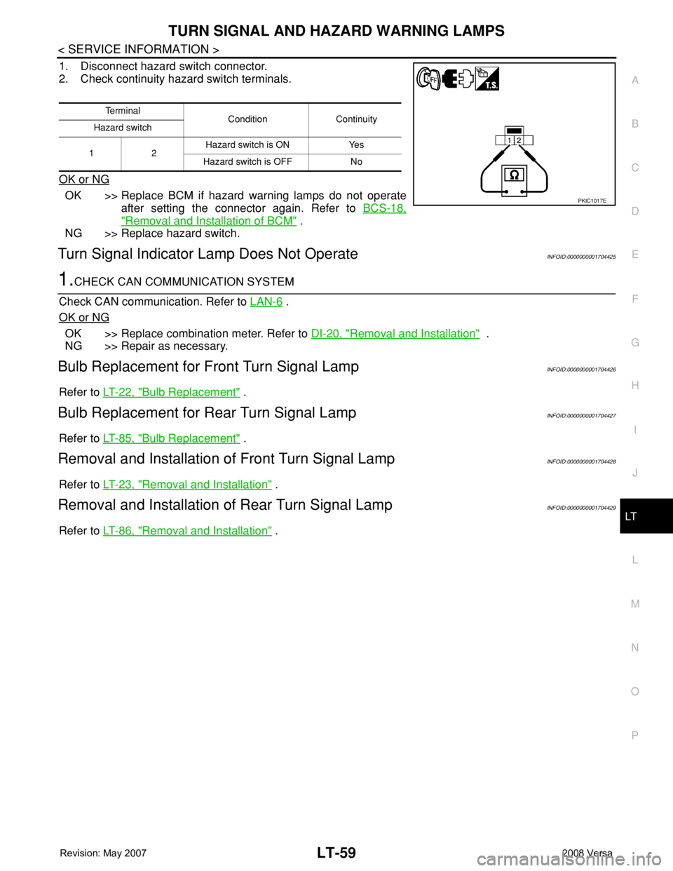
1. Disconnect hazard switch connector.
2. Check continuity hazard switch terminals.
OK or NG
OK >> Replace BCM if hazard warning lamps do not operate
after setting the connector again. Refer to BCS-18,
"Removal and Installation of BCM" .
NG >> Replace hazard switch.
Turn Signal Indicator Lamp Does Not OperateINFOID:0000000001704425
1.CHECK CAN COMMUNICATION SYSTEM
Check CAN communication. Refer to LAN-6
.
OK or NG
OK >> Replace combination meter. Refer to DI-20, "Removal and Installation" .
NG >> Repair as necessary.
Bulb Replacement for Front Turn Signal LampINFOID:0000000001704426
Refer to LT-22, "Bulb Replacement" .
Bulb Replacement for Rear Turn Signal LampINFOID:0000000001704427
Refer to LT-85, "Bulb Replacement" .
Removal and Installation of Front Turn Signal LampINFOID:0000000001704428
Refer to LT-23, "Removal and Installation" .
Removal and Installation of Rear Turn Signal LampINFOID:0000000001704429
Refer to LT-86, "Removal and Installation" .
Te r m i n a l
Condition Continuity
Hazard switch
12Hazard switch is ON Yes
Hazard switch is OFF No
PKIC1017E
Page 2204 of 2771
STOP LAMP
LT-67
< SERVICE INFORMATION >
C
D
E
F
G
H
I
J
L
MA
B
LT
N
O
P
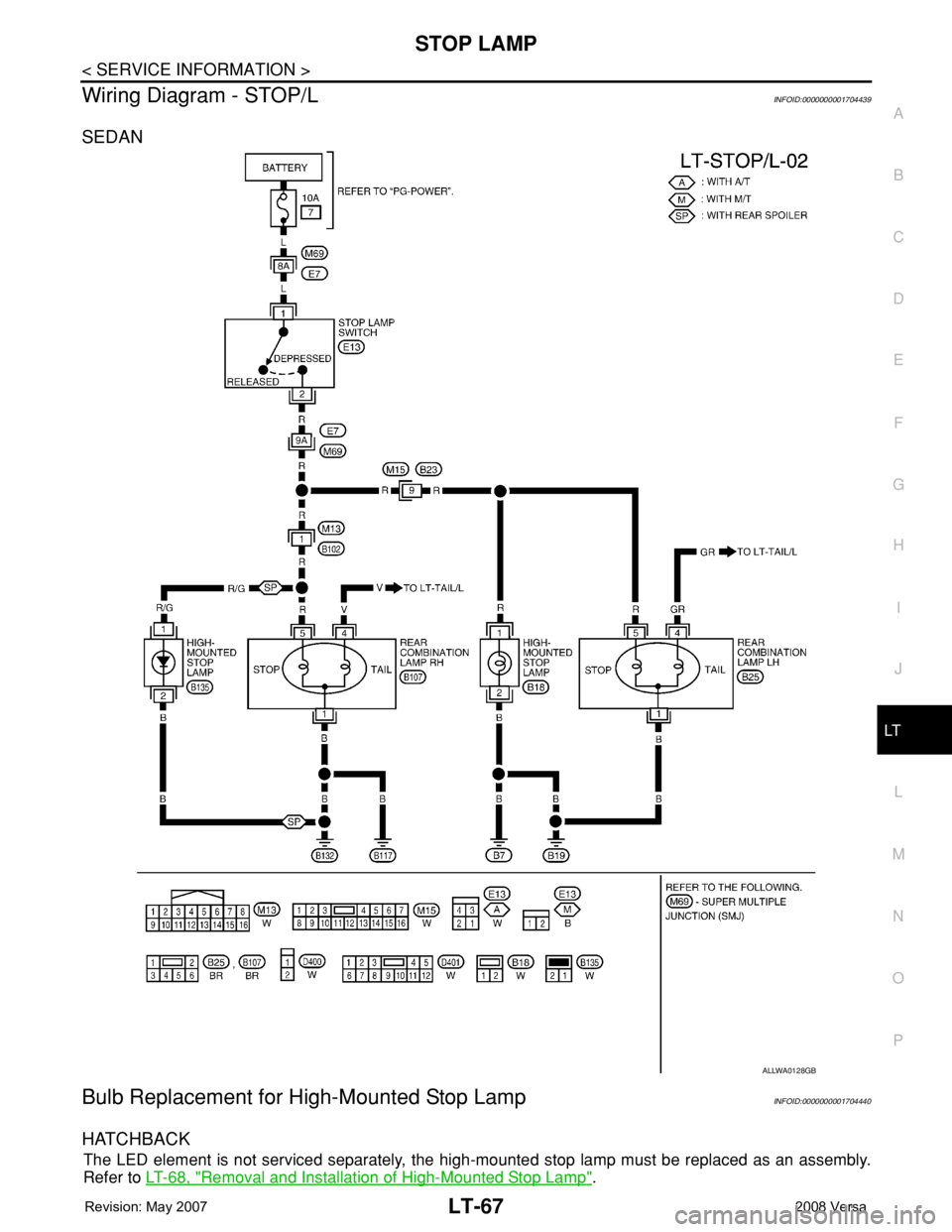
Wiring Diagram - STOP/LINFOID:0000000001704439
SEDAN
Bulb Replacement for High-Mounted Stop LampINFOID:0000000001704440
HATCHBACK
The LED element is not serviced separately, the high-mounted stop lamp must be replaced as an assembly.
Refer to LT-68, "
Removal and Installation of High-Mounted Stop Lamp".
ALLWA0128GB
Page 2205 of 2771
LT-68
< SERVICE INFORMATION >
STOP LAMP
SEDAN
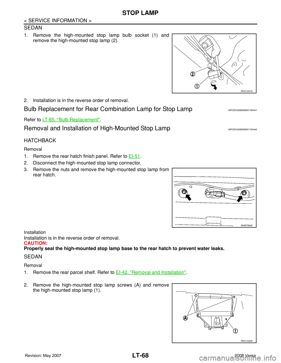
1. Remove the high-mounted stop lamp bulb socket (1) and
remove the high-mounted stop lamp (2).
2. Installation is in the reverse order of removal.
Bulb Replacement for Rear Combination Lamp for Stop LampINFOID:0000000001704441
Refer to LT-85, "Bulb Replacement".
Removal and Installation of High-Mounted Stop LampINFOID:0000000001704442
HATCHBACK
Removal
1. Remove the rear hatch finish panel. Refer to EI-51.
2. Disconnect the high-mounted stop lamp connector.
3. Remove the nuts and remove the high-mounted stop lamp from
rear hatch.
Installation
Installation is in the reverse order of removal.
CAUTION:
Properly seal the high-mounted stop lamp base to the rear hatch to prevent water leaks.
SEDAN
Removal
1. Remove the rear parcel shelf. Refer to EI-42, "Removal and Installation".
2. Remove the high-mounted stop lamp screws (A) and remove
the high-mounted stop lamp (1).
PKIC1021E
SKIB7594E
PKIC1022E
Page 2207 of 2771
LT-70
< SERVICE INFORMATION >
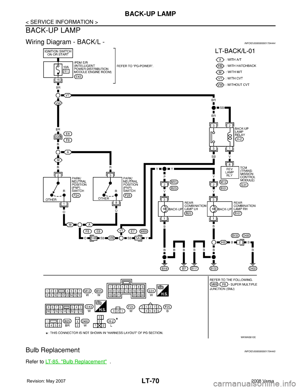
BACK-UP LAMP
BACK-UP LAMP
Wiring Diagram - BACK/L -INFOID:0000000001704444
Bulb ReplacementINFOID:0000000001704445
Refer to LT-85, "Bulb Replacement" .
WKWA5810E