fail-safe NISSAN TIIDA 2008 Service Owner's Guide
[x] Cancel search | Manufacturer: NISSAN, Model Year: 2008, Model line: TIIDA, Model: NISSAN TIIDA 2008Pages: 2771, PDF Size: 60.61 MB
Page 1162 of 2771
EC-88
< SERVICE INFORMATION >
TROUBLE DIAGNOSIS
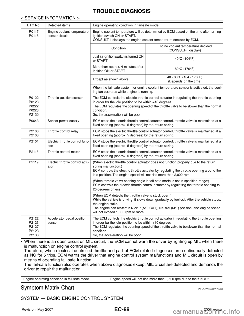
• When there is an open circuit on MIL circuit, the ECM cannot warn the driver by lighting up MIL when there
is malfunction on engine control system.
Therefore, when electrical controlled throttle and part of ECM related diagnoses are continuously detected
as NG for 5 trips, ECM warns the driver that engine control system malfunctions and MIL circuit is open by
means of operating fail-safe function.
The fail-safe function also operates when above diagnoses except MIL circuit are detected and demands the
driver to repair the malfunction.
Symptom Matrix ChartINFOID:0000000001702589
SYSTEM — BASIC ENGINE CONTROL SYSTEM
P0117
P0118Engine coolant temperature
sensor circuitEngine coolant temperature will be determined by ECM based on the time after turning
ignition switch ON or START.
CONSULT-II displays the engine coolant temperature decided by ECM.
ConditionEngine coolant temperature decided
(CONSULT-II display)
Just as ignition switch is turned ON
or START40°C (104°F)
More than approx. 4 minutes after
ignition ON or START80°C (176°F)
Except as shown above40 - 80°C (104 - 176°F)
(Depends on the time)
When the fail-safe system for engine coolant temperature sensor is activated, the cool-
ing fan operates while engine is running.
P0122
P0123
P0222
P0223
P2135Throttle position sensor The ECM controls the electric throttle control actuator in regulating the throttle opening
in order for the idle position to be within +10 degrees.
The ECM regulates the opening speed of the throttle valve to be slower than the normal
condition.
So, the acceleration will be poor.
P0643 Sensor power supply ECM stops the electric throttle control actuator control, throttle valve is maintained at a
fixed opening (approx. 5 degrees) by the return spring.
P2100
P2103Throttle control relay ECM stops the electric throttle control actuator control, throttle valve is maintained at a
fixed opening (approx. 5 degrees) by the return spring.
P2101 Electric throttle control func-
tionECM stops the electric throttle control actuator control, throttle valve is maintained at a
fixed opening (approx. 5 degrees) by the return spring.
P2118 Throttle control motor ECM stops the electric throttle control actuator control, throttle valve is maintained at a
fixed opening (approx. 5 degrees) by the return spring.
P2119 Electric throttle control actu-
ator(When electric throttle control actuator does not function properly due to the return
spring malfunction:)
ECM controls the electric throttle actuator by regulating the throttle opening around the
idle position. The engine speed will not rise more than 2,000 rpm.
(When throttle valve opening angle in fail-safe mode is not in specified range:)
ECM controls the electric throttle control actuator by regulating the throttle opening to
20 degrees or less.
(When ECM detects the throttle valve is stuck open:)
While the vehicle is driving, it slows down gradually by fuel cut. After the vehicle stops,
the engine stalls.
The engine can restart in N or P (A/T, CVT), Neutral (M/T) position, and engine speed
will not exceed 1,000 rpm or more.
P2122
P2123
P2127
P2128
P2138Accelerator pedal position
sensorThe ECM controls the electric throttle control actuator in regulating the throttle opening
in order for the idle position to be within +10 degrees.
The ECM regulates the opening speed of the throttle valve to be slower than the normal
condition.
So, the acceleration will be poor. DTC No. Detected items Engine operating condition in fail-safe mode
Engine operating condition in fail-safe mode Engine speed will not rise more than 2,500 rpm due to the fuel cut
Page 1187 of 2771

TROUBLE DIAGNOSIS
EC-113
< SERVICE INFORMATION >
C
D
E
F
G
H
I
J
K
L
MA
EC
N
P O
*: The items are the same as those of 1st trip freeze frame data.
DATA MONITOR MODE
Monitored Item
×: Applicable
INT/A TEMP SE
[°C] or [°F]• The intake air temperature at the moment a malfunction is detected is displayed.
FUEL SYS-B2
• Always a certain value is displayed.
• These items can not efficiently for C11 models. L-FUEL TRM-B2 [%]
S-FUEL TRM-B2 [%]
INT MANI PRES [kPa]
FTFMCH1Freeze frame data
item*Description
Monitored item [Unit]ECM IN-
PUT SIG-
NALSMAIN
SIG-
NALSDescription Remarks
ENG SPEED [rpm]×ו Indicates the engine speed computed from the
signals of the crankshaft position sensor (POS)
and camshaft position sensor (PHASE).• Accuracy becomes poor if engine
speed drops below the idle rpm.
• If the signal is interrupted while
the engine is running, an abnor-
mal value may be indicated.
MAS A/F SE-B1 [V]×ו The signal voltage of the mass air flow sensor
is displayed.• When the engine is stopped, a
certain value is indicated.
B/FUEL SCHDL
[msec]ו “Base fuel schedule” indicates the fuel injection
pulse width programmed into ECM, prior to any
learned on board correction.
A/F ALPHA-B1 [%]ו The mean value of the air-fuel ratio feedback
correction factor per cycle is indicated.• When the engine is stopped, a
certain value is indicated.
• This data also includes the data
for the air/fuel ratio learning con-
trol.
COOLAN TEMP/S
[°C] or [°F]×ו The engine coolant temperature (determined
by the signal voltage of the engine coolant tem-
perature sensor) is displayed.• When the engine coolant temper-
ature sensor is open or short-cir-
cuited, ECM enters fail-safe
mode. The engine coolant tem-
perature determined by the ECM
is displayed.
A/F SEN1 (B1) [V]×ו The A/F signal computed from the input signal
of the A/F sensor 1 is displayed.
HO2S2 (B1) [V]ו The signal voltage of the heated oxygen sensor
2 is displayed.
HO2S2 MNTR (B1)
[RICH/LEAN]ו Display of heated oxygen sensor 2 signal:
RICH: means the amount of oxygen after three
way catalyst is relatively small.
LEAN: means the amount of oxygen after three
way catalyst is relatively large.• When the engine is stopped, a
certain value is indicated.
VHCL SPEED SE
[km/h] or [mph]×ו The vehicle speed computed from the vehicle
speed signal is displayed.
BATTERY VOLT [V]×ו The power supply voltage of ECM is displayed.
ACCEL SEN 1 [V]××
• The accelerator pedal position sensor signal
voltage is displayed.• ACCEL SEN 2 signal is converted
by ECM internally. Thus, it differs
from ECM terminal voltage signal. ACCEL SEN 2 [V]×
THRTL SEN 1 [V]××
• The throttle position sensor signal voltage is
displayed.• THRTL SEN 2 signal is converted
by ECM internally. Thus, it differs
from ECM terminal voltage signal. THRTL SEN 2 [V]×
Page 1222 of 2771
EC-148
< SERVICE INFORMATION >
DTC P0011 IVT CONTROL
On Board Diagnosis Logic
INFOID:0000000001702619
FAIL-SAFE MODE
ECM enters in fail-safe mode when the malfunction is detected.
DTC Confirmation ProcedureINFOID:0000000001702620
CAUTION:
Always drive at a safe speed.
NOTE:
•If DTC P0011 is displayed with DTC P0075, first perform trouble diagnosis for DTC P0075.
See EC-162
.
• If DTC Confirmation Procedure has been previously conducted, always turn ignition switch OFF and wait at
least 10 seconds before conducting the next test.
TESTING CONDITION:
Before performing the following procedure, confirm that battery voltage is between 10V and 16V at
idle.
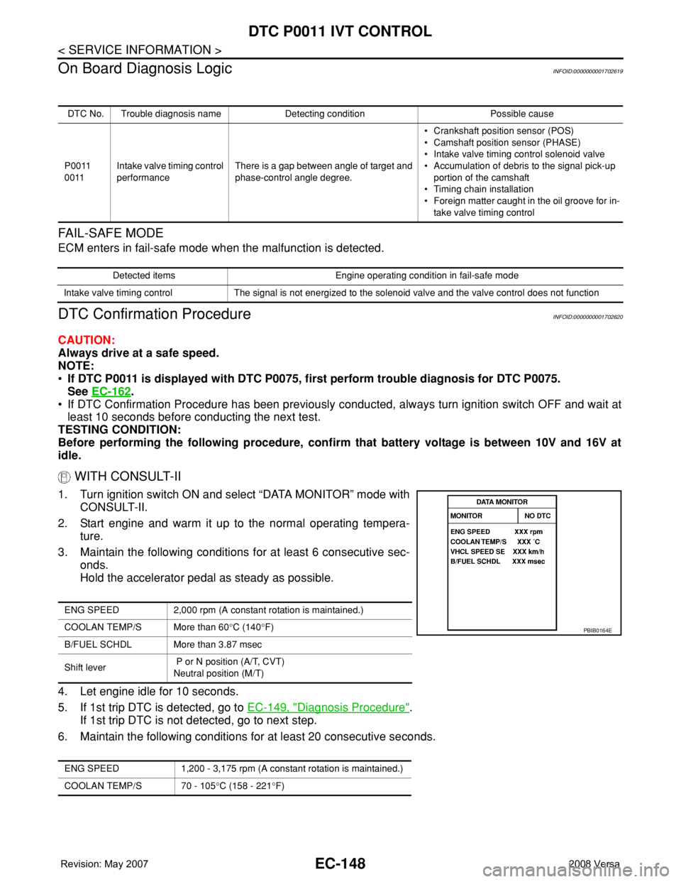
WITH CONSULT-II
1. Turn ignition switch ON and select “DATA MONITOR” mode with
CONSULT-II.
2. Start engine and warm it up to the normal operating tempera-
ture.
3. Maintain the following conditions for at least 6 consecutive sec-
onds.
Hold the accelerator pedal as steady as possible.
4. Let engine idle for 10 seconds.
5. If 1st trip DTC is detected, go to EC-149, "
Diagnosis Procedure".
If 1st trip DTC is not detected, go to next step.
6. Maintain the following conditions for at least 20 consecutive seconds.
DTC No. Trouble diagnosis name Detecting condition Possible cause
P0011
0011Intake valve timing control
performanceThere is a gap between angle of target and
phase-control angle degree.• Crankshaft position sensor (POS)
• Camshaft position sensor (PHASE)
• Intake valve timing control solenoid valve
• Accumulation of debris to the signal pick-up
portion of the camshaft
• Timing chain installation
• Foreign matter caught in the oil groove for in-
take valve timing control
Detected items Engine operating condition in fail-safe mode
Intake valve timing control The signal is not energized to the solenoid valve and the valve control does not function
ENG SPEED 2,000 rpm (A constant rotation is maintained.)
COOLAN TEMP/S More than 60°C (140°F)
B/FUEL SCHDL More than 3.87 msec
Shift lever P or N position (A/T, CVT)
Neutral position (M/T)
ENG SPEED 1,200 - 3,175 rpm (A constant rotation is maintained.)
COOLAN TEMP/S 70 - 105°C (158 - 221°F)
PBIB0164E
Page 1249 of 2771
DTC P0102, P0103 MAF SENSOR
EC-175
< SERVICE INFORMATION >
C
D
E
F
G
H
I
J
K
L
MA
EC
N
P O
DTC P0102, P0103 MAF SENSOR
Component DescriptionINFOID:0000000001702657
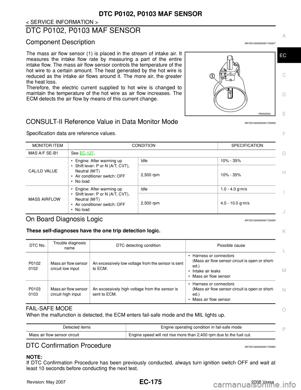
The mass air flow sensor (1) is placed in the stream of intake air. It
measures the intake flow rate by measuring a part of the entire
intake flow. The mass air flow sensor controls the temperature of the
hot wire to a certain amount. The heat generated by the hot wire is
reduced as the intake air flows around it. The more air, the greater
the heat loss.
Therefore, the electric current supplied to hot wire is changed to
maintain the temperature of the hot wire as air flow increases. The
ECM detects the air flow by means of this current change.
CONSULT-II Reference Value in Data Monitor ModeINFOID:0000000001702658
Specification data are reference values.
On Board Diagnosis LogicINFOID:0000000001702659
These self-diagnoses have the one trip detection logic.
FAIL-SAFE MODE
When the malfunction is detected, the ECM enters fail-safe mode and the MIL lights up.
DTC Confirmation ProcedureINFOID:0000000001702660
NOTE:
If DTC Confirmation Procedure has been previously conducted, always turn ignition switch OFF and wait at
least 10 seconds before conducting the next test.
PBIA9559J
MONITOR ITEM CONDITION SPECIFICATION
MAS A/F SE-B1 See EC-127
.
CAL/LD VALUE• Engine: After warming up
• Shift lever: P or N (A/T, CVT),
Neutral (M/T)
• Air conditioner switch: OFF
•No loadIdle 10% - 35%
2,500 rpm 10% - 35%
MASS AIRFLOW• Engine: After warming up
• Shift lever: P or N (A/T, CVT),
Neutral (M/T)
• Air conditioner switch: OFF
•No loadIdle 1.0 - 4.0 g·m/s
2,500 rpm 4.0 - 10.0 g·m/s
DTC No.Trouble diagnosis
nameDTC detecting condition Possible cause
P0102
0102Mass air flow sensor
circuit low inputAn excessively low voltage from the sensor is sent
to ECM.• Harness or connectors
(Mass air flow sensor circuit is open or short-
ed.)
• Intake air leaks
• Mass air flow sensor
P0103
0103Mass air flow sensor
circuit high inputAn excessively high voltage from the sensor is
sent to ECM.• Harness or connectors
(Mass air flow sensor circuit is open or short-
ed.)
• Mass air flow sensor
Detected items Engine operating condition in fail-safe mode
Mass air flow sensor circuit Engine speed will not rise more than 2,400 rpm due to the fuel cut.
Page 1261 of 2771

DTC P0117, P0118 ECT SENSOR
EC-187
< SERVICE INFORMATION >
C
D
E
F
G
H
I
J
K
L
MA
EC
N
P O
DTC P0117, P0118 ECT SENSOR
Component DescriptionINFOID:0000000001702672
The engine coolant temperature sensor is used to detect the engine
coolant temperature. The sensor modifies a voltage signal from the
ECM. The modified signal returns to the ECM as the engine coolant
temperature input. The sensor uses a thermistor which is sensitive to
the change in temperature. The electrical resistance of the ther-
mistor decreases as temperature increases.
*: This data is reference value and is measured between ECM terminal 38 (Engine
coolant temperature sensor) and ground.
CAUTION:
Do not use ECM ground terminals when measuring input/output voltage. Doing so may result in dam-
age to the ECM's transistor. Use a ground other than ECM terminals, such as the ground.
On Board Diagnosis LogicINFOID:0000000001702673
These self-diagnoses have the one trip detection logic.
FAIL-SAFE MODE
When the malfunction is detected, the ECM enters fail-safe mode and the MIL lights up.
SEF594K
Engine coolant temperature
°C (°F)Voltage* V Resistance kΩ
–10 (14) 4.4 7.0 - 11.4
20 (68) 3.5 2.1 - 2.9
50 (122) 2.2 0.68 - 1.00
90 (194) 0.9 0.236 - 0.260
SEF012P
DTC No.Trouble Diagnosis
NameDTC Detecting Condition Possible Cause
P0117
0117Engine coolant tem-
perature sensor cir-
cuit low inputAn excessively low voltage from the sensor is
sent to ECM.• Harness or connectors
(Engine coolant temperature sensor circuit is
open or shorted.)
• Engine coolant temperature sensor P0118
0118Engine coolant tem-
perature sensor cir-
cuit high inputAn excessively high voltage from the sensor is
sent to ECM.
Page 1262 of 2771

EC-188
< SERVICE INFORMATION >
DTC P0117, P0118 ECT SENSOR
DTC Confirmation Procedure
INFOID:0000000001702674
NOTE:
If DTC Confirmation Procedure has been previously conducted, always turn ignition switch OFF and wait at
least 10 seconds before conducting the next test.
WITH CONSULT-II
1. Turn ignition switch ON.
2. Select “DATA MONITOR” mode with CONSULT-II.
3. Wait at least 5 seconds.
4. If DTC is detected, go to EC-189, "
Diagnosis Procedure".
WITH GST
Follow the procedure “WITH CONSULT-II” above.
Detected items Engine operating condition in fail-safe mode
Engine coolant temper-
ature sensor circuitEngine coolant temperature will be determined by ECM based on the time after turning ignition switch ON
or START.
CONSULT-II displays the engine coolant temperature decided by ECM.
ConditionEngine coolant temperature decided
(CONSULT-II display)
Just as ignition switch is turned ON or START 40°C (104°F)
More than approx. 4 minutes after ignition ON or START 80°C (176°F)
Except as shown above40 - 80°C (104 - 176°F)
(Depends on the time)
When the fail-safe system for engine coolant temperature sensor is activated, the cooling fan operates while
engine is running.
SEF058Y
Page 1266 of 2771
EC-192
< SERVICE INFORMATION >
DTC P0122, P0123 TP SENSOR
DTC P0122, P0123 TP SENSOR
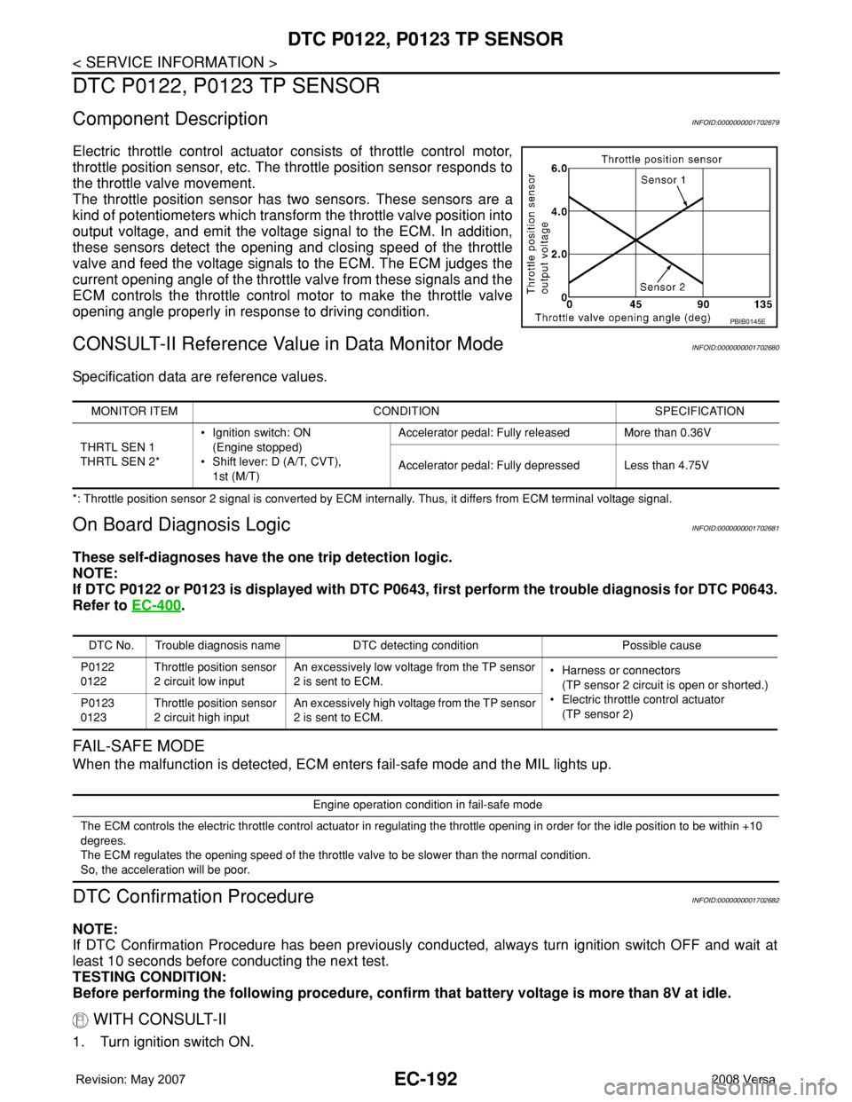
Component DescriptionINFOID:0000000001702679
Electric throttle control actuator consists of throttle control motor,
throttle position sensor, etc. The throttle position sensor responds to
the throttle valve movement.
The throttle position sensor has two sensors. These sensors are a
kind of potentiometers which transform the throttle valve position into
output voltage, and emit the voltage signal to the ECM. In addition,
these sensors detect the opening and closing speed of the throttle
valve and feed the voltage signals to the ECM. The ECM judges the
current opening angle of the throttle valve from these signals and the
ECM controls the throttle control motor to make the throttle valve
opening angle properly in response to driving condition.
CONSULT-II Reference Value in Data Monitor ModeINFOID:0000000001702680
Specification data are reference values.
*: Throttle position sensor 2 signal is converted by ECM internally. Thus, it differs from ECM terminal voltage signal.
On Board Diagnosis LogicINFOID:0000000001702681
These self-diagnoses have the one trip detection logic.
NOTE:
If DTC P0122 or P0123 is displayed with DTC P0643, first perform the trouble diagnosis for DTC P0643.
Refer to EC-400
.
FAIL-SAFE MODE
When the malfunction is detected, ECM enters fail-safe mode and the MIL lights up.
DTC Confirmation ProcedureINFOID:0000000001702682
NOTE:
If DTC Confirmation Procedure has been previously conducted, always turn ignition switch OFF and wait at
least 10 seconds before conducting the next test.
TESTING CONDITION:
Before performing the following procedure, confirm that battery voltage is more than 8V at idle.
WITH CONSULT-II
1. Turn ignition switch ON.
PBIB0145E
MONITOR ITEM CONDITION SPECIFICATION
THRTL SEN 1
THRTL SEN 2*• Ignition switch: ON
(Engine stopped)
• Shift lever: D (A/T, CVT),
1st (M/T)Accelerator pedal: Fully released More than 0.36V
Accelerator pedal: Fully depressed Less than 4.75V
DTC No. Trouble diagnosis name DTC detecting condition Possible cause
P0122
0122Throttle position sensor
2 circuit low inputAn excessively low voltage from the TP sensor
2 is sent to ECM.• Harness or connectors
(TP sensor 2 circuit is open or shorted.)
• Electric throttle control actuator
(TP sensor 2) P0123
0123Throttle position sensor
2 circuit high inputAn excessively high voltage from the TP sensor
2 is sent to ECM.
Engine operation condition in fail-safe mode
The ECM controls the electric throttle control actuator in regulating the throttle opening in order for the idle position to be within +10
degrees.
The ECM regulates the opening speed of the throttle valve to be slower than the normal condition.
So, the acceleration will be poor.
Page 1352 of 2771
EC-278
< SERVICE INFORMATION >
DTC P0222, P0223 TP SENSOR
DTC P0222, P0223 TP SENSOR
Component DescriptionINFOID:0000000001702782
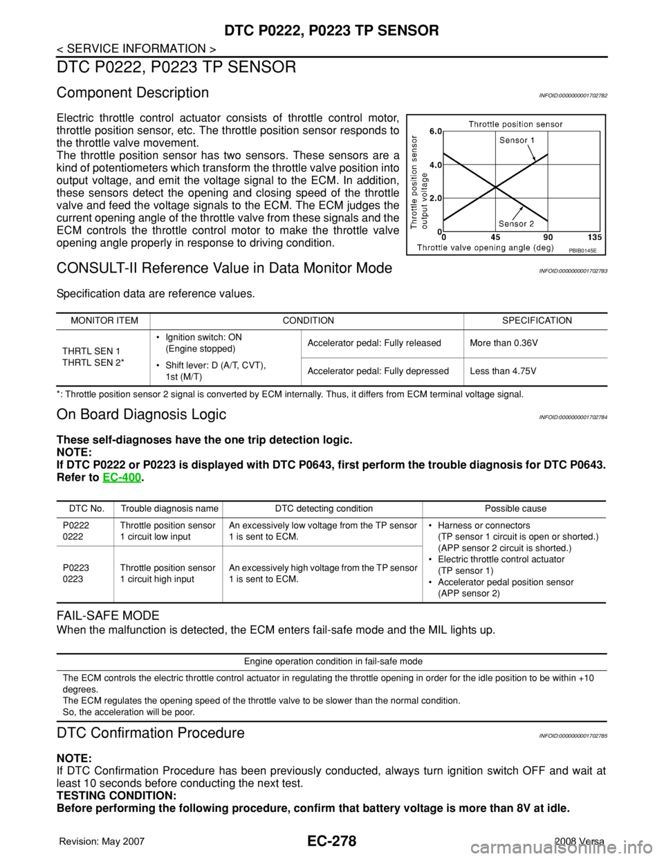
Electric throttle control actuator consists of throttle control motor,
throttle position sensor, etc. The throttle position sensor responds to
the throttle valve movement.
The throttle position sensor has two sensors. These sensors are a
kind of potentiometers which transform the throttle valve position into
output voltage, and emit the voltage signal to the ECM. In addition,
these sensors detect the opening and closing speed of the throttle
valve and feed the voltage signals to the ECM. The ECM judges the
current opening angle of the throttle valve from these signals and the
ECM controls the throttle control motor to make the throttle valve
opening angle properly in response to driving condition.
CONSULT-II Reference Value in Data Monitor ModeINFOID:0000000001702783
Specification data are reference values.
*: Throttle position sensor 2 signal is converted by ECM internally. Thus, it differs from ECM terminal voltage signal.
On Board Diagnosis LogicINFOID:0000000001702784
These self-diagnoses have the one trip detection logic.
NOTE:
If DTC P0222 or P0223 is displayed with DTC P0643, first perform the trouble diagnosis for DTC P0643.
Refer to EC-400
.
FAIL-SAFE MODE
When the malfunction is detected, the ECM enters fail-safe mode and the MIL lights up.
DTC Confirmation ProcedureINFOID:0000000001702785
NOTE:
If DTC Confirmation Procedure has been previously conducted, always turn ignition switch OFF and wait at
least 10 seconds before conducting the next test.
TESTING CONDITION:
Before performing the following procedure, confirm that battery voltage is more than 8V at idle.
PBIB0145E
MONITOR ITEM CONDITION SPECIFICATION
THRTL SEN 1
THRTL SEN 2*• Ignition switch: ON
(Engine stopped)Accelerator pedal: Fully released More than 0.36V
• Shift lever: D (A/T, CVT),
1st (M/T)Accelerator pedal: Fully depressed Less than 4.75V
DTC No. Trouble diagnosis name DTC detecting condition Possible cause
P0222
0222Throttle position sensor
1 circuit low inputAn excessively low voltage from the TP sensor
1 is sent to ECM.• Harness or connectors
(TP sensor 1 circuit is open or shorted.)
(APP sensor 2 circuit is shorted.)
• Electric throttle control actuator
(TP sensor 1)
• Accelerator pedal position sensor
(APP sensor 2) P0223
0223Throttle position sensor
1 circuit high inputAn excessively high voltage from the TP sensor
1 is sent to ECM.
Engine operation condition in fail-safe mode
The ECM controls the electric throttle control actuator in regulating the throttle opening in order for the idle position to be within +10
degrees.
The ECM regulates the opening speed of the throttle valve to be slower than the normal condition.
So, the acceleration will be poor.
Page 1465 of 2771
DTC P0500 VSS
EC-391
< SERVICE INFORMATION >
C
D
E
F
G
H
I
J
K
L
MA
EC
N
P O
DTC P0500 VSS
DescriptionINFOID:0000000001702900
NOTE:
•If DTC P0500 is displayed with DTC U1000 or U1001, first perform the trouble diagnosis for DTC
U1000, U1001. Refer to EC-143
.
•If DTC P0500 is displayed with DTC U1010, first perform the trouble diagnosis for DTC U1010. Refer
to EC-145
.
The vehicle speed signal is sent to the combination meter from “ABS actuator and electric unit (control unit)”
through CAN communication line. The combination meter then sends a signal to the ECM through CAN com-
munication line.
On Board Diagnosis LogicINFOID:0000000001702901
FAIL-SAFE MODE
When the malfunction is detected, ECM enters fail-safe mode.
DTC Confirmation ProcedureINFOID:0000000001702902
CAUTION:
Always drive vehicle at a safe speed.
NOTE:
If DTC Confirmation Procedure has been previously conducted, always turn ignition switch OFF and wait at
least 10 seconds before conducting the next test.
TESTING CONDITION:
Steps 1 and 2 may be conducted with the drive wheels lifted in the shop or by driving the vehicle. If a
road test is expected to be easier, it is unnecessary to lift the vehicle.
WITH CONSULT-II
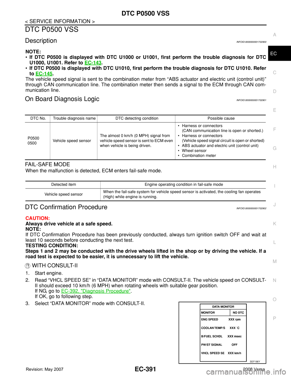
1. Start engine.
2. Read “VHCL SPEED SE” in “DATA MONITOR” mode with CONSULT-II. The vehicle speed on CONSULT-
II should exceed 10 km/h (6 MPH) when rotating wheels with suitable gear position.
If NG, go to EC-392, "
Diagnosis Procedure".
If OK, go to following step.
3. Select “DATA MONITOR” mode with CONSULT-II.
DTC No. Trouble diagnosis name DTC detecting condition Possible cause
P0500
0500Vehicle speed sensorThe almost 0 km/h (0 MPH) signal from
vehicle speed sensor is sent to ECM even
when vehicle is being driven.• Harness or connectors
(CAN communication line is open or shorted.)
• Harness or connectors
(Vehicle speed signal circuit is open or shorted)
• ABS actuator and electric unit (control unit)
• Wheel sensor
• Combination meter
Detected item Engine operating condition in fail-safe mode
Vehicle speed sensorWhen the fail-safe system for vehicle speed sensor is activated, the cooling fan operates
(High) while engine is running.
SEF196Y
Page 1471 of 2771
DTC P0605 ECM
EC-397
< SERVICE INFORMATION >
C
D
E
F
G
H
I
J
K
L
MA
EC
N
P O
DTC P0605 ECM
Component DescriptionINFOID:0000000001702913
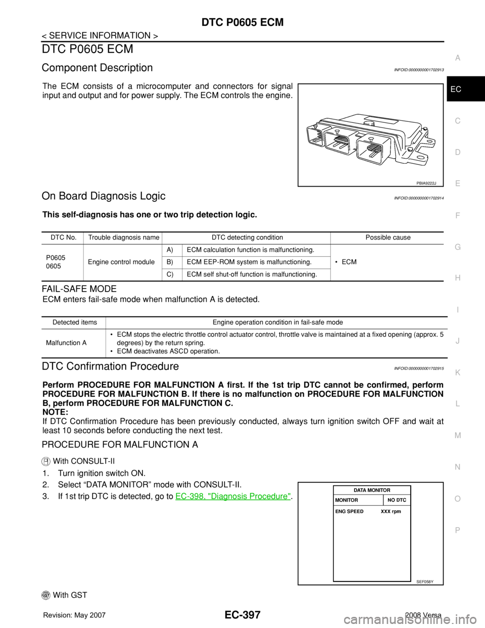
The ECM consists of a microcomputer and connectors for signal
input and output and for power supply. The ECM controls the engine.
On Board Diagnosis LogicINFOID:0000000001702914
This self-diagnosis has one or two trip detection logic.
FAIL-SAFE MODE
ECM enters fail-safe mode when malfunction A is detected.
DTC Confirmation ProcedureINFOID:0000000001702915
Perform PROCEDURE FOR MALFUNCTION A first. If the 1st trip DTC cannot be confirmed, perform
PROCEDURE FOR MALFUNCTION B. If there is no malfunction on PROCEDURE FOR MALFUNCTION
B, perform PROCEDURE FOR MALFUNCTION C.
NOTE:
If DTC Confirmation Procedure has been previously conducted, always turn ignition switch OFF and wait at
least 10 seconds before conducting the next test.
PROCEDURE FOR MALFUNCTION A
With CONSULT-II
1. Turn ignition switch ON.
2. Select “DATA MONITOR” mode with CONSULT-II.
3. If 1st trip DTC is detected, go to EC-398, "
Diagnosis Procedure".
With GST
PBIA9222J
DTC No. Trouble diagnosis name DTC detecting condition Possible cause
P0605
0605Engine control moduleA) ECM calculation function is malfunctioning.
•ECM B) ECM EEP-ROM system is malfunctioning.
C) ECM self shut-off function is malfunctioning.
Detected items Engine operation condition in fail-safe mode
Malfunction A• ECM stops the electric throttle control actuator control, throttle valve is maintained at a fixed opening (approx. 5
degrees) by the return spring.
• ECM deactivates ASCD operation.
SEF058Y