fail-safe NISSAN TIIDA 2008 Service User Guide
[x] Cancel search | Manufacturer: NISSAN, Model Year: 2008, Model line: TIIDA, Model: NISSAN TIIDA 2008Pages: 2771, PDF Size: 60.61 MB
Page 766 of 2771
BRC-1
BRAKES
C
D
E
G
H
I
J
K
L
M
SECTION BRC
A
B
BRC
N
O
P
CONTENTS
BRAKE CONTROL SYSTEM
ABS
SERVICE INFORMATION ............................
2
PRECAUTIONS ...................................................2
Precaution for Supplemental Restraint System
(SRS) "AIR BAG" and "SEAT BELT PRE-TEN-
SIONER" ...................................................................
2
Precaution for Brake System ....................................2
Precaution for Brake Control .....................................2
Precaution for CAN System ......................................3
PREPARATION ...................................................4
Special Service Tool .................................................4
Commercial Service Tool ..........................................4
SYSTEM DESCRIPTION .....................................5
System Component ...................................................5
ABS Function ............................................................5
EBD Function ............................................................5
Fail-Safe Function .....................................................5
Hydraulic Circuit Diagram .........................................6
CAN COMMUNICATION .....................................7
System Description ...................................................7
TROUBLE DIAGNOSIS ......................................8
How to Perform Trouble Diagnosis for Quick and
Accurate Repair ........................................................
8
Component Parts and Harness Connector Loca-
tion ..........................................................................
11
Schematic ...............................................................12
Wiring Diagram - ABS - ...........................................13
Basic Inspection ......................................................16
Warning Lamp and Indicator Timing ........................17
Control Unit Input/Output Signal Standard ..............17
CONSULT-III Function (ABS) ..................................18
TROUBLE DIAGNOSIS FOR SELF-DIAG-
NOSTIC ITEMS .................................................
24
Wheel Sensor System .............................................24
ABS Control Unit Inspection ....................................25
Solenoid Valve System Inspection ..........................25
Actuator Motor, Motor Relay, and Circuit Inspec-
tion ...........................................................................
26
ABS Control Unit Power and Ground Systems In-
spection ...................................................................
27
CAN Communication System Inspection .................28
TROUBLE DIAGNOSES FOR SYMPTOMS .....29
ABS Works Frequently ............................................29
Unexpected Pedal Action ........................................29
Long Stopping Distance ..........................................30
ABS Does Not Work ................................................30
Pedal Vibration or ABS Operation Noise .................30
WHEEL SENSORS ...........................................32
Removal and Installation .........................................32
SENSOR ROTOR ..............................................34
Removal and Installation .........................................34
ACTUATOR AND ELECTRIC UNIT (ASSEM-
BLY) ..................................................................
35
Removal and Installation .........................................35
Page 770 of 2771

SYSTEM DESCRIPTION
BRC-5
< SERVICE INFORMATION >[ABS]
C
D
E
G
H
I
J
K
L
MA
B
BRC
N
O
P
SYSTEM DESCRIPTION
System ComponentINFOID:0000000001703825
ABS FunctionINFOID:0000000001703826
• The Anti-Lock Brake System detects wheel revolution while braking and improves handling stability during
sudden braking by electrically preventing wheel lockup. Maneuverability is also improved for avoiding obsta-
cles during emergency braking.
• If the electrical system malfunctions, the Fail-Safe function is activated, the ABS becomes inoperative and
the ABS warning lamp turns on.
• The electrical system can be diagnosed using CONSULT-III.
• During ABS operation, the brake pedal may vibrate lightly and a mechanical noise may be heard. This is
normal.
• Just after starting the vehicle, the brake pedal may vibrate or motor operating noises may be heard from the
engine compartment. This is normal due to the self check operation.
• Stopping distance may be longer than that of vehicles without ABS when vehicle drives on rough, gravel, or
snow-covered (fresh, deep snow) roads.
EBD FunctionINFOID:0000000001703827
• Electronic Brake Distribution is a function that detects subtle slippages between the front and rear wheels
during braking, and it improves handling stability by electronically controlling the brake fluid pressure which
results in reduced rear wheel slippage.
• If the electrical system malfunctions, the Fail-Safe function is activated, the EBD and ABS become inopera-
tive, and the ABS warning lamp and brake warning lamp are turned on.
• The electrical system can be diagnosed using CONSULT-III.
• During EBD operation, the brake pedal may vibrate lightly and a mechanical noise may be heard. This is
normal.
• Just after starting the vehicle, the brake pedal may vibrate or motor operating noises may be heard from the
engine compartment. This is normal due to the self check operation.
Fail-Safe FunctionINFOID:0000000001703828
CAUTION:
If the Fail-Safe function is activated, perform the Self Diagnosis for ABS system.
ABS/EBD SYSTEM
In case of an electrical malfunction with the ABS, the ABS warning lamp will turn on. In case of an electrical
malfunction with the EBD system, the brake warning lamp and the ABS warning lamp will turn on.
The system will revert to one of the following conditions of the Fail-Safe function.
1. For ABS malfunction, only the EBD is operative and the condition of the vehicle is the same condition of
vehicles without ABS system.
WFIA0118E
Page 783 of 2771

BRC-18
< SERVICE INFORMATION >[ABS]
TROUBLE DIAGNOSIS
Note 1: Confirm tire pressure is normal.
Note 2: ON/OFF timing of ABS warning lamp
ON: For approximately 2 seconds after ignition switch is turned ON, or when a malfunction is detected.
OFF: Approximately 2 seconds after ignition switch is turned ON (when system is in normal operation).
CONSULT-III Function (ABS)INFOID:0000000001703838
CONSULT-III can display each diagnostic item using the diagnostic test modes shown following.
Monitor item Display contentData monitor
Note: Error inspection
checklist
ConditionReference value in
normal operation
FR RH SENSOR
FR LH SENSOR
RR RH SENSOR
RR LH SENSORWheel speedVehicle stopped 0 [km/h (MPH)]
BRC-24, "
Wheel Sensor
System"Vehicle running (Note 1)Almost in accor-
dance with speed-
ometer display
(within ±10%)
BATTERY VOLTBattery voltage sup-
plied to ABS actuator
and electric unit (con-
trol unit)Ignition switch ON 10 to 16VBRC-27, "
ABS Control
Unit Power and Ground
Systems Inspection"
STOP LAMP SWStop lamp switch oper-
ationBrake pedal depressed ON
—
Brake pedal not depressed OFF
ABS WARN LAMPABS warning lamp ON
condition (Note 2)ABS warning lamp ON ON
BRC-16, "
Basic Inspec-
tion"ABS warning lamp OFF OFF
MOTOR RELAYOperation status of mo-
tor and motor relayIgnition switch ON or running
(ABS not activated)OFF
BRC-26, "
Actuator Motor,
Motor Relay, and Circuit
Inspection"Ignition switch ON or engine
running (ABS activated)ON
ACTUATOR RLYActuator relay opera-
tion statusVehicle stopped (Ignition
switch ON)OFF
BRC-26, "
Actuator Motor,
Motor Relay, and Circuit
Inspection"Vehicle stopped (Engine run-
ning)ON
FR LH IN SOL
FR LH OUT SOL
FR RH IN SOL
FR RH OUT SOL
RR RH IN SOL
RR RH OUT SOL
RR LH IN SOL
RR LH OUT SOLSolenoid valve opera-
tionActuator (solenoid) is active
(“ACTIVE TEST” with CON-
SULT-III) or actuator relay is in-
active (in fail-safe mode).ON
BRC-25, "
Solenoid Valve
System Inspection"When actuator (solenoid) is not
active and actuator relay is ac-
tive (ignition switch ON).OFF
ABS SIGNAL
EBD SIGNALSignal statusABS active
EBD activeON
ABS system
EBD system
ABS not active
EBD not activeOFF
ABS FAIL SIG
EBD FAIL SIGFail signal statusABS fail
EBD failON
ABS system
EBD system
ABS normal
EBD normalOFF
ABS diagnostic mode Description
SELF-DIAG RESULTS Displays ABS actuator and electric unit (control unit) self-diagnosis results.
DATA MONITOR Displays ABS actuator and electric unit (control unit) input/output data in real time.
CAN DIAG SUPPORT MNTR The result of transmit/receive diagnosis of CAN communication can be read.
ACTIVE TEST Operation of electrical loads can be checked by sending drive signal to them.
Page 840 of 2771
CVT-1
TRANSMISSION/TRANSAXLE
D
E
F
G
H
I
J
K
L
M
SECTION CVT
A
B
CVT
N
O
P
CONTENTS
CVT
SERVICE INFORMATION ............................5
INDEX FOR DTC .................................................5
Alphabetical Index .....................................................5
DTC No. Index ..........................................................5
PRECAUTIONS ...................................................7
Precaution for Supplemental Restraint System
(SRS) "AIR BAG" and "SEAT BELT PRE-TEN-
SIONER" ...................................................................
7
Precaution Necessary for Steering Wheel Rota-
tion After Battery Disconnect .....................................
7
Precaution for On Board Diagnosis (OBD) System
of CVT and Engine ....................................................
7
Service After Replacing TCM and Transaxle As-
sembly .......................................................................
8
Removal and Installation Procedure for CVT Unit
Connector ..................................................................
9
Precaution ...............................................................10
Service Notice or Precaution ...................................11
PREPARATION ..................................................12
Special Service Tool ...............................................12
Commercial Service Tool ........................................12
CVT FLUID .........................................................13
Checking CVT Fluid ................................................13
Changing CVT Fluid ................................................14
CVT Fluid Cooler Cleaning .....................................14
CVT SYSTEM .....................................................18
Cross-Sectional View - RE0F08A ...........................18
Control System ........................................................19
Hydraulic Control System ........................................20
TCM Function ..........................................................20
CAN Communication ...............................................21
Input/Output Signal of TCM .....................................22
Line Pressure and Secondary Pressure Control .....22
Shift Control ............................................................23
Lock-up and Select Control .....................................24
Control Valve ...........................................................25
ON BOARD DIAGNOSTIC (OBD) SYSTEM ....26
Introduction ..............................................................26
OBD-II Function for CVT System ............................26
One or Two Trip Detection Logic of OBD-II .............26
OBD-II Diagnostic Trouble Code (DTC) ..................26
Malfunction Indicator Lamp (MIL) ............................27
TROUBLE DIAGNOSIS ....................................29
DTC Inspection Priority Chart ..................................29
Fail-Safe ..................................................................29
How to Perform Trouble Diagnosis for Quick and
Accurate Repair .......................................................
30
CVT Electrical Parts Location ..................................35
Circuit Diagram ........................................................36
Inspections before Trouble Diagnosis .....................36
Road Test ................................................................40
Check before Engine Is Started ...............................41
Check at Idle ............................................................41
Cruise Test ..............................................................43
Vehicle Speed When Shifting Gears .......................45
TCM Terminal and Reference Value .......................45
CONSULT-III Function (TRANSMISSION) ..............47
Diagnosis Procedure without CONSULT-III ............55
DTC U1000 CAN COMMUNICATION LINE .....56
Description ...............................................................56
On Board Diagnosis Logic .......................................56
Possible Cause ........................................................56
DTC Confirmation Procedure ..................................56
Wiring Diagram - CVT - CAN ...................................57
Diagnosis Procedure ...............................................58
DTC U1010 TRANSMISSION CONTROL
MODULE (CAN) ................................................
59
Description ...............................................................59
On Board Diagnosis Logic .......................................59
Possible Cause ........................................................59
DTC Confirmation Procedure ..................................59
Diagnosis Procedure ...............................................59
DTC P0615 START SIGNAL CIRCUIT .............60
Page 859 of 2771
CVT-20
< SERVICE INFORMATION >
CVT SYSTEM
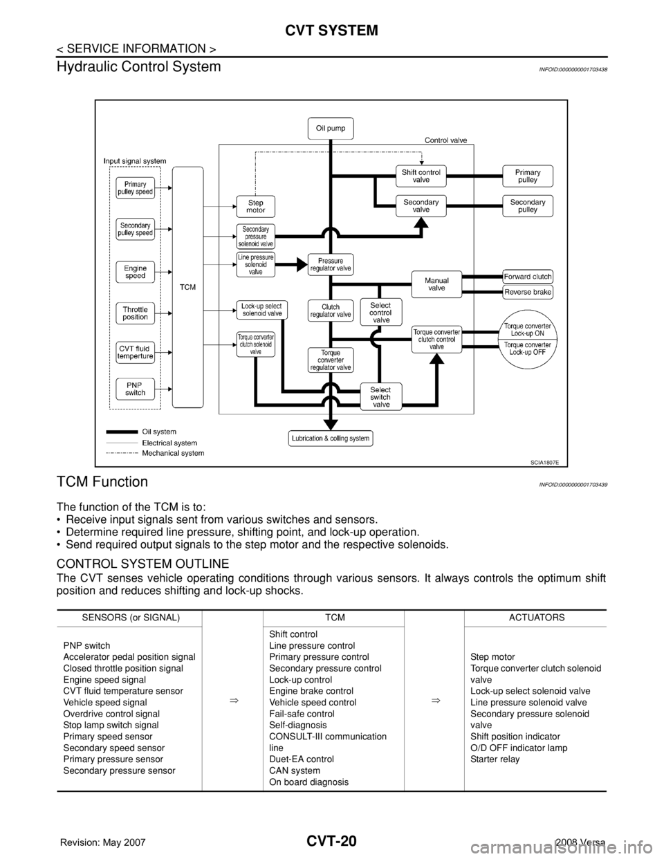
Hydraulic Control System
INFOID:0000000001703438
TCM FunctionINFOID:0000000001703439
The function of the TCM is to:
• Receive input signals sent from various switches and sensors.
• Determine required line pressure, shifting point, and lock-up operation.
• Send required output signals to the step motor and the respective solenoids.
CONTROL SYSTEM OUTLINE
The CVT senses vehicle operating conditions through various sensors. It always controls the optimum shift
position and reduces shifting and lock-up shocks.
SCIA1807E
SENSORS (or SIGNAL)
⇒TCM
⇒ACTUATORS
PNP switch
Accelerator pedal position signal
Closed throttle position signal
Engine speed signal
CVT fluid temperature sensor
Vehicle speed signal
Overdrive control signal
Stop lamp switch signal
Primary speed sensor
Secondary speed sensor
Primary pressure sensor
Secondary pressure sensorShift control
Line pressure control
Primary pressure control
Secondary pressure control
Lock-up control
Engine brake control
Vehicle speed control
Fail-safe control
Self-diagnosis
CONSULT-III communication
line
Duet-EA control
CAN system
On board diagnosisSte p m ot or
Torque converter clutch solenoid
valve
Lock-up select solenoid valve
Line pressure solenoid valve
Secondary pressure solenoid
valve
Shift position indicator
O/D OFF indicator lamp
Starter relay
Page 861 of 2771
CVT-22
< SERVICE INFORMATION >
CVT SYSTEM
Input/Output Signal of TCM
INFOID:0000000001703441
*1: Input by CAN communications.
*2: Output by CAN communications.
*3: If these input and output signals are different, the TCM triggers the fail-safe function.
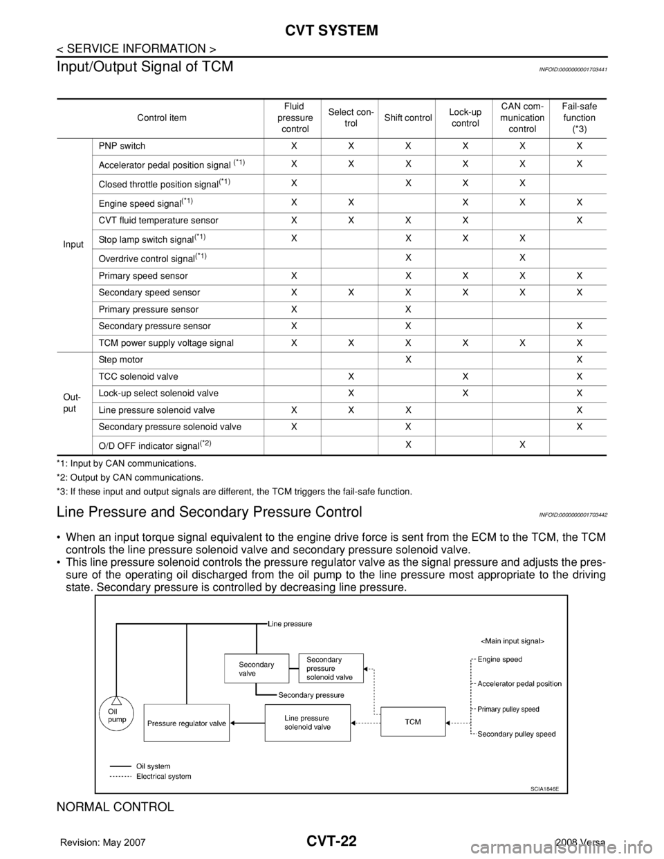
Line Pressure and Secondary Pressure ControlINFOID:0000000001703442
• When an input torque signal equivalent to the engine drive force is sent from the ECM to the TCM, the TCM
controls the line pressure solenoid valve and secondary pressure solenoid valve.
• This line pressure solenoid controls the pressure regulator valve as the signal pressure and adjusts the pres-
sure of the operating oil discharged from the oil pump to the line pressure most appropriate to the driving
state. Secondary pressure is controlled by decreasing line pressure.
NORMAL CONTROL
Control itemFluid
pressure
controlSelect con-
trolShift controlLock-up
controlCAN com-
munication
controlFail-safe
function
(*3)
InputPNP switch XXXXXX
Accelerator pedal position signal
(*1)XXXXXX
Closed throttle position signal
(*1)X XXX
Engine speed signal
(*1)XX XXX
CVT fluid temperature sensor X X X X X
Stop lamp switch signal
(*1)X XXX
Overdrive control signal
(*1)XX
Primary speed sensor X X X X X
Secondary speed sensor X X X X X X
Primary pressure sensor X X
Secondary pressure sensor X X X
TCM power supply voltage signal X X X X X X
Out-
putStep motor X X
TCC solenoid valve X X X
Lock-up select solenoid valve X X X
Line pressure solenoid valve X X X X
Secondary pressure solenoid valve X X X
O/D OFF indicator signal
(*2)XX
SCIA1846E
Page 868 of 2771
TROUBLE DIAGNOSIS
CVT-29
< SERVICE INFORMATION >
D
E
F
G
H
I
J
K
L
MA
B
CVT
N
O
P
TROUBLE DIAGNOSIS
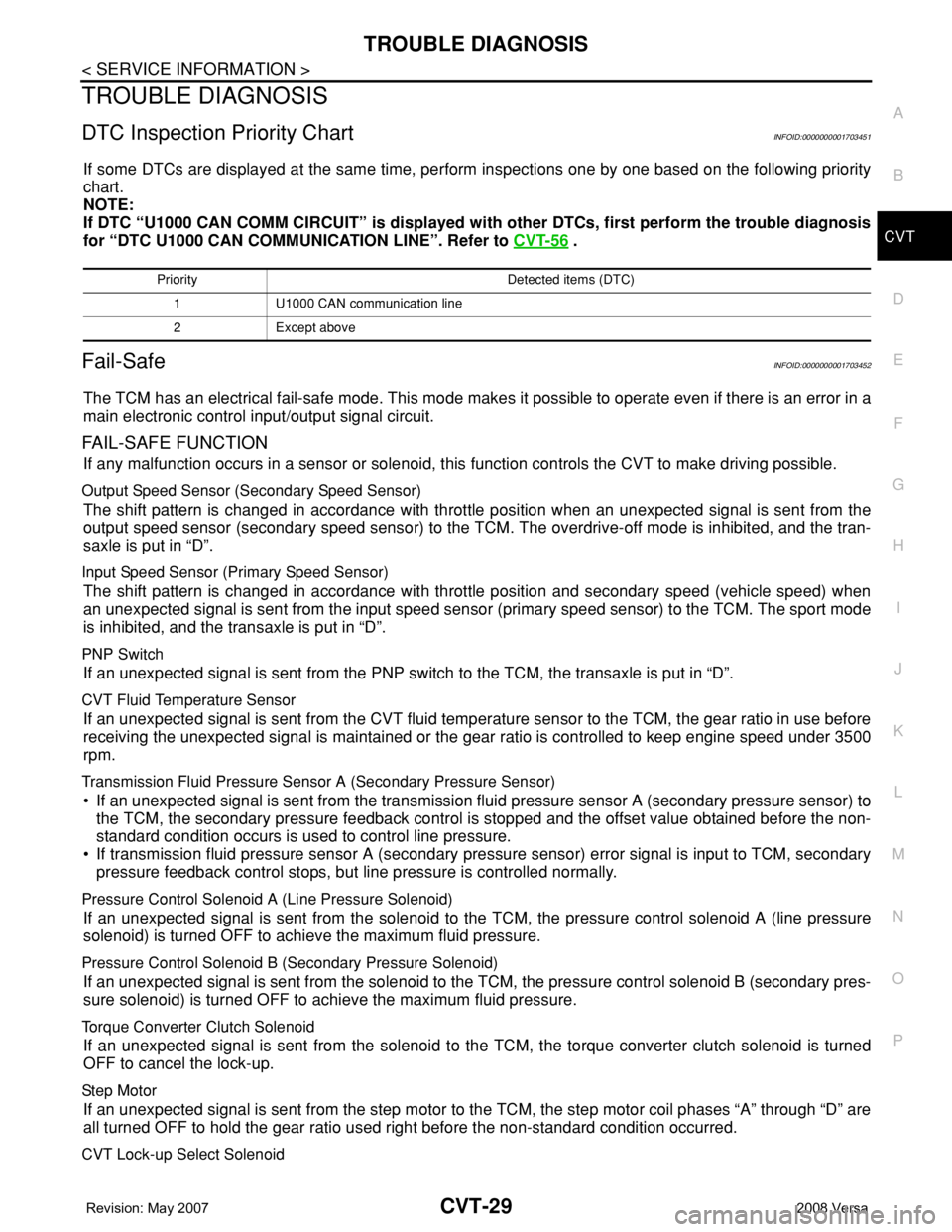
DTC Inspection Priority ChartINFOID:0000000001703451
If some DTCs are displayed at the same time, perform inspections one by one based on the following priority
chart.
NOTE:
If DTC “U1000 CAN COMM CIRCUIT” is displayed with other DTCs, first perform the trouble diagnosis
for “DTC U1000 CAN COMMUNICATION LINE”. Refer to CVT-56
.
Fail-SafeINFOID:0000000001703452
The TCM has an electrical fail-safe mode. This mode makes it possible to operate even if there is an error in a
main electronic control input/output signal circuit.
FAIL-SAFE FUNCTION
If any malfunction occurs in a sensor or solenoid, this function controls the CVT to make driving possible.
Output Speed Sensor (Secondary Speed Sensor)
The shift pattern is changed in accordance with throttle position when an unexpected signal is sent from the
output speed sensor (secondary speed sensor) to the TCM. The overdrive-off mode is inhibited, and the tran-
saxle is put in “D”.
Input Speed Sensor (Primary Speed Sensor)
The shift pattern is changed in accordance with throttle position and secondary speed (vehicle speed) when
an unexpected signal is sent from the input speed sensor (primary speed sensor) to the TCM. The sport mode
is inhibited, and the transaxle is put in “D”.
PNP Switch
If an unexpected signal is sent from the PNP switch to the TCM, the transaxle is put in “D”.
CVT Fluid Temperature Sensor
If an unexpected signal is sent from the CVT fluid temperature sensor to the TCM, the gear ratio in use before
receiving the unexpected signal is maintained or the gear ratio is controlled to keep engine speed under 3500
rpm.
Transmission Fluid Pressure Sensor A (Secondary Pressure Sensor)
• If an unexpected signal is sent from the transmission fluid pressure sensor A (secondary pressure sensor) to
the TCM, the secondary pressure feedback control is stopped and the offset value obtained before the non-
standard condition occurs is used to control line pressure.
• If transmission fluid pressure sensor A (secondary pressure sensor) error signal is input to TCM, secondary
pressure feedback control stops, but line pressure is controlled normally.
Pressure Control Solenoid A (Line Pressure Solenoid)
If an unexpected signal is sent from the solenoid to the TCM, the pressure control solenoid A (line pressure
solenoid) is turned OFF to achieve the maximum fluid pressure.
Pressure Control Solenoid B (Secondary Pressure Solenoid)
If an unexpected signal is sent from the solenoid to the TCM, the pressure control solenoid B (secondary pres-
sure solenoid) is turned OFF to achieve the maximum fluid pressure.
Torque Converter Clutch Solenoid
If an unexpected signal is sent from the solenoid to the TCM, the torque converter clutch solenoid is turned
OFF to cancel the lock-up.
Ste p M oto r
If an unexpected signal is sent from the step motor to the TCM, the step motor coil phases “A” through “D” are
all turned OFF to hold the gear ratio used right before the non-standard condition occurred.
CVT Lock-up Select Solenoid
Priority Detected items (DTC)
1 U1000 CAN communication line
2 Except above
Page 871 of 2771

CVT-32
< SERVICE INFORMATION >
TROUBLE DIAGNOSIS
Diagnostic Worksheet Chart
Customer name MR/MS Model & Year VIN
Trans. Model Engine Mileage
malfunction Date Manuf. Date In Service Date
Frequency❏ Continuous❏ Intermittent ( times a day)
Symptoms❏ Vehicle does not move. (❏ Any position❏ Particular position)
❏ No shift
❏ Lock-up malfunction
❏ Shift shock or slip (❏ N → D❏ N → R❏ Lock-up❏ Any drive position)
❏ Noise or vibration
❏ No pattern select
❏ Others
()
Malfunction indicator lamp (MIL)❏ Continuously lit❏ Not lit
1❏ Read the item on cautions concerning fail-safe and understand the customer's complaint.CVT-29
2❏ CVT fluid inspection
CVT-36❏ Leak (Repair leak location.)
❏ Sta te
❏ Amount
3❏ Stall test and line pressure test
CVT-36
,
CVT-36
❏ Stall test
❏ Torque converter one-way clutch
❏ Reverse brake
❏ Forward clutch
❏ Steel belt❏ Engine
❏ Line pressure low
❏ Primary pulley
❏ Secondary pulley
❏ Line pressure inspection - Suspected part:
Page 892 of 2771
TROUBLE DIAGNOSIS
CVT-53
< SERVICE INFORMATION >
D
E
F
G
H
I
J
K
L
MA
B
CVT
N
O
P
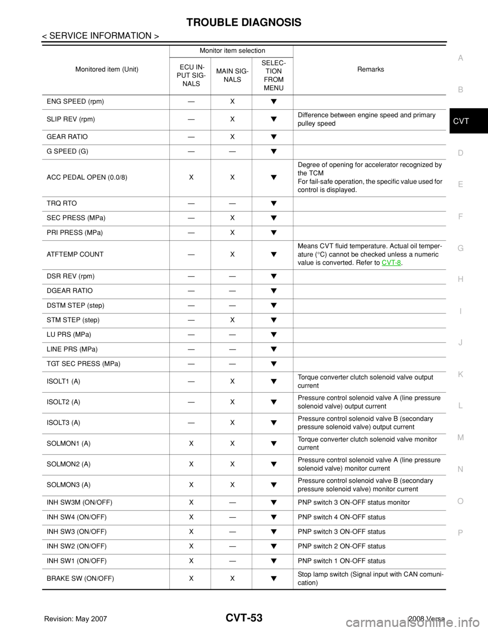
ENG SPEED (rpm) — X
SLIP REV (rpm) — XDifference between engine speed and primary
pulley speed
GEAR RATIO — X
G SPEED (G) — —
ACC PEDAL OPEN (0.0/8) X XDegree of opening for accelerator recognized by
the TCM
For fail-safe operation, the specific value used for
control is displayed.
TRQ RTO — —
SEC PRESS (MPa) — X
PRI PRESS (MPa) — X
ATFTEMP COUNT — XMeans CVT fluid temperature. Actual oil temper-
ature (°C) cannot be checked unless a numeric
value is converted. Refer to CVT-8
.
DSR REV (rpm) — —
DGEAR RATIO — —
DSTM STEP (step) — —
STM STEP (step) — X
LU PRS (MPa) — —
LINE PRS (MPa) — —
TGT SEC PRESS (MPa) — —
ISOLT1 (A) — XTorque converter clutch solenoid valve output
current
ISOLT2 (A) — XPressure control solenoid valve A (line pressure
solenoid valve) output current
ISOLT3 (A) — XPressure control solenoid valve B (secondary
pressure solenoid valve) output current
SOLMON1 (A) X XTorque converter clutch solenoid valve monitor
current
SOLMON2 (A) X XPressure control solenoid valve A (line pressure
solenoid valve) monitor current
SOLMON3 (A) X XPressure control solenoid valve B (secondary
pressure solenoid valve) monitor current
INH SW3M (ON/OFF) X — PNP switch 3 ON-OFF status monitor
INH SW4 (ON/OFF) X — PNP switch 4 ON-OFF status
INH SW3 (ON/OFF) X — PNP switch 3 ON-OFF status
INH SW2 (ON/OFF) X — PNP switch 2 ON-OFF status
INH SW1 (ON/OFF) X — PNP switch 1 ON-OFF status
BRAKE SW (ON/OFF) X XStop lamp switch (Signal input with CAN comuni-
cation) Monitored item (Unit)Monitor item selection
Remarks ECU IN-
PUT SIG-
NALSMAIN SIG-
NALSSELEC-
TION
FROM
MENU
Page 893 of 2771
CVT-54
< SERVICE INFORMATION >
TROUBLE DIAGNOSIS
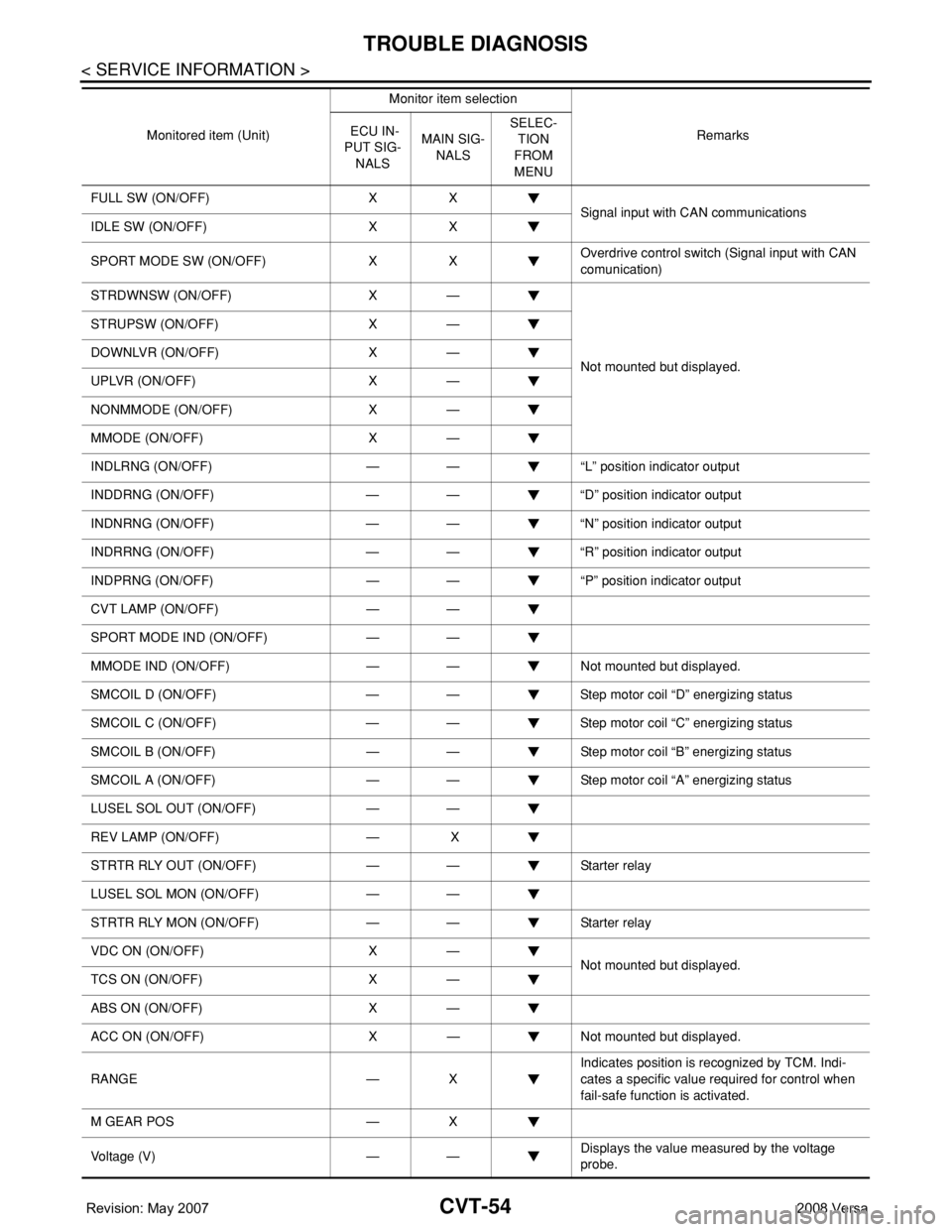
FULL SW (ON/OFF) X X
Signal input with CAN communications
IDLE SW (ON/OFF) X X
SPORT MODE SW (ON/OFF) X XOverdrive control switch (Signal input with CAN
comunication)
STRDWNSW (ON/OFF) X —
Not mounted but displayed. STRUPSW (ON/OFF) X —
DOWNLVR (ON/OFF) X —
UPLVR (ON/OFF) X —
NONMMODE (ON/OFF) X —
MMODE (ON/OFF) X —
INDLRNG (ON/OFF) — — “L” position indicator output
INDDRNG (ON/OFF) — — “D” position indicator output
INDNRNG (ON/OFF) — — “N” position indicator output
INDRRNG (ON/OFF) — — “R” position indicator output
INDPRNG (ON/OFF) — — “P” position indicator output
CVT LAMP (ON/OFF) — —
SPORT MODE IND (ON/OFF) — —
MMODE IND (ON/OFF) — — Not mounted but displayed.
SMCOIL D (ON/OFF) — — Step motor coil “D” energizing status
SMCOIL C (ON/OFF) — — Step motor coil “C” energizing status
SMCOIL B (ON/OFF) — — Step motor coil “B” energizing status
SMCOIL A (ON/OFF) — — Step motor coil “A” energizing status
LUSEL SOL OUT (ON/OFF) — —
REV LAMP (ON/OFF) — X
STRTR RLY OUT (ON/OFF) — — Starter relay
LUSEL SOL MON (ON/OFF) — —
STRTR RLY MON (ON/OFF) — — Starter relay
VDC ON (ON/OFF) X —
Not mounted but displayed.
TCS ON (ON/OFF) X —
ABS ON (ON/OFF) X —
ACC ON (ON/OFF) X — Not mounted but displayed.
RANGE — XIndicates position is recognized by TCM. Indi-
cates a specific value required for control when
fail-safe function is activated.
M GEAR POS — X
Voltage (V) — —Displays the value measured by the voltage
probe. Monitored item (Unit)Monitor item selection
Remarks ECU IN-
PUT SIG-
NALSMAIN SIG-
NALSSELEC-
TION
FROM
MENU