can NISSAN TIIDA 2008 Service Service Manual
[x] Cancel search | Manufacturer: NISSAN, Model Year: 2008, Model line: TIIDA, Model: NISSAN TIIDA 2008Pages: 2771, PDF Size: 60.61 MB
Page 90 of 2771
AT-78
< SERVICE INFORMATION >
TROUBLE DIAGNOSIS
Diagnosis Procedure without CONSULT-III
INFOID:0000000001703194
TCM SELF-DIAGNOSTIC PROCEDURE
Description
If a malfunction occurs in electrical system, turning ignition switch ON will illuminate OD OFF indicator lamp for
2 seconds. To detect a malfunction, entering a self-diagnosis start signal retrieves information on malfunctions
from memory and indicates malfunction by blinking OD OFF indicator lamp.
Diagnostic Procedure
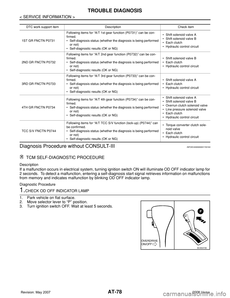
1.CHECK OD OFF INDICATOR LAMP
1. Park vehicle on flat surface.
2. Move selector lever to “P” position.
3. Turn ignition switch OFF. Wait at least 5 seconds.
DTC work support itemDescription Check item
1ST GR FNCTN P0731Following items for “A/T 1st gear function (P0731)” can be con-
firmed.
• Self-diagnosis status (whether the diagnosis is being performed
or not)
• Self-diagnostic results (OK or NG)• Shift solenoid valve A
• Shift solenoid valve B
• Each clutch
•Hydraulic control circuit
2ND GR FNCTN P0732Following items for “A/T 2nd gear function (P0732)” can be con-
firmed.
• Self-diagnosis status (whether the diagnosis is being performed
or not)
• Self-diagnostic results (OK or NG)• Shift solenoid valve B
• Each clutch
•Hydraulic control circuit
3RD GR FNCTN P0733Following items for “A/T 3rd gear function (P0733)” can be con-
firmed.
• Self-diagnosis status (whether the diagnosis is being performed
or not)
• Self-diagnostic results (OK or NG)• Shift solenoid valve A
• Each clutch
•Hydraulic control circuit
4TH GR FNCTN P0734Following items for “A/T 4th gear function (P0734)” can be con-
firmed.
• Self-diagnosis status (whether the diagnosis is being performed
or not)
• Self-diagnostic results (OK or NG)• Shift solenoid valve A
• Shift solenoid valve B
• Overrun clutch solenoid valve
• Line pressure solenoid valve
• Each clutch
•Hydraulic control circuit
TCC S/V FNCTN P0744Following items for “A/T TCC S/V function (lock-up) (P0744)” can
be confirmed.
• Self-diagnosis status (whether the diagnosis is being performed
or not)
• Self-diagnostic results (OK or NG)• Torque converter clutch sole-
noid valve
• Each clutch
•Hydraulic control circuit
SCIA5472E
Page 92 of 2771
AT-80
< SERVICE INFORMATION >
TROUBLE DIAGNOSIS
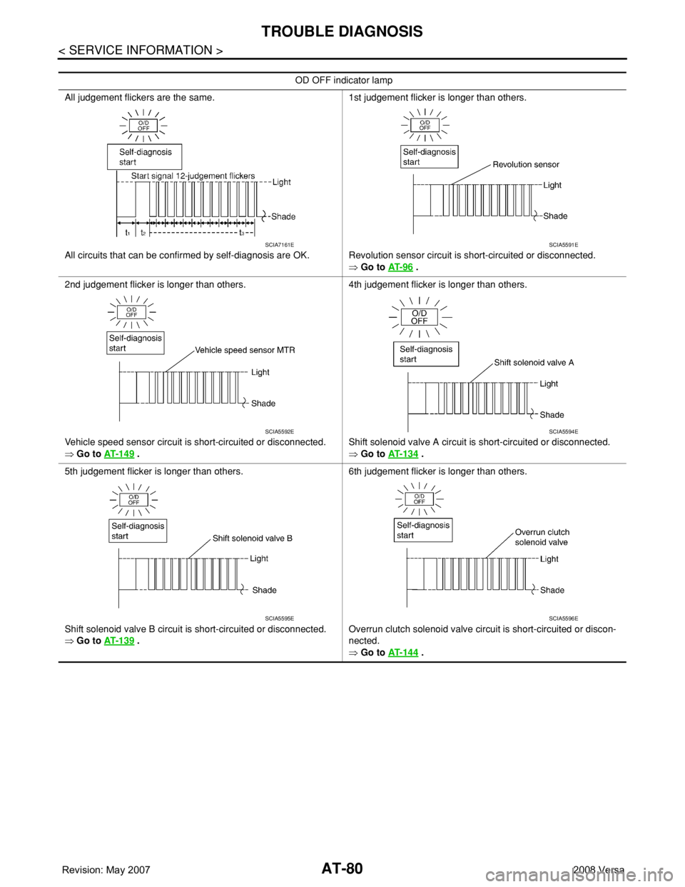
OD OFF indicator lamp
All judgement flickers are the same.
All circuits that can be confirmed by self-diagnosis are OK.1st judgement flicker is longer than others.
Revolution sensor circuit is short-circuited or disconnected.
⇒ Go to AT- 9 6
.
2nd judgement flicker is longer than others.
Vehicle speed sensor circuit is short-circuited or disconnected.
⇒ Go to AT- 1 4 9
.4th judgement flicker is longer than others.
Shift solenoid valve A circuit is short-circuited or disconnected.
⇒ Go to AT- 1 3 4 .
5th judgement flicker is longer than others.
Shift solenoid valve B circuit is short-circuited or disconnected.
⇒ Go to AT- 1 3 9
.6th judgement flicker is longer than others.
Overrun clutch solenoid valve circuit is short-circuited or discon-
nected.
⇒ Go to AT- 1 4 4
.
SCIA7161ESCIA5591E
SCIA5592ESCIA5594E
SCIA5595ESCIA5596E
Page 94 of 2771
AT-82
< SERVICE INFORMATION >
TROUBLE DIAGNOSIS
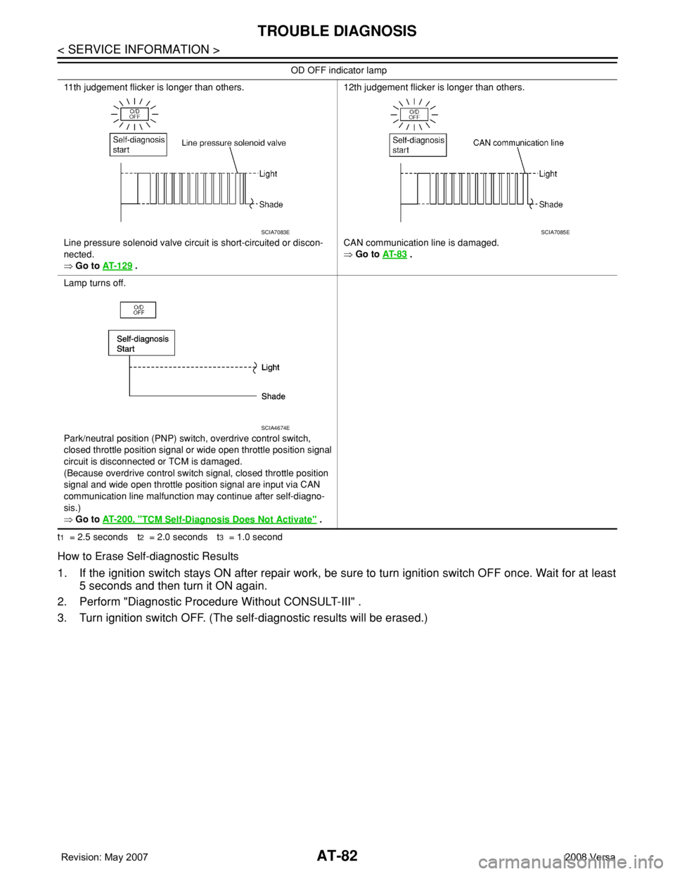
t1 = 2.5 seconds t2 = 2.0 seconds t3 = 1.0 second
How to Erase Self-diagnostic Results
1. If the ignition switch stays ON after repair work, be sure to turn ignition switch OFF once. Wait for at least
5 seconds and then turn it ON again.
2. Perform "Diagnostic Procedure Without CONSULT-III" .
3. Turn ignition switch OFF. (The self-diagnostic results will be erased.)
11th judgement flicker is longer than others.
Line pressure solenoid valve circuit is short-circuited or discon-
nected.
⇒ Go to AT- 1 2 9
.12th judgement flicker is longer than others.
CAN communication line is damaged.
⇒ Go to AT- 8 3
.
Lamp turns off.
Park/neutral position (PNP) switch, overdrive control switch,
closed throttle position signal or wide open throttle position signal
circuit is disconnected or TCM is damaged.
(Because overdrive control switch signal, closed throttle position
signal and wide open throttle position signal are input via CAN
communication line malfunction may continue after self-diagno-
sis.)
⇒ Go to AT- 2 0 0 , "
TCM Self-Diagnosis Does Not Activate" . OD OFF indicator lamp
SCIA7083ESCIA7085E
SCIA4674E
Page 95 of 2771
DTC U1000 CAN COMMUNICATION LINE
AT-83
< SERVICE INFORMATION >
D
E
F
G
H
I
J
K
L
MA
B
AT
N
O
P
DTC U1000 CAN COMMUNICATION LINE
DescriptionINFOID:0000000001703195
CAN (Controller Area Network) is a serial communication line for real time application. It is an on-vehicle mul-
tiplex communication line with high data communication speed and excellent malfunction detection ability.
Many electronic control units are equipped onto a vehicle, and each control unit shares information and links
with other control units during operation (not independent). In CAN communication, control units are con-
nected with 2 communication lines (CAN H line, CAN L line) allowing a high rate of information transmission
with less wiring. Each control unit transmits/receives data but selectively reads required data only.
On Board Diagnosis LogicINFOID:0000000001703196
• This is an OBD-II self-diagnostic item.
• Diagnostic trouble code “U1000 CAN COMM CIRCUIT” with CONSULT-III or 12th judgement flicker without
CONSULT-III is detected when TCM cannot communicate to other control units.
Possible CauseINFOID:0000000001703197
Harness or connector
(CAN communication line is open or shorted.)
DTC Confirmation ProcedureINFOID:0000000001703198
CAUTION:
If performing this “DTC Confirmation Procedure” again, always turn ignition switch OFF and wait at
least 10 seconds before continuing.
After the repair, perform the following procedure to confirm the malfunction is eliminated.
WITH CONSULT-III
1. Turn ignition switch ON.
2. Select “DATA MONITOR” mode for “A/T” with CONSULT-III.
3. Touch “START”.
4. Wait at least 6 seconds or start engine and wait for at least 6 seconds.
5. If DTC is detected, go to AT-85, "
Diagnosis Procedure".
WITH GST
Follow the procedure “WITH CONSULT-III”.
WITHOUT CONSULT-III
1. Turn ignition switch ON.
2. Wait at least 6 seconds or start engine and wait at least 6 seconds.
3. Perform self-diagnosis. Refer to AT-78, "
Diagnosis Procedure without CONSULT-III".
4. If DTC is detected, go to AT-85, "
Diagnosis Procedure".
Page 96 of 2771
AT-84
< SERVICE INFORMATION >
DTC U1000 CAN COMMUNICATION LINE
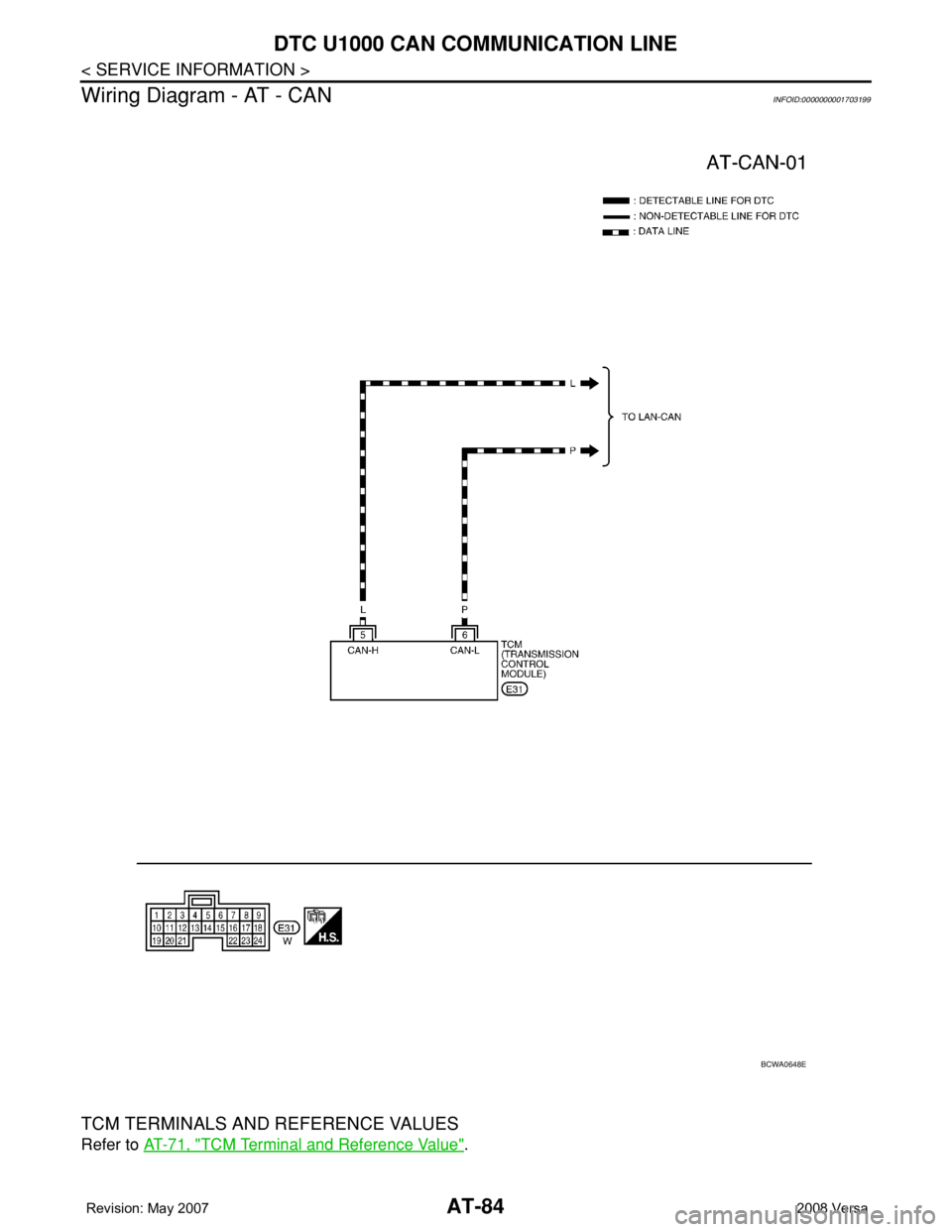
Wiring Diagram - AT - CAN
INFOID:0000000001703199
TCM TERMINALS AND REFERENCE VALUES
Refer to AT-71, "TCM Terminal and Reference Value".
BCWA0648E
Page 97 of 2771

DTC U1000 CAN COMMUNICATION LINE
AT-85
< SERVICE INFORMATION >
D
E
F
G
H
I
J
K
L
MA
B
AT
N
O
P
Diagnosis ProcedureINFOID:0000000001703200
1.CHECK CAN COMMUNICATION CIRCUIT
With CONSULT-III1. Turn ignition switch ON and start engine.
2. Select “SELF-DIAG RESULTS” mode for “A/T” with CONSULT-III.
Is any malfunction of the
“U1000 CAN COMM CIRCUIT” indicated?
YES >> Print out CONSULT-III screen, Go to LAN section. Refer to LAN-23, "CAN System Specification
Chart".
NO >>INSPECTION END
Page 110 of 2771
AT-98
< SERVICE INFORMATION >
DTC P0720 VEHICLE SPEED SENSOR A/T (REVOLUTION SENSOR)
TCM TERMINALS AND REFERENCE VALUES
Refer to AT-71, "TCM Terminal and Reference Value".
Diagnosis ProcedureINFOID:0000000001703223
1.CHECK INPUT SIGNAL
With CONSULT-III
1. Start engine.
2. Select “TCM INPUT SIGNALS” in “DATA MONITOR” mode for “A/T” with CONSULT-III.
3. Read out the value of “VHCL/S SE-A/T” while driving.
Check the value changes according to driving speed.
OK or NG
OK >> GO TO 8.
NG >> GO TO 2.
2. CHECK REVOLUTION SENSOR
With CONSULT-III
1. Start engine.
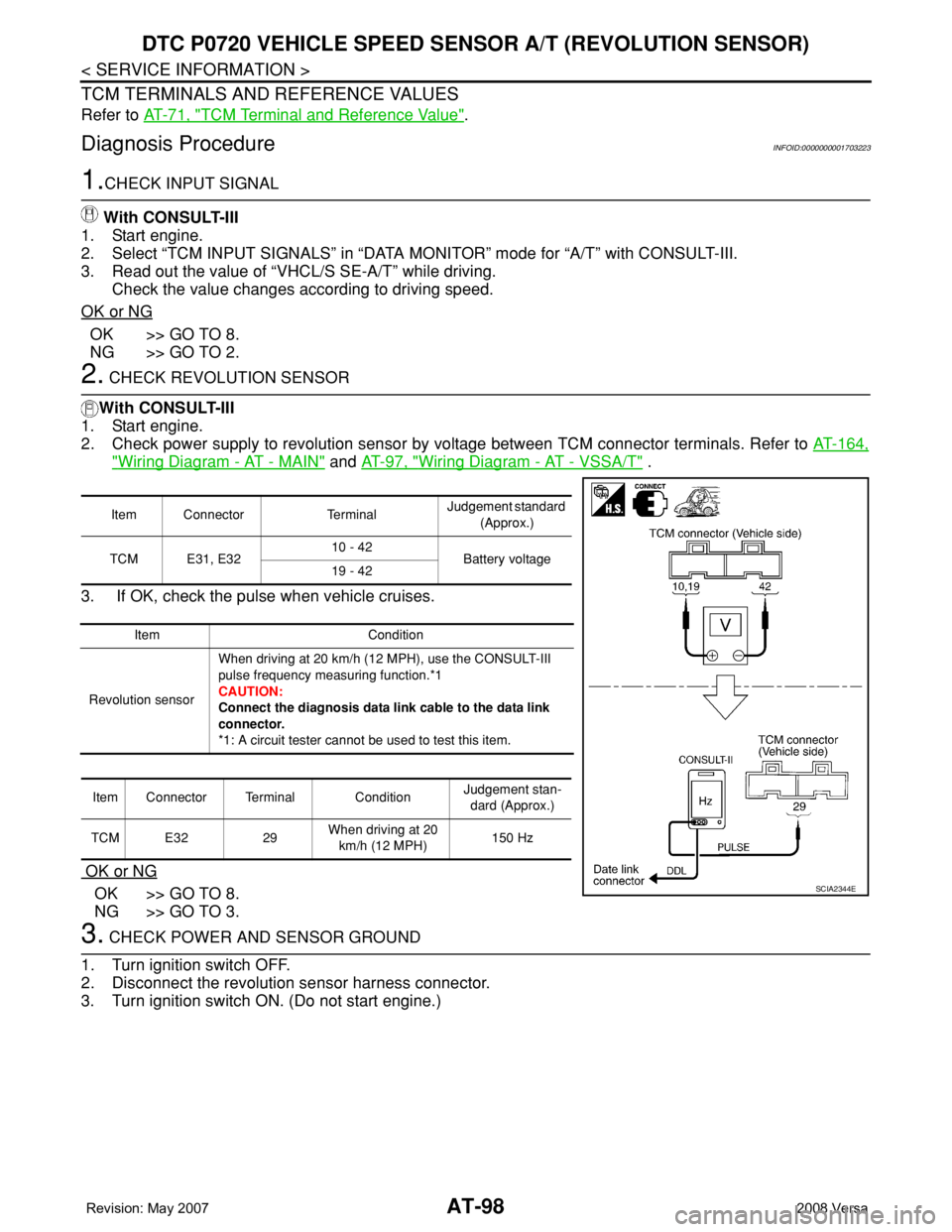
2. Check power supply to revolution sensor by voltage between TCM connector terminals. Refer to AT-164,
"Wiring Diagram - AT - MAIN" and AT-97, "Wiring Diagram - AT - VSSA/T" .
3. If OK, check the pulse when vehicle cruises.
OK or NG
OK >> GO TO 8.
NG >> GO TO 3.
3. CHECK POWER AND SENSOR GROUND
1. Turn ignition switch OFF.
2. Disconnect the revolution sensor harness connector.
3. Turn ignition switch ON. (Do not start engine.)
Item Connector TerminalJudgement standard
(Approx.)
TCM E31, E3210 - 42
Battery voltage
19 - 42
Item Condition
Revolution sensorWhen driving at 20 km/h (12 MPH), use the CONSULT-III
pulse frequency measuring function.*1
CAUTION:
Connect the diagnosis data link cable to the data link
connector.
*1: A circuit tester cannot be used to test this item.
Item Connector Terminal ConditionJudgement stan-
dard (Approx.)
TCM E32 29When driving at 20
km/h (12 MPH)150 Hz
SCIA2344E
Page 117 of 2771

DTC P0731 A/T 1ST GEAR FUNCTION
AT-105
< SERVICE INFORMATION >
D
E
F
G
H
I
J
K
L
MA
B
AT
N
O
P
DTC P0731 A/T 1ST GEAR FUNCTION
DescriptionINFOID:0000000001703231
• This malfunction will not be detected while the OD OFF indicator lamp is indicating another self-diagnosis
malfunction.
• This malfunction is detected when the A/T does not shift into first gear position as instructed by the TCM.
This is not caused by electrical malfunction (circuits open or shorted) but by mechanical malfunction such as
control valve sticking, improper solenoid valve operation, etc.
On Board Diagnosis LogicINFOID:0000000001703232
• This is an OBD-II self-diagnostic item.
• Diagnostic trouble code “P0731 A/T 1ST GR FNCTN” with CONSULT-III is detected when A/T cannot be
shifted to the 1st gear position even if electrical circuit is good.
• This diagnosis monitors actual gear position by checking the torque converter slip ratio calculated by TCM
as follows:
Torque converter slip ratio = A x C/B
A: Output shaft revolution signal from revolution sensor
B: Engine speed signal from ECM
C: Gear ratio determined as gear position which TCM supposes
If the actual gear position is higher than the position (1st) supposed by TCM, the slip ratio will be more than
normal. In case the ratio exceeds the specified value, TCM judges this diagnosis malfunction.
This malfunction will be caused when either shift solenoid valve A is stuck open or shift solenoid valve B is
stuck open.
• Gear positions supposed by TCM are as follows:
In case of gear position with no malfunctions: 1, 2, 3 and 4 positions
In case of gear position with shift solenoid valve A stuck open: 2*, 2, 3 and 3 positions
In case of gear position with shift solenoid valve B stuck open: 4*, 3, 3 and 4 positions to each gear position
above
*: “P0731 A/T 1ST GR FNCTN” is detected.
Possible CauseINFOID:0000000001703233
• Shift solenoid valve A
• Shift solenoid valve B
• Each clutch
• Hydraulic control circuit
DTC Confirmation ProcedureINFOID:0000000001703234
CAUTION:
• Always drive vehicle at a safe speed.
• If performing this “DTC Confirmation Procedure” again, always turn ignition switch OFF and wait at
least 10 seconds before continuing.
After the repair, perform the following procedure to confirm the malfunction is eliminated.
WITH CONSULT-III
1. Start engine and select “DATA MONITOR” mode for “A/T” with CONSULT-III.
2. Touch “START”.
3. Make sure that output voltage of A/T fluid temperature sensor is within the range below.
FLUID TEMP SE: 0.4 - 1.5 V
If out of range, drive the vehicle to decrease the voltage (warm up the fluid) or stop engine to increase the
voltage (cool down the fluid).
4. Select “1ST GR FNCTN P0731” of “DTC WORK SUPPORT” mode for “A/T” with CONSULT-III and touch
“START”.
Gear position 1 2 3 4
Shift solenoid valve A ON (Closed) OFF (Open) OFF (Open) ON (Closed)
Shift solenoid valve B ON (Closed) ON (Closed) OFF (Open) OFF (Open)
Page 120 of 2771

AT-108
< SERVICE INFORMATION >
DTC P0732 A/T 2ND GEAR FUNCTION
DTC P0732 A/T 2ND GEAR FUNCTION
DescriptionINFOID:0000000001703236
• This malfunction will not be detected while the OD OFF indicator lamp is indicating another self-diagnosis
malfunction.
• This malfunction is detected when the A/T does not shift into second gear position as instructed by the TCM.
This is not caused by electrical malfunction (circuits open or shorted) but by mechanical malfunction such as
control valve sticking, improper solenoid valve operation, etc.
On Board Diagnosis LogicINFOID:0000000001703237
• This is an OBD-II self-diagnostic item.
• Diagnostic trouble code “P0732 A/T 2ND GR FNCTN” with CONSULT-III is detected when A/T cannot be
shifted to the 2nd gear position even if electrical circuit is good.
• This diagnosis monitors actual gear position by checking the torque converter slip ratio calculated by TCM
as follows:
Torque converter slip ratio = A x C/B
A: Output shaft revolution signal from revolution sensor
B: Engine speed signal from ECM
C: Gear ratio determined as gear position which TCM supposes
If the actual gear position is higher than the position (2nd) supposed by TCM, the slip ratio will be more than
normal. In case the ratio exceeds the specified value, TCM judges this diagnosis malfunction.
This malfunction will be caused when shift solenoid valve B is stuck open.
• Gear positions supposed by TCM are as follows:
In case of gear position with no malfunctions: 1, 2, 3 and 4 positions
In case of gear position with shift solenoid valve B stuck open: 4, 3*, 3 and 4 positions to each gear position
above
*: “P0732 A/T 2ND GR FNCTN” is detected.
Possible CauseINFOID:0000000001703238
• Shift solenoid valve B
• Each clutch
• Hydraulic control circuit
DTC Confirmation ProcedureINFOID:0000000001703239
CAUTION:
• Always drive vehicle at a safe speed.
• If performing this “DTC Confirmation Procedure” again, always turn ignition switch OFF and wait at
least 10 seconds before continuing.
After the repair, perform the following procedure to confirm the malfunction is eliminated.
WITH CONSULT-III
1. Start engine and select “DATA MONITOR” mode for “A/T” with CONSULT-III.
2. Touch “START”.
3. Make sure that output voltage of A/T fluid temperature sensor is within the range below.
FLUID TEMP SE: 0.4 - 1.5 V
If out of range, drive the vehicle to decrease the voltage (warm up the fluid) or stop engine to increase the
voltage (cool down the fluid).
4. Select “2ND GR FNCTN P0732” of “DTC WORK SUPPORT” mode for “A/T” with CONSULT-III and touch
“START”.
5. Accelerate vehicle to 45 to 50 km/h (28 to 31 MPH) under the following conditions and release the accel-
erator pedal completely.
THROTTLE POSI: Less than 1.0/8
SLCT LVR POSI: “D” position
Gear position 1 2 3 4
Shift solenoid valve A ON (Closed) OFF (Open) OFF (Open) ON (Closed)
Shift solenoid valve B ON (Closed)ON (Closed) OFF (Open) OFF (Open)
Page 123 of 2771

DTC P0733 A/T 3RD GEAR FUNCTION
AT-111
< SERVICE INFORMATION >
D
E
F
G
H
I
J
K
L
MA
B
AT
N
O
P
DTC P0733 A/T 3RD GEAR FUNCTION
DescriptionINFOID:0000000001703241
• This malfunction will not be detected while the OD OFF indicator lamp is indicating another self-diagnosis
malfunction.
• This malfunction is detected when the A/T does not shift into third gear position as instructed by the TCM.
This is not caused by electrical malfunction (circuits open or shorted) but by mechanical malfunction such as
control valve sticking, improper solenoid valve operation, malfunctioning servo piston or brake band, etc.
On Board Diagnosis LogicINFOID:0000000001703242
• This is an OBD-II self-diagnostic item.
• Diagnostic trouble code “P0733 A/T 3RD GR FNCTN” with CONSULT-III is detected when A/T cannot be
shifted to the 3rd gear position even if electrical circuit is good.
• This diagnosis monitors actual gear position by checking the torque converter slip ratio calculated by TCM
as follows:
Torque converter slip ratio = A x C/B
A: Output shaft revolution signal from revolution sensor
B: Engine speed signal from ECM
C: Gear ratio determined as gear position which TCM supposes
If the actual gear position is higher than the position (3rd) supposed by TCM, the slip ratio will be more than
normal. In case the ratio exceeds the specified value, TCM judges this diagnosis malfunction.
This malfunction will be caused when shift solenoid valve A is stuck closed.
• Gear positions supposed by TCM are as follows.
In case of gear position with no malfunctions: 1, 2, 3 and 4 positions
In case of gear position with shift solenoid valve A stuck closed: 1, 1, 4* and 4 positions to each gear position
above
*: “P0733 A/T 3RD GR FNCTN” is detected.
Possible CauseINFOID:0000000001703243
• Shift solenoid valve A
• Each clutch
• Hydraulic control circuit
DTC Confirmation ProcedureINFOID:0000000001703244
CAUTION:
• Always drive vehicle at a safe speed.
• If performing this “DTC Confirmation Procedure” again, always turn ignition switch OFF and wait at
least 10 seconds before continuing.
After the repair, perform the following procedure to confirm the malfunction is eliminated.
WITH CONSULT-III
1. Start engine and select “DATA MONITOR” mode for “A/T” with CONSULT-III.
2. Touch “START”.
3. Make sure that output voltage of A/T fluid temperature sensor is within the range below.
FLUID TEMP SE: 0.4 - 1.5 V
If out of range, drive the vehicle to decrease the voltage (warm up the fluid) or stop engine to increase the
voltage (cool down the fluid).
4. Select “3RD GR FNCTN P0733” of “DTC WORK SUPPORT” mode for “A/T” with CONSULT-III and touch
“START”.
5. Accelerate vehicle to 60 to 75 km/h (37 to 47 MPH) under the following conditions and release the accel-
erator pedal completely.
THROTTLE POSI: Less than 1.0/8 (at all times during step 4)
SLCT LVR POSI: “D” position
Gear position 1 2 3 4
Shift solenoid valve A ON (Closed) OFF (Open) OFF (Open) ON (Closed)
Shift solenoid valve B ON (Closed) ON (Closed) OFF (Open) OFF (Open)