can NISSAN TIIDA 2008 Service User Guide
[x] Cancel search | Manufacturer: NISSAN, Model Year: 2008, Model line: TIIDA, Model: NISSAN TIIDA 2008Pages: 2771, PDF Size: 60.61 MB
Page 27 of 2771
A/T FLUID
AT-15
< SERVICE INFORMATION >
D
E
F
G
H
I
J
K
L
MA
B
AT
N
O
P
A/T FLUID
Checking A/T FluidINFOID:0000000001703158
1. Warm up engine.
2. Check for A/T fluid leakage.
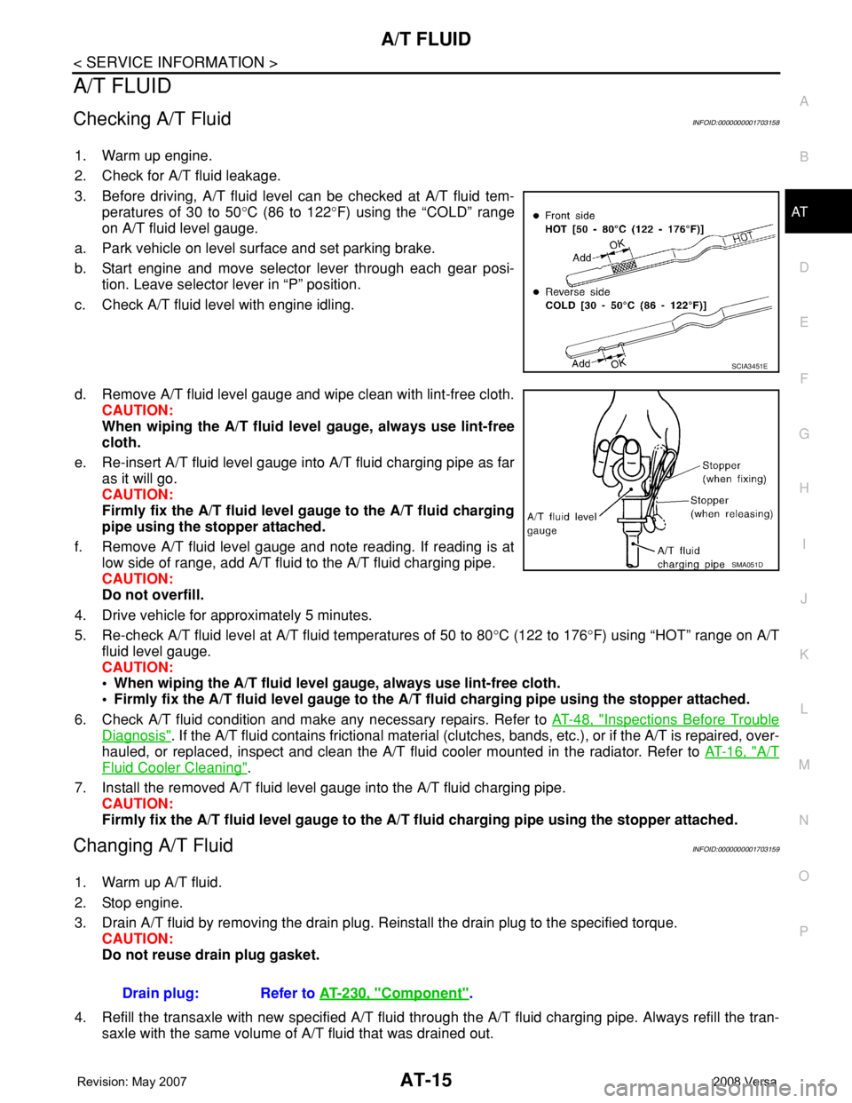
3. Before driving, A/T fluid level can be checked at A/T fluid tem-
peratures of 30 to 50°C (86 to 122°F) using the “COLD” range
on A/T fluid level gauge.
a. Park vehicle on level surface and set parking brake.
b. Start engine and move selector lever through each gear posi-
tion. Leave selector lever in “P” position.
c. Check A/T fluid level with engine idling.
d. Remove A/T fluid level gauge and wipe clean with lint-free cloth.
CAUTION:
When wiping the A/T fluid level gauge, always use lint-free
cloth.
e. Re-insert A/T fluid level gauge into A/T fluid charging pipe as far
as it will go.
CAUTION:
Firmly fix the A/T fluid level gauge to the A/T fluid charging
pipe using the stopper attached.
f. Remove A/T fluid level gauge and note reading. If reading is at
low side of range, add A/T fluid to the A/T fluid charging pipe.
CAUTION:
Do not overfill.
4. Drive vehicle for approximately 5 minutes.
5. Re-check A/T fluid level at A/T fluid temperatures of 50 to 80°C (122 to 176°F) using “HOT” range on A/T
fluid level gauge.
CAUTION:
• When wiping the A/T fluid level gauge, always use lint-free cloth.
• Firmly fix the A/T fluid level gauge to the A/T fluid charging pipe using the stopper attached.
6. Check A/T fluid condition and make any necessary repairs. Refer to AT-48, "
Inspections Before Trouble
Diagnosis". If the A/T fluid contains frictional material (clutches, bands, etc.), or if the A/T is repaired, over-
hauled, or replaced, inspect and clean the A/T fluid cooler mounted in the radiator. Refer to AT-16, "
A/T
Fluid Cooler Cleaning".
7. Install the removed A/T fluid level gauge into the A/T fluid charging pipe.
CAUTION:
Firmly fix the A/T fluid level gauge to the A/T fluid charging pipe using the stopper attached.
Changing A/T FluidINFOID:0000000001703159
1. Warm up A/T fluid.
2. Stop engine.
3. Drain A/T fluid by removing the drain plug. Reinstall the drain plug to the specified torque.
CAUTION:
Do not reuse drain plug gasket.
4. Refill the transaxle with new specified A/T fluid through the A/T fluid charging pipe. Always refill the tran-
saxle with the same volume of A/T fluid that was drained out.
SCIA3451E
SMA051D
Drain plug: Refer to AT-230, "Component".
Page 28 of 2771
AT-16
< SERVICE INFORMATION >
A/T FLUID
5. Run engine at idle speed for 5 minutes.
6. Check A/T fluid level and condition. Refer to MA-22, "
Checking A/T Fluid".
A/T Fluid Cooler CleaningINFOID:0000000001703160
Whenever the A/T is repaired, overhauled, or replaced, the A/T fluid cooler mounted in the radiator must be
inspected and cleaned.
Metal debris and friction material, if present, can become trapped in the A/T fluid cooler. This debris can con-
taminate the newly serviced A/T or, in severe cases, can block or restrict the flow of A/T fluid. In either case,
malfunction of the newly serviced A/T may result.
Debris, if present, may build up as A/T fluid enters the cooler inlet. It will be necessary to back flush the cooler
through the cooler outlet in order to flush out any built up debris.
A/T FLUID COOLER CLEANING PROCEDURE
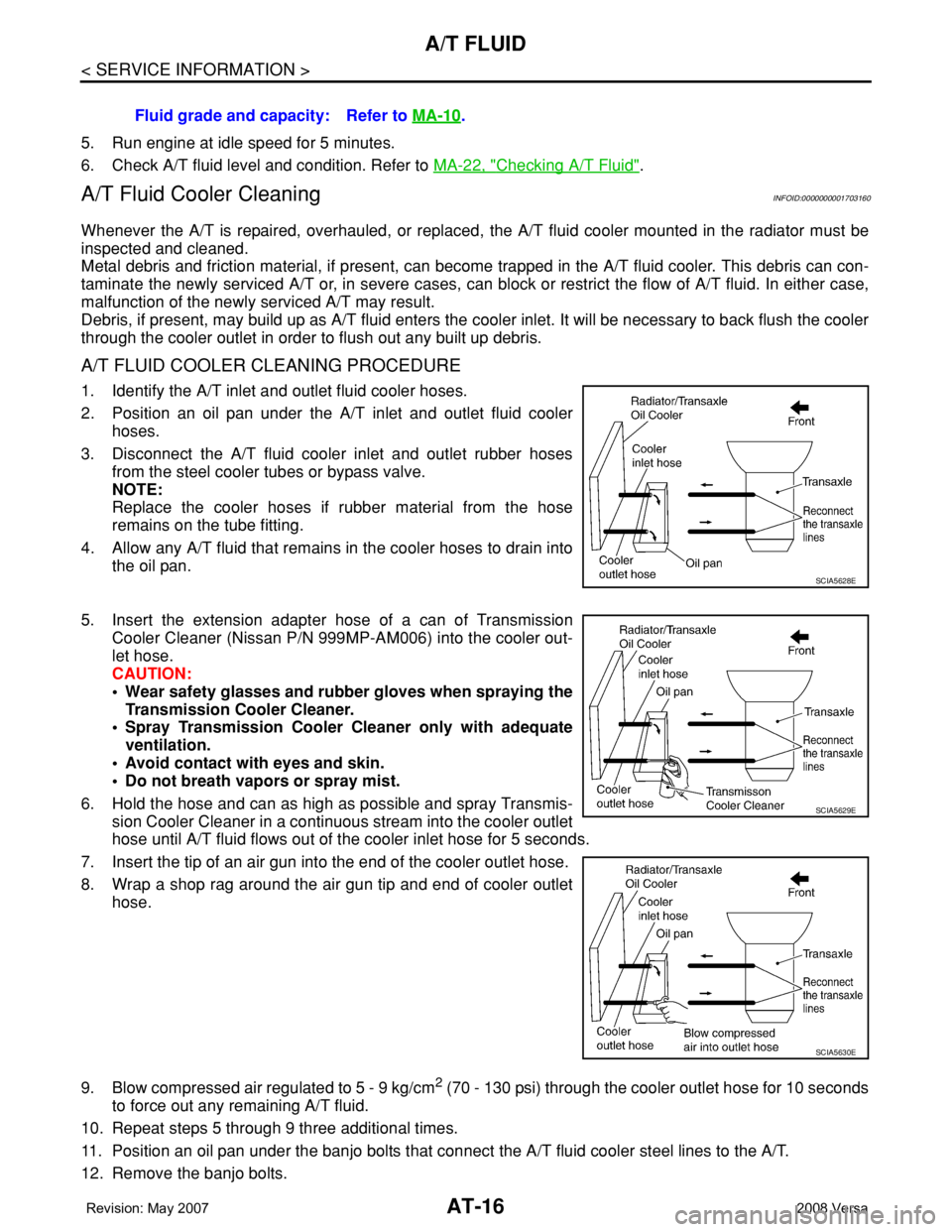
1. Identify the A/T inlet and outlet fluid cooler hoses.
2. Position an oil pan under the A/T inlet and outlet fluid cooler
hoses.
3. Disconnect the A/T fluid cooler inlet and outlet rubber hoses
from the steel cooler tubes or bypass valve.
NOTE:
Replace the cooler hoses if rubber material from the hose
remains on the tube fitting.
4. Allow any A/T fluid that remains in the cooler hoses to drain into
the oil pan.
5. Insert the extension adapter hose of a can of Transmission
Cooler Cleaner (Nissan P/N 999MP-AM006) into the cooler out-
let hose.
CAUTION:
• Wear safety glasses and rubber gloves when spraying the
Transmission Cooler Cleaner.
• Spray Transmission Cooler Cleaner only with adequate
ventilation.
• Avoid contact with eyes and skin.
• Do not breath vapors or spray mist.
6. Hold the hose and can as high as possible and spray Transmis-
sion Cooler Cleaner in a continuous stream into the cooler outlet
hose until A/T fluid flows out of the cooler inlet hose for 5 seconds.
7. Insert the tip of an air gun into the end of the cooler outlet hose.
8. Wrap a shop rag around the air gun tip and end of cooler outlet
hose.
9. Blow compressed air regulated to 5 - 9 kg/cm
2 (70 - 130 psi) through the cooler outlet hose for 10 seconds
to force out any remaining A/T fluid.
10. Repeat steps 5 through 9 three additional times.
11. Position an oil pan under the banjo bolts that connect the A/T fluid cooler steel lines to the A/T.
12. Remove the banjo bolts.Fluid grade and capacity: Refer to MA-10
.
SCIA5628E
SCIA5629E
SCIA5630E
Page 29 of 2771
A/T FLUID
AT-17
< SERVICE INFORMATION >
D
E
F
G
H
I
J
K
L
MA
B
AT
N
O
P
13. Flush each steel line from the cooler side back toward the A/T by spraying Transmission Cooler Cleaner
in a continuous stream for 5 seconds.
14. Blow compressed air regulated to 5 - 9 kg/cm
2 (70 - 130 psi) through each steel line from the cooler side
back toward the A/T for 10 seconds to force out any remaining A/T fluid.
15. Ensure all debris is removed from the steel cooler lines.
16. Ensure all debris is removed from the banjo bolts and fittings.
17. Perform "A/T FLUID COOLER DIAGNOSIS PROCEDURE".
A/T FLUID COOLER DIAGNOSIS PROCEDURE
NOTE:
Insufficient cleaning of the cooler inlet hose exterior may lead to inaccurate debris identification.
1. Position an oil pan under the A/T inlet and outlet cooler hoses.
2. Clean the exterior and tip of the cooler inlet hose.
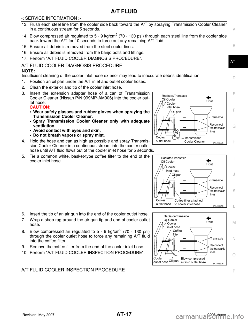
3. Insert the extension adapter hose of a can of Transmission
Cooler Cleaner (Nissan P/N 999MP-AM006) into the cooler out-
let hose.
CAUTION:
• Wear safety glasses and rubber gloves when spraying the
Transmission Cooler Cleaner.
• Spray Transmission Cooler Cleaner only with adequate
ventilation.
• Avoid contact with eyes and skin.
• Do not breath vapors or spray mist.
4. Hold the hose and can as high as possible and spray Transmis-
sion Cooler Cleaner in a continuous stream into the cooler outlet
hose until A/T fluid flows out of the cooler inlet hose for 5 seconds.
5. Tie a common white, basket-type coffee filter to the end of the
cooler inlet hose.
6. Insert the tip of an air gun into the end of the cooler outlet hose.
7. Wrap a shop rag around the air gun tip and end of cooler outlet
hose.
8. Blow compressed air regulated to 5 - 9 kg/cm
2 (70 - 130 psi)
through the cooler outlet hose to force any remaining A/T fluid
into the coffee filter.
9. Remove the coffee filter from the end of the cooler inlet hose.
10. Perform "A/T FLUID COOLER INSPECTION PROCEDURE".
A/T FLUID COOLER INSPECTION PROCEDURE
SCIA5629E
SCIA5631E
SCIA5632E
Page 30 of 2771
AT-18
< SERVICE INFORMATION >
A/T FLUID
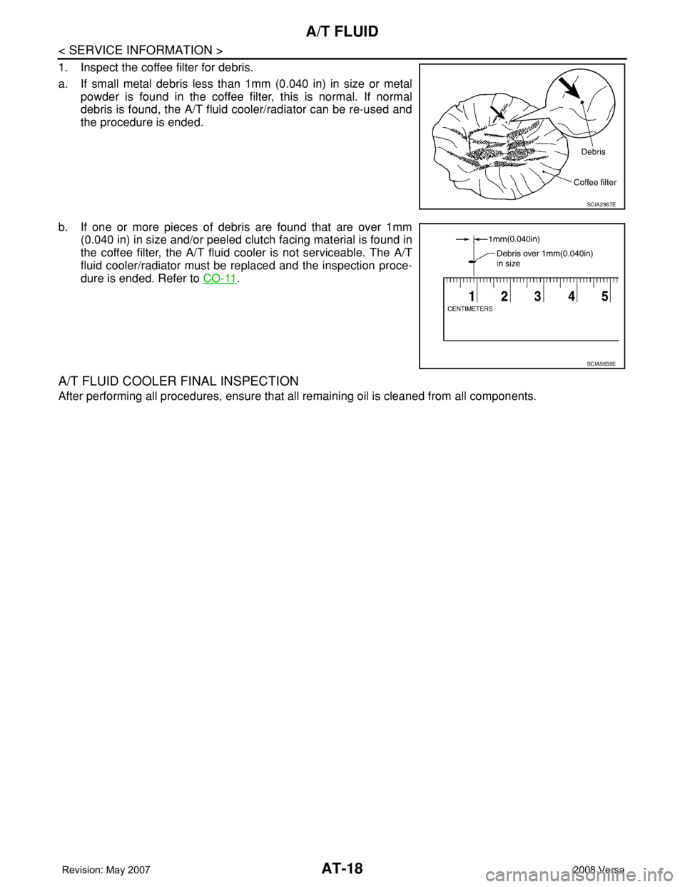
1. Inspect the coffee filter for debris.
a. If small metal debris less than 1mm (0.040 in) in size or metal
powder is found in the coffee filter, this is normal. If normal
debris is found, the A/T fluid cooler/radiator can be re-used and
the procedure is ended.
b. If one or more pieces of debris are found that are over 1mm
(0.040 in) in size and/or peeled clutch facing material is found in
the coffee filter, the A/T fluid cooler is not serviceable. The A/T
fluid cooler/radiator must be replaced and the inspection proce-
dure is ended. Refer to CO-11
.
A/T FLUID COOLER FINAL INSPECTION
After performing all procedures, ensure that all remaining oil is cleaned from all components.
SCIA2967E
SCIA5659E
Page 34 of 2771
AT-22
< SERVICE INFORMATION >
A/T CONTROL SYSTEM
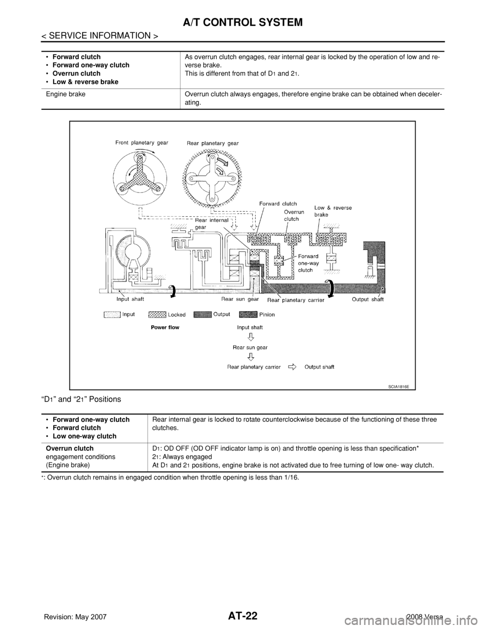
“D1” and “21” Positions
*: Overrun clutch remains in engaged condition when throttle opening is less than 1/16.•Forward clutch
•Forward one-way clutch
•Overrun clutch
•Low & reverse brakeAs overrun clutch engages, rear internal gear is locked by the operation of low and re-
verse brake.
This is different from that of D
1 and 21.
Engine brake Overrun clutch always engages, therefore engine brake can be obtained when deceler-
ating.
SCIA1816E
•Forward one-way clutch
•Forward clutch
•Low one-way clutchRear internal gear is locked to rotate counterclockwise because of the functioning of these three
clutches.
Overrun clutch
engagement conditions
(Engine brake)D
1: OD OFF (OD OFF indicator lamp is on) and throttle opening is less than specification*
2
1: Always engaged
At D
1 and 21 positions, engine brake is not activated due to free turning of low one- way clutch.
Page 37 of 2771
A/T CONTROL SYSTEM
AT-25
< SERVICE INFORMATION >
D
E
F
G
H
I
J
K
L
MA
B
AT
N
O
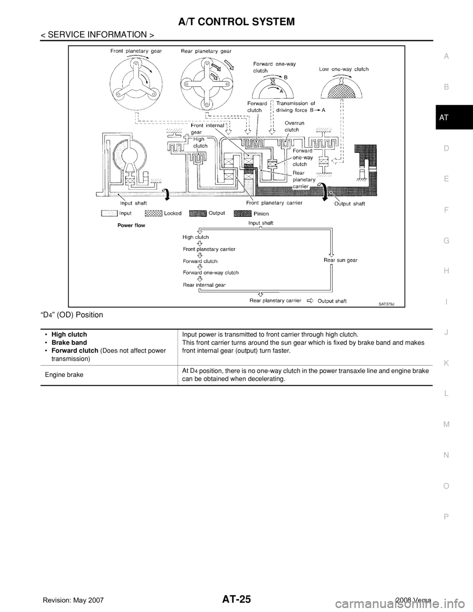
P “D
4” (OD) Position
SAT379J
•High clutch
•Brake band
•Forward clutch (Does not affect power
transmission)Input power is transmitted to front carrier through high clutch.
This front carrier turns around the sun gear which is fixed by brake band and makes
front internal gear (output) turn faster.
Engine brakeAt D
4 position, there is no one-way clutch in the power transaxle line and engine brake
can be obtained when decelerating.
Page 38 of 2771
AT-26
< SERVICE INFORMATION >
A/T CONTROL SYSTEM
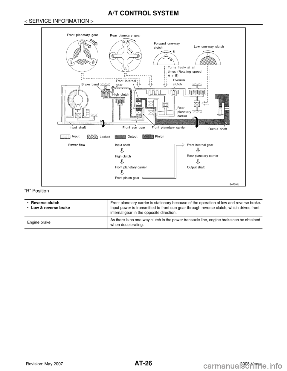
“R” Position
SAT380J
•Reverse clutch
•Low & reverse brakeFront planetary carrier is stationary because of the operation of low and reverse brake.
Input power is transmitted to front sun gear through reverse clutch, which drives front
internal gear in the opposite direction.
Engine brakeAs there is no one-way clutch in the power transaxle line, engine brake can be obtained
when decelerating.
Page 40 of 2771
AT-28
< SERVICE INFORMATION >
A/T CONTROL SYSTEM
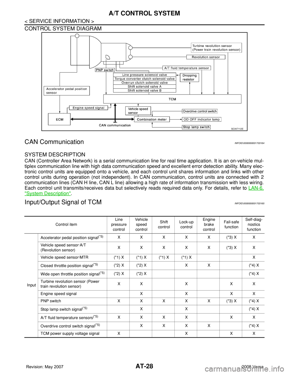
CONTROL SYSTEM DIAGRAM
CAN CommunicationINFOID:0000000001703164
SYSTEM DESCRIPTION
CAN (Controller Area Network) is a serial communication line for real time application. It is an on-vehicle mul-
tiplex communication line with high data communication speed and excellent error detection ability. Many elec-
tronic control units are equipped onto a vehicle, and each control unit shares information and links with other
control units during operation (not independent). In CAN communication, control units are connected with 2
communication lines (CAN H line, CAN L line) allowing a high rate of information transmission with less wiring.
Each control unit transmits/receives data but selectively reads required data only. For details, refer to LAN-6,
"System Description".
Input/Output Signal of TCMINFOID:0000000001703165
SCIA7112E
Control itemLine
pressure
controlVehicle
speed
controlShift
controlLock-up
controlEngine
brake
controlFail-safe
functionSelf-diag-
nostics
function
InputAccelerator pedal position signal
(*5)XXXXX(*3) XX
Vehicle speed sensor·A/T
(Revolution sensor)XXXXX(*3) XX
Vehicle speed sensor·MTR (*1) X (*1) X (*1) X (*1) X X
Closed throttle position signal
(*5)(*2) X (*2) X X X (*4) X
Wide open throttle position signal
(*5)(*2) X (*2) X (*4) X
Turbine revolution sensor (Power
train revolution sensor)XXXXX
Engine speed signal X X X X
PNP switch XXXXX(*3) X(*4) X
Stop lamp switch signal
(*5)XX (*4) X
A/T fluid temperature sensors
(*5)XXXX XX
Overdrive control switch signal
(*5)XXXX (*4) X
TCM power supply voltage signal X X X X
Page 41 of 2771
A/T CONTROL SYSTEM
AT-29
< SERVICE INFORMATION >
D
E
F
G
H
I
J
K
L
MA
B
AT
N
O
P
*1: Spare for vehicle speed sensor·A/T (revolution sensor)
*2: Spare for accelerator pedal position signal
*3: If these input and output signals are different, the TCM triggers the fail-safe function.
*4: Used as a condition for starting self-diagnostics; if self-diagnosis are not started, it is judged that there is some kind of error.
*5: Input by CAN communications.
*6: Output by CAN communications.
Line Pressure ControlINFOID:0000000001703166
• TCM has various line pressure control characteristics to match the driving conditions.
• An ON-OFF duty signal is sent to the line pressure solenoid valve based on TCM characteristics.
• Hydraulic pressure on the clutch and brake is electronically controlled through the line pressure solenoid
valve to accommodate engine torque. This results in smooth shift operation.
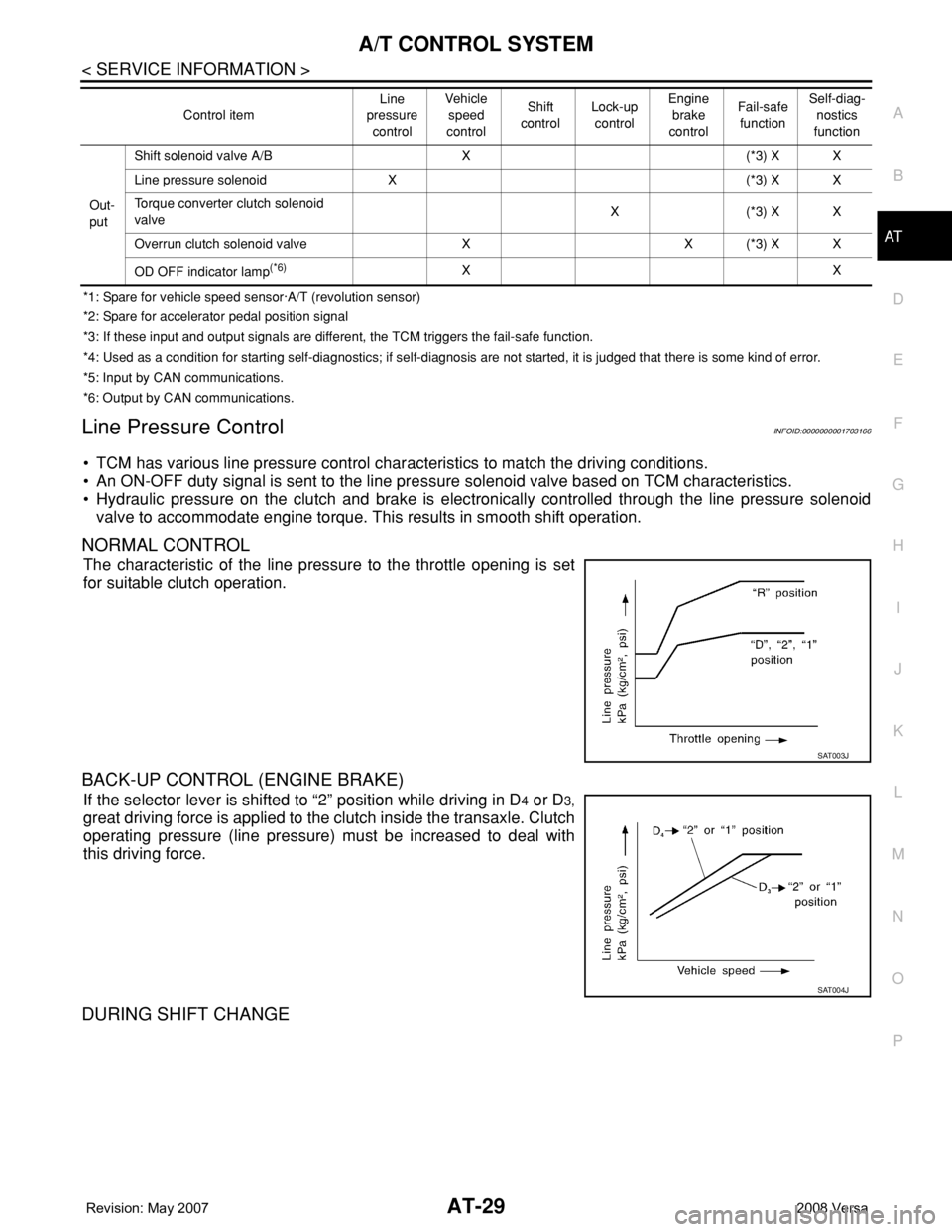
NORMAL CONTROL
The characteristic of the line pressure to the throttle opening is set
for suitable clutch operation.
BACK-UP CONTROL (ENGINE BRAKE)
If the selector lever is shifted to “2” position while driving in D4 or D3,
great driving force is applied to the clutch inside the transaxle. Clutch
operating pressure (line pressure) must be increased to deal with
this driving force.
DURING SHIFT CHANGE
Out-
putShift solenoid valve A/B X (*3) X X
Line pressure solenoid X (*3) X X
Torque converter clutch solenoid
valveX(*3) XX
Overrun clutch solenoid valve X X (*3) X X
OD OFF indicator lamp
(*6)XX Control itemLine
pressure
controlVeh icl e
speed
controlShift
controlLock-up
controlEngine
brake
controlFail-safe
functionSelf-diag-
nostics
function
SAT003J
SAT004J
Page 46 of 2771

AT-34
< SERVICE INFORMATION >
A/T CONTROL SYSTEM
Control Valve
INFOID:0000000001703170
FUNCTION OF CONTROL VALVES
Centrifugal Cancel MechanismINFOID:0000000001703171
FUNCTION
The centrifugal cancel mechanism is a mechanism to cancel the centrifugal hydraulic pressure instead of the
conventional check balls. It cancels the centrifugal hydraulic pressure which is generated as high clutch drum
rotates, and it allows for preventing high clutch from dragging and for providing stable high clutch piston press-
ing force in all revolution speeds.
STRUCTURE/OPERATION
Valve name Function
Pressure regulator valve, plug and sleeve
plugRegulates oil discharged from the oil pump to provide optimum line pressure for all driving
conditions.
Pressure modifier valve and sleeve Used as a signal supplementary valve to the pressure regulator valve. Regulates pres-
sure-modifier pressure (signal pressure) which controls optimum line pressure for all driv-
ing conditions.
Pilot valve Regulates line pressure to maintain a constant pilot pressure level which controls lock-up
mechanism, overrun clutch, shift timing.
Accumulator control valve Regulates accumulator back-pressure to pressure suited to driving conditions.
Manual valve Directs line pressure to oil circuits corresponding to select positions.
Hydraulic pressure drains when the shift lever is in Neutral.
Shift valve A Simultaneously switches three oil circuits using output pressure of shift solenoid valve A
to meet driving conditions (vehicle speed, throttle opening, etc.).
Provides automatic downshifting and upshifting (1st → 2nd → 3rd → 4th gears/4th → 3rd
→ 2nd → 1st gears) in combination with shift valve B.
Shift valve B Simultaneously switches two oil circuits using output pressure of shift solenoid valve B in
relation to driving conditions (vehicle speed, throttle opening, etc.).
Provides automatic downshifting and upshifting (1st → 2nd → 3rd → 4th gears/4th → 3rd
→ 2nd → 1st gears) in combination with shift valve A.
Overrun clutch control valve Switches hydraulic circuits to prevent engagement of the overrun clutch simultaneously
with application of the brake band in D
4. (Interlocking occurs if the overrun clutch engages
during D
4.)
1st reducing valve Reduces low & reverse brake pressure to dampen engine-brake shock when downshift-
ing from the 1st position 1
2 to 11.
Overrun clutch reducing valve Reduces oil pressure directed to the overrun clutch and prevents engine-brake shock.
In the 1st and 2nd positions, line pressure acts on the overrun clutch reducing valve to
increase the pressure-regulating point, with resultant engine brake capability.
Torque converter relief valve Prevents an excessive rise in torque converter pressure.
Torque converter clutch control valve, plug
and sleeveActivates or inactivates the lock-up function.
Also provides smooth lock-up through transient application and release of the lock-up
system.
1-2 accumulator valve and piston Lessens the shock find when the 2nd gear band servo contracts, and provides smooth
shifting.
3-2 timing valve Switches the pace that oil pressure is released depending on vehicle speed; maximizes
the high clutch release timing, and allows for soft downshifting.
Shuttle valve Determines if the overrun clutch solenoid valve should control the 3-2 timing valve or the
overrun clutch control valve and switches between the two.
Cooler check valve At low speeds and with a small load when a little heat is generated, saves the volume of
cooler flow, and stores the oil pressure for lock-up.