NISSAN TIIDA 2008 Service Repair Manual
Manufacturer: NISSAN, Model Year: 2008, Model line: TIIDA, Model: NISSAN TIIDA 2008Pages: 2771, PDF Size: 60.61 MB
Page 551 of 2771
INTELLIGENT KEY SYSTEM
BL-117
< SERVICE INFORMATION >
C
D
E
F
G
H
J
K
L
MA
B
BL
N
O
P
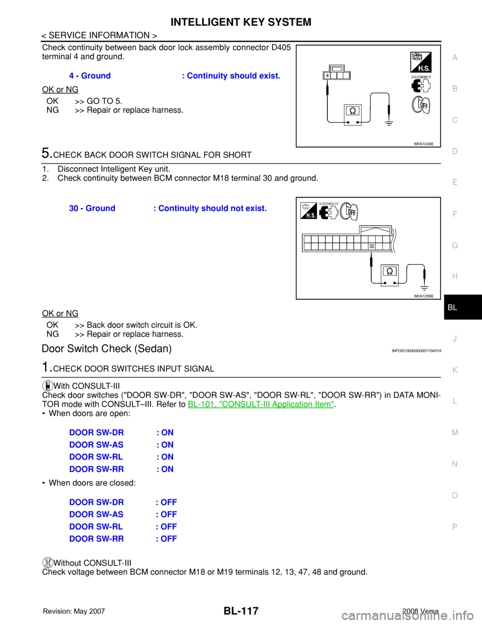
Check continuity between back door lock assembly connector D405
terminal 4 and ground.
OK or NG
OK >> GO TO 5.
NG >> Repair or replace harness.
5.CHECK BACK DOOR SWITCH SIGNAL FOR SHORT
1. Disconnect Intelligent Key unit.
2. Check continuity between BCM connector M18 terminal 30 and ground.
OK or NG
OK >> Back door switch circuit is OK.
NG >> Repair or replace harness.
Door Switch Check (Sedan)INFOID:0000000001704019
1.CHECK DOOR SWITCHES INPUT SIGNAL
With CONSULT-III
Check door switches ("DOOR SW-DR", "DOOR SW-AS", "DOOR SW-RL", "DOOR SW-RR") in DATA MONI-
TOR mode with CONSULT–III. Refer to BL-101, "
CONSULT-III Application Item".
• When doors are open:
• When doors are closed:
Without CONSULT-III
Check voltage between BCM connector M18 or M19 terminals 12, 13, 47, 48 and ground.4 - Ground : Continuity should exist.
WIIA1246E
30 - Ground : Continuity should not exist.
WIIA1299E
DOOR SW-DR : ON
DOOR SW-AS : ON
DOOR SW-RL : ON
DOOR SW-RR : ON
DOOR SW-DR : OFF
DOOR SW-AS : OFF
DOOR SW-RL : OFF
DOOR SW-RR : OFF
Page 552 of 2771
BL-118
< SERVICE INFORMATION >
INTELLIGENT KEY SYSTEM
OK or NG
OK >> Door switch circuit is OK.
NG >> GO TO 2.
2.CHECK DOOR SWITCH CIRCUIT
1. Turn ignition switch OFF.
2. Disconnect door switch and BCM.
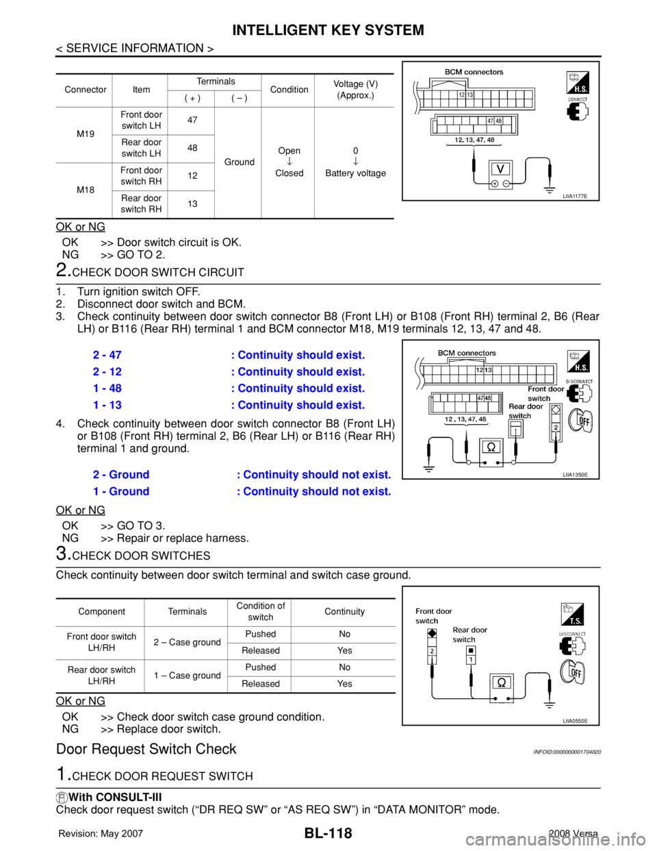
3. Check continuity between door switch connector B8 (Front LH) or B108 (Front RH) terminal 2, B6 (Rear
LH) or B116 (Rear RH) terminal 1 and BCM connector M18, M19 terminals 12, 13, 47 and 48.
4. Check continuity between door switch connector B8 (Front LH)
or B108 (Front RH) terminal 2, B6 (Rear LH) or B116 (Rear RH)
terminal 1 and ground.
OK or NG
OK >> GO TO 3.
NG >> Repair or replace harness.
3.CHECK DOOR SWITCHES
Check continuity between door switch terminal and switch case ground.
OK or NG
OK >> Check door switch case ground condition.
NG >> Replace door switch.
Door Request Switch CheckINFOID:0000000001704020
1.CHECK DOOR REQUEST SWITCH
With CONSULT-III
Check door request switch (“DR REQ SW” or “AS REQ SW”) in “DATA MONITOR” mode.
Connector ItemTe r m i n a l s
ConditionVoltage (V)
(Approx.)
( + ) ( – )
M19Front door
switch LH47
GroundOpen
↓
Closed0
↓
Battery voltage Rear door
switch LH48
M18Front door
switch RH12
Rear door
switch RH13
LIIA1177E
2 - 47 : Continuity should exist.
2 - 12 : Continuity should exist.
1 - 48 : Continuity should exist.
1 - 13 : Continuity should exist.
2 - Ground : Continuity should not exist.
1 - Ground : Continuity should not exist.
LIIA1350E
Component TerminalsCondition of
switchContinuity
Front door switch
LH/RH2 – Case groundPushed No
Released Yes
Rear door switch
LH/RH1 – Case groundPushed No
Released Yes
LIIA0550E
Page 553 of 2771
INTELLIGENT KEY SYSTEM
BL-119
< SERVICE INFORMATION >
C
D
E
F
G
H
J
K
L
MA
B
BL
N
O
P
Without CONSULT-III
1. Turn ignition switch OFF.
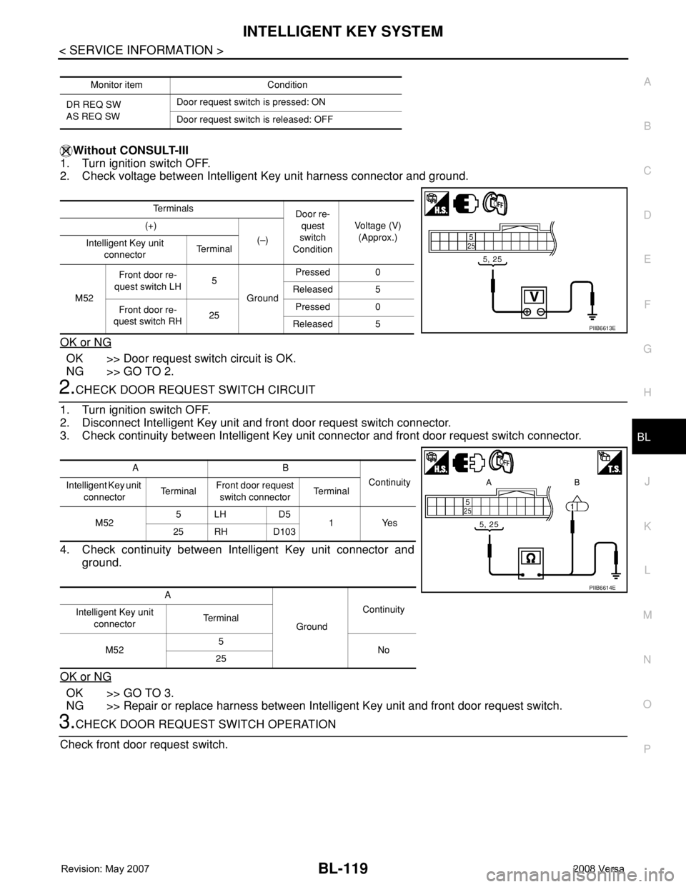
2. Check voltage between Intelligent Key unit harness connector and ground.
OK or NG
OK >> Door request switch circuit is OK.
NG >> GO TO 2.
2.CHECK DOOR REQUEST SWITCH CIRCUIT
1. Turn ignition switch OFF.
2. Disconnect Intelligent Key unit and front door request switch connector.
3. Check continuity between Intelligent Key unit connector and front door request switch connector.
4. Check continuity between Intelligent Key unit connector and
ground.
OK or NG
OK >> GO TO 3.
NG >> Repair or replace harness between Intelligent Key unit and front door request switch.
3.CHECK DOOR REQUEST SWITCH OPERATION
Check front door request switch.
Monitor item Condition
DR REQ SW
AS REQ SWDoor request switch is pressed: ON
Door request switch is released: OFF
Te r m i n a l s
Door re-
quest
switch
ConditionVoltage (V)
(Approx.) (+)
(–)
Intelligent Key unit
connectorTe r m i n a l
M52Front door re-
quest switch LH5
GroundPressed 0
Released 5
Front door re-
quest switch RH25Pressed 0
Released 5
PIIB6613E
AB
Continuity
Intelligent Key unit
connectorTe r m i n a lFront door request
switch connectorTe r m i n a l
M525LH D5
1Yes
25 RH D103
A
GroundContinuity
Intelligent Key unit
connectorTe r m i n a l
M525
No
25
PIIB6614E
Page 554 of 2771
BL-120
< SERVICE INFORMATION >
INTELLIGENT KEY SYSTEM
OK or NG
OK >> GO TO 4.
NG >> Replace front door request switch.
4.CHECK DOOR REQUEST SWITCH GROUND CIRCUIT
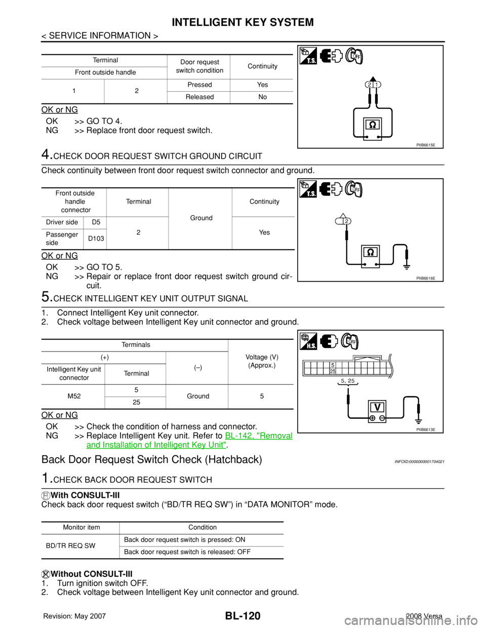
Check continuity between front door request switch connector and ground.
OK or NG
OK >> GO TO 5.
NG >> Repair or replace front door request switch ground cir-
cuit.
5.CHECK INTELLIGENT KEY UNIT OUTPUT SIGNAL
1. Connect Intelligent Key unit connector.
2. Check voltage between Intelligent Key unit connector and ground.
OK or NG
OK >> Check the condition of harness and connector.
NG >> Replace Intelligent Key unit. Refer to BL-142, "
Removal
and Installation of Intelligent Key Unit".
Back Door Request Switch Check (Hatchback)INFOID:0000000001704021
1.CHECK BACK DOOR REQUEST SWITCH
With CONSULT-III
Check back door request switch (“BD/TR REQ SW”) in “DATA MONITOR” mode.
Without CONSULT-III
1. Turn ignition switch OFF.
2. Check voltage between Intelligent Key unit connector and ground.
Te r m i n a l
Door request
switch conditionContinuity
Front outside handle
12Pressed Yes
Released No
PIIB6615E
Front outside
handle
connectorTe r m i n a l
GroundContinuity
Driver side D5
2Yes
Passenger
sideD103
PIIB6616E
Te r m i n a l s
Voltage (V)
(Approx.) (+)
(–)
Intelligent Key unit
connectorTe r m i n a l
M525
Ground 5
25
PIIB6613E
Monitor item Condition
BD/TR REQ SWBack door request switch is pressed: ON
Back door request switch is released: OFF
Page 555 of 2771
INTELLIGENT KEY SYSTEM
BL-121
< SERVICE INFORMATION >
C
D
E
F
G
H
J
K
L
MA
B
BL
N
O
P
OK or NG
OK >> Back door request switch circuit is OK.
NG >> GO TO 2.
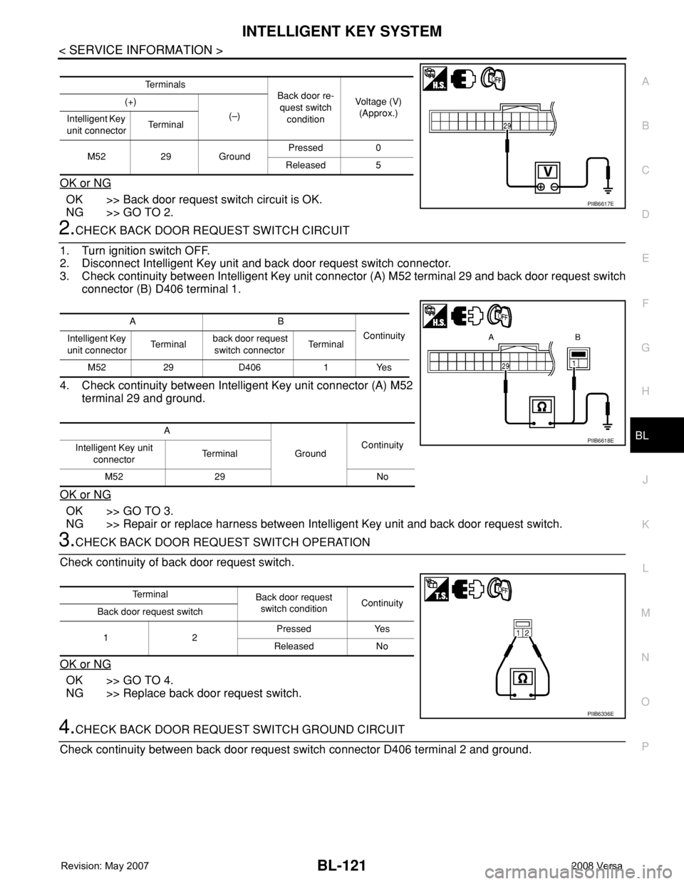
2.CHECK BACK DOOR REQUEST SWITCH CIRCUIT
1. Turn ignition switch OFF.
2. Disconnect Intelligent Key unit and back door request switch connector.
3. Check continuity between Intelligent Key unit connector (A) M52 terminal 29 and back door request switch
connector (B) D406 terminal 1.
4. Check continuity between Intelligent Key unit connector (A) M52
terminal 29 and ground.
OK or NG
OK >> GO TO 3.
NG >> Repair or replace harness between Intelligent Key unit and back door request switch.
3.CHECK BACK DOOR REQUEST SWITCH OPERATION
Check continuity of back door request switch.
OK or NG
OK >> GO TO 4.
NG >> Replace back door request switch.
4.CHECK BACK DOOR REQUEST SWITCH GROUND CIRCUIT
Check continuity between back door request switch connector D406 terminal 2 and ground.
Te r m i n a l s
Back door re-
quest switch
conditionVoltage (V)
(Approx.) (+)
(–)
Intelligent Key
unit connectorTe r m i n a l
M52 29 GroundPressed 0
Released 5
PIIB6617E
AB
Continuity
Intelligent Key
unit connectorTe r m i n a l back door request
switch connectorTe r m i n a l
M52 29 D406 1 Yes
A
GroundContinuity
Intelligent Key unit
connectorTe r m i n a l
M52 29 No
PIIB6618E
Te r m i n a l
Back door request
switch conditionContinuity
Back door request switch
12Pressed Yes
Released No
PIIB6336E
Page 556 of 2771
BL-122
< SERVICE INFORMATION >
INTELLIGENT KEY SYSTEM
OK or NG
OK >> GO TO 5.
NG >> Repair or replace back door request switch ground cir-
cuit.
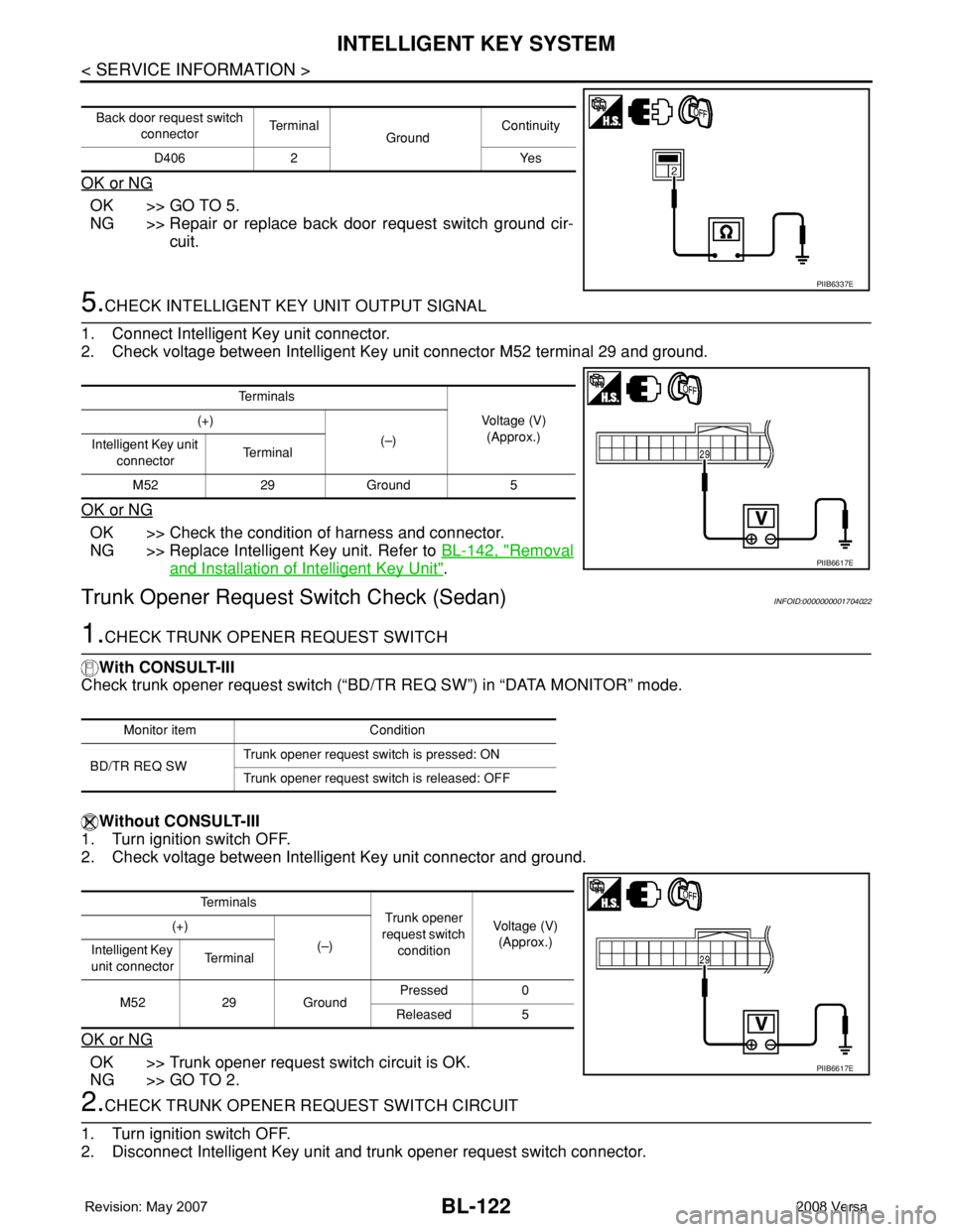
5.CHECK INTELLIGENT KEY UNIT OUTPUT SIGNAL
1. Connect Intelligent Key unit connector.
2. Check voltage between Intelligent Key unit connector M52 terminal 29 and ground.
OK or NG
OK >> Check the condition of harness and connector.
NG >> Replace Intelligent Key unit. Refer to BL-142, "
Removal
and Installation of Intelligent Key Unit".
Trunk Opener Request Switch Check (Sedan)INFOID:0000000001704022
1.CHECK TRUNK OPENER REQUEST SWITCH
With CONSULT-III
Check trunk opener request switch (“BD/TR REQ SW”) in “DATA MONITOR” mode.
Without CONSULT-III
1. Turn ignition switch OFF.
2. Check voltage between Intelligent Key unit connector and ground.
OK or NG
OK >> Trunk opener request switch circuit is OK.
NG >> GO TO 2.
2.CHECK TRUNK OPENER REQUEST SWITCH CIRCUIT
1. Turn ignition switch OFF.
2. Disconnect Intelligent Key unit and trunk opener request switch connector.
Back door request switch
connectorTe r m i n a l
GroundContinuity
D406 2 Yes
PIIB6337E
Te r m i n a l s
Voltage (V)
(Approx.) (+)
(–)
Intelligent Key unit
connectorTe r m i n a l
M52 29 Ground 5
PIIB6617E
Monitor item Condition
BD/TR REQ SWTrunk opener request switch is pressed: ON
Trunk opener request switch is released: OFF
Te r m i n a l s
Trunk opener
request switch
conditionVoltage (V)
(Approx.) (+)
(–)
Intelligent Key
unit connectorTe r m i n a l
M52 29 GroundPressed 0
Released 5
PIIB6617E
Page 557 of 2771
INTELLIGENT KEY SYSTEM
BL-123
< SERVICE INFORMATION >
C
D
E
F
G
H
J
K
L
MA
B
BL
N
O
P
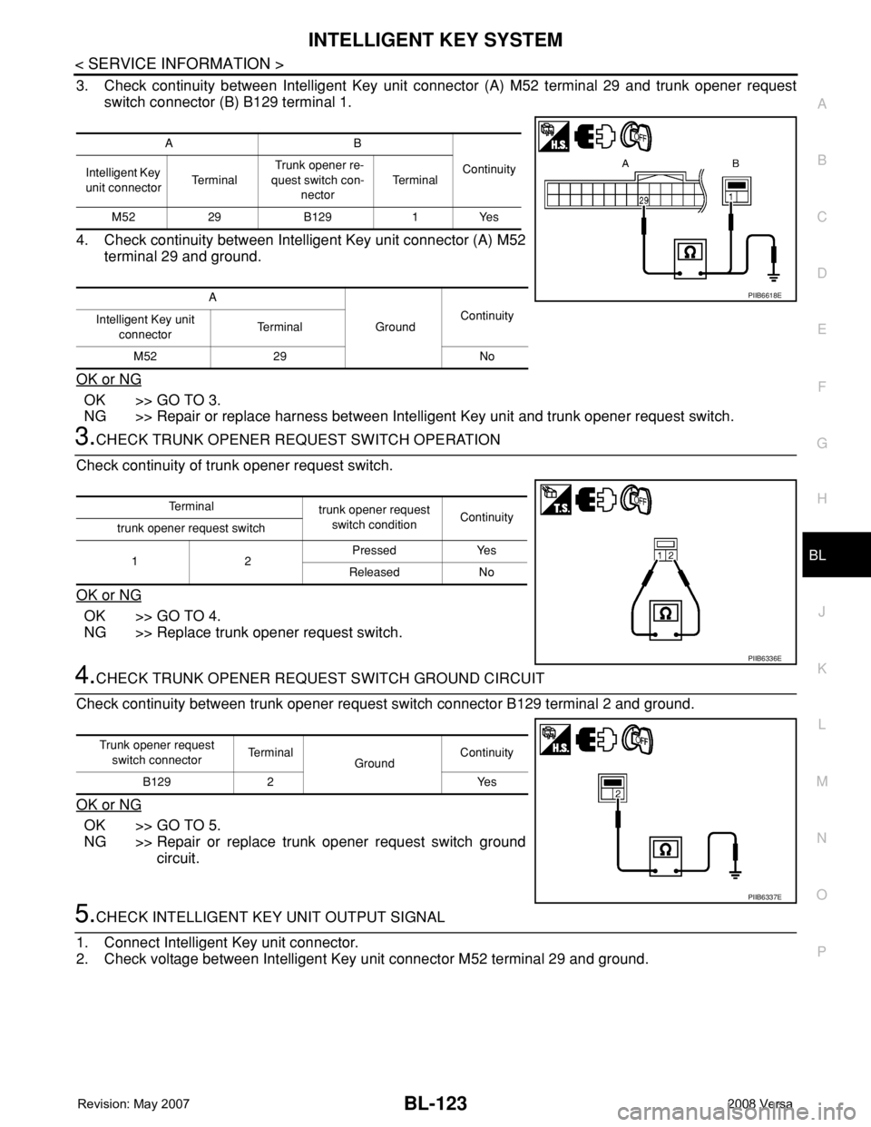
3. Check continuity between Intelligent Key unit connector (A) M52 terminal 29 and trunk opener request
switch connector (B) B129 terminal 1.
4. Check continuity between Intelligent Key unit connector (A) M52
terminal 29 and ground.
OK or NG
OK >> GO TO 3.
NG >> Repair or replace harness between Intelligent Key unit and trunk opener request switch.
3.CHECK TRUNK OPENER REQUEST SWITCH OPERATION
Check continuity of trunk opener request switch.
OK or NG
OK >> GO TO 4.
NG >> Replace trunk opener request switch.
4.CHECK TRUNK OPENER REQUEST SWITCH GROUND CIRCUIT
Check continuity between trunk opener request switch connector B129 terminal 2 and ground.
OK or NG
OK >> GO TO 5.
NG >> Repair or replace trunk opener request switch ground
circuit.
5.CHECK INTELLIGENT KEY UNIT OUTPUT SIGNAL
1. Connect Intelligent Key unit connector.
2. Check voltage between Intelligent Key unit connector M52 terminal 29 and ground.
AB
Continuity
Intelligent Key
unit connectorTe r m i n a l Trunk opener re-
quest switch con-
nectorTe r m i n a l
M52 29 B129 1 Yes
A
GroundContinuity
Intelligent Key unit
connectorTe r m i n a l
M52 29 No
PIIB6618E
Te r m i n a l
trunk opener request
switch conditionContinuity
trunk opener request switch
12Pressed Yes
Released No
PIIB6336E
Trunk opener request
switch connectorTe r m i n a l
GroundContinuity
B129 2 Yes
PIIB6337E
Page 558 of 2771
BL-124
< SERVICE INFORMATION >
INTELLIGENT KEY SYSTEM
OK or NG
OK >> Check the condition of harness and connector.
NG >> Replace Intelligent Key unit. Refer to BL-142, "
Removal
and Installation of Intelligent Key Unit".
Unlock Sensor CheckINFOID:0000000001704023
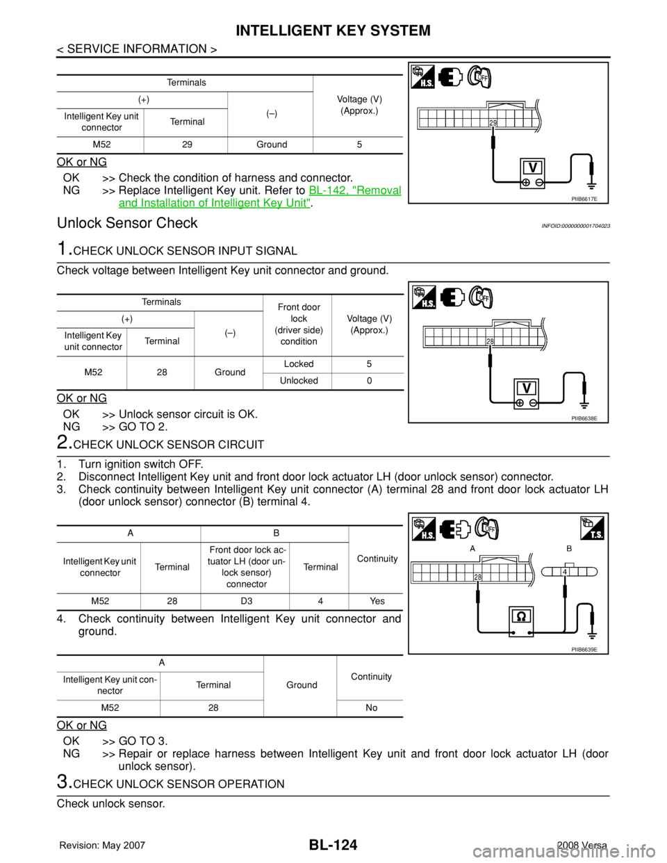
1.CHECK UNLOCK SENSOR INPUT SIGNAL
Check voltage between Intelligent Key unit connector and ground.
OK or NG
OK >> Unlock sensor circuit is OK.
NG >> GO TO 2.
2.CHECK UNLOCK SENSOR CIRCUIT
1. Turn ignition switch OFF.
2. Disconnect Intelligent Key unit and front door lock actuator LH (door unlock sensor) connector.
3. Check continuity between Intelligent Key unit connector (A) terminal 28 and front door lock actuator LH
(door unlock sensor) connector (B) terminal 4.
4. Check continuity between Intelligent Key unit connector and
ground.
OK or NG
OK >> GO TO 3.
NG >> Repair or replace harness between Intelligent Key unit and front door lock actuator LH (door
unlock sensor).
3.CHECK UNLOCK SENSOR OPERATION
Check unlock sensor.
Te r m i n a l s
Voltage (V)
(Approx.) (+)
(–)
Intelligent Key unit
connectorTe r m i n a l
M52 29 Ground 5
PIIB6617E
Te r m i n a l s
Front door
lock
(driver side)
conditionVoltage (V)
(Approx.) (+)
(–)
Intelligent Key
unit connectorTe r m i n a l
M52 28 GroundLocked 5
Unlocked 0
PIIB6638E
AB
Continuity
Intelligent Key unit
connectorTe r m i n a l Front door lock ac-
tuator LH (door un-
lock sensor)
connectorTe r m i n a l
M52 28 D3 4 Yes
A
GroundContinuity
Intelligent Key unit con-
nectorTerminal
M52 28 No
PIIB6639E
Page 559 of 2771
INTELLIGENT KEY SYSTEM
BL-125
< SERVICE INFORMATION >
C
D
E
F
G
H
J
K
L
MA
B
BL
N
O
P
OK or NG
OK >> GO TO 4.
NG >> Replace unlock sensor.
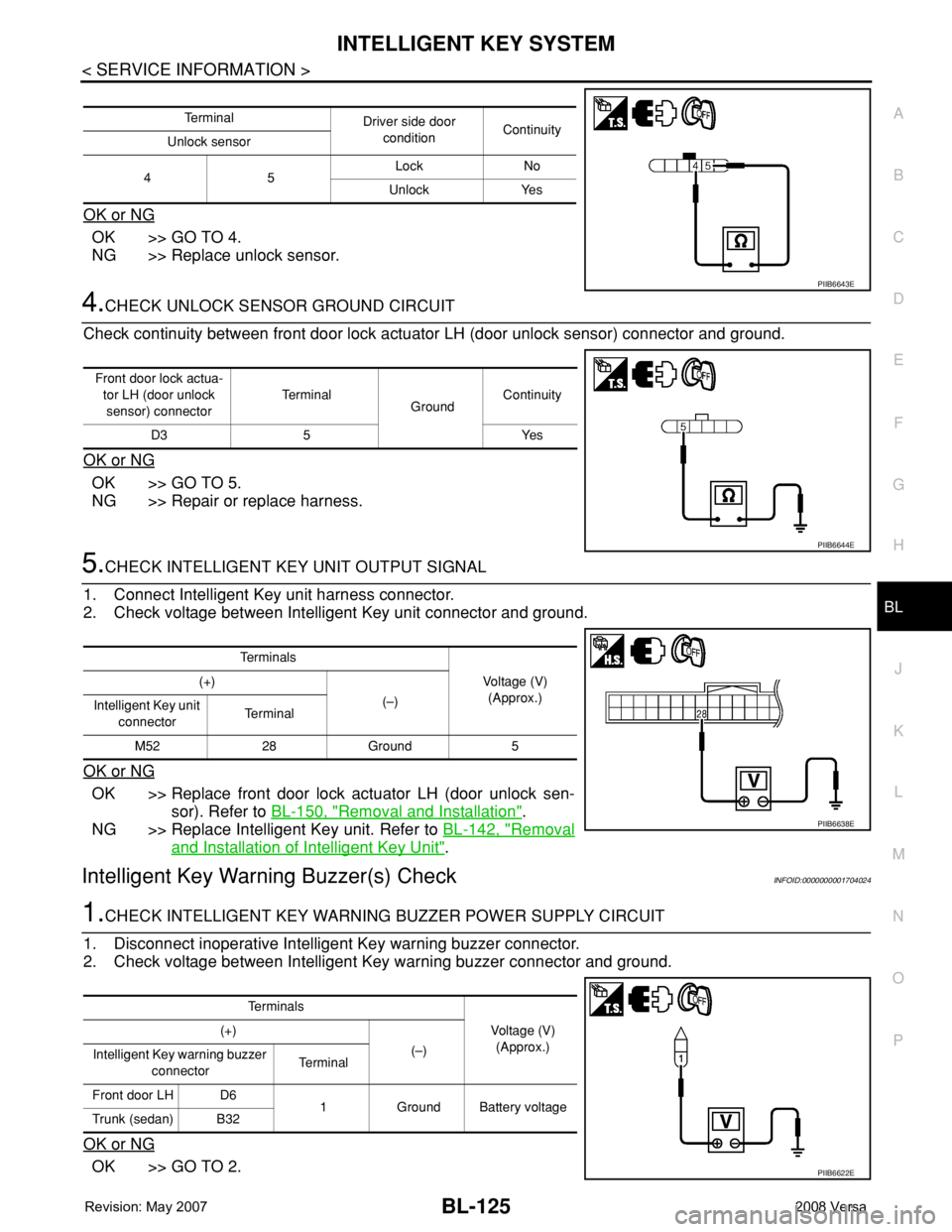
4.CHECK UNLOCK SENSOR GROUND CIRCUIT
Check continuity between front door lock actuator LH (door unlock sensor) connector and ground.
OK or NG
OK >> GO TO 5.
NG >> Repair or replace harness.
5.CHECK INTELLIGENT KEY UNIT OUTPUT SIGNAL
1. Connect Intelligent Key unit harness connector.
2. Check voltage between Intelligent Key unit connector and ground.
OK or NG
OK >> Replace front door lock actuator LH (door unlock sen-
sor). Refer to BL-150, "
Removal and Installation".
NG >> Replace Intelligent Key unit. Refer to BL-142, "
Removal
and Installation of Intelligent Key Unit".
Intelligent Key Warning Buzzer(s) CheckINFOID:0000000001704024
1.CHECK INTELLIGENT KEY WARNING BUZZER POWER SUPPLY CIRCUIT
1. Disconnect inoperative Intelligent Key warning buzzer connector.
2. Check voltage between Intelligent Key warning buzzer connector and ground.
OK or NG
OK >> GO TO 2.
Te r m i n a l
Driver side door
conditionContinuity
Unlock sensor
45Lock No
Unlock Yes
PIIB6643E
Front door lock actua-
tor LH (door unlock
sensor) connectorTe r m i n a l
GroundContinuity
D3 5 Yes
PIIB6644E
Te r m i n a l s
Voltage (V)
(Approx.) (+)
(–)
Intelligent Key unit
connectorTe r m i n a l
M52 28 Ground 5
PIIB6638E
Te r m i n a l s
Voltage (V)
(Approx.) (+)
(–)
Intelligent Key warning buzzer
connectorTerminal
Front door LH D6
1 Ground Battery voltage
Trunk (sedan) B32
PIIB6622E
Page 560 of 2771
BL-126
< SERVICE INFORMATION >
INTELLIGENT KEY SYSTEM
NG >> Repair or replace Intelligent Key warning buzzer power supply circuit.
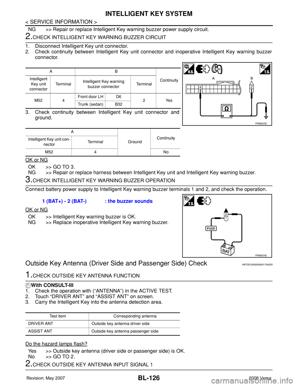
2.CHECK INTELLIGENT KEY WARNING BUZZER CIRCUIT
1. Disconnect Intelligent Key unit connector.
2. Check continuity between Intelligent Key unit connector and inoperative Intelligent Key warning buzzer
connector.
3. Check continuity between Intelligent Key unit connector and
ground.
OK or NG
OK >> GO TO 3.
NG >> Repair or replace harness between Intelligent Key unit and Intelligent Key warning buzzer.
3.CHECK INTELLIGENT KEY WARNING BUZZER OPERATION
Connect battery power supply to Intelligent Key warning buzzer terminals 1 and 2, and check the operation.
OK or NG
OK >> Intelligent Key warning buzzer is OK.
NG >> Replace inoperative Intelligent Key warning buzzer.
Outside Key Antenna (Driver Side and Passenger Side) CheckINFOID:0000000001704025
1.CHECK OUTSIDE KEY ANTENNA FUNCTION
With CONSULT-III
1. Check the operation with (“ANTENNA”) in the ACTIVE TEST.
2. Touch “DRIVER ANT” and “ASSIST ANT” on screen.
3. Carry the Intelligent Key into the antenna detection area.
Do the hazard lamps flash?
Yes >> Outside key antenna (driver side or passenger side) is OK.
No >> GO TO 2.
2.CHECK OUTSIDE KEY ANTENNA INPUT SIGNAL 1
AB
Continuity Intelligent
Key unit
connectorTe r m i n a lIntelligent Key warning
buzzer connectorTe r m i n a l
M52 4Front door LH D6
2Yes
Trunk (sedan) B32
A
GroundContinuity
Intelligent Key unit con-
nectorTerminal
M52 4 No
PIIB6623E
1 (BAT+) - 2 (BAT-) : the buzzer sounds
PIIB6624E
Test item Corresponding antenna
DRIVER ANT Outside key antenna driver side
ASSIST ANT Outside key antenna passenger side