NISSAN TIIDA 2008 Service Repair Manual
Manufacturer: NISSAN, Model Year: 2008, Model line: TIIDA, Model: NISSAN TIIDA 2008Pages: 2771, PDF Size: 60.61 MB
Page 571 of 2771
INTELLIGENT KEY SYSTEM
BL-137
< SERVICE INFORMATION >
C
D
E
F
G
H
J
K
L
MA
B
BL
N
O
P
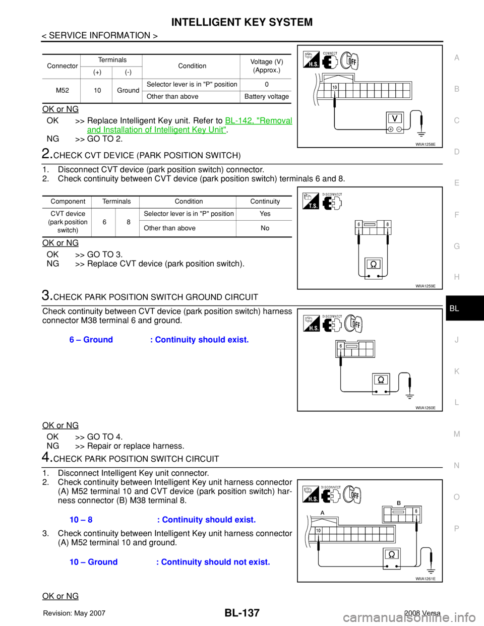
OK or NG
OK >> Replace Intelligent Key unit. Refer to BL-142, "Removal
and Installation of Intelligent Key Unit".
NG >> GO TO 2.
2.CHECK CVT DEVICE (PARK POSITION SWITCH)
1. Disconnect CVT device (park position switch) connector.
2. Check continuity between CVT device (park position switch) terminals 6 and 8.
OK or NG
OK >> GO TO 3.
NG >> Replace CVT device (park position switch).
3.CHECK PARK POSITION SWITCH GROUND CIRCUIT
Check continuity between CVT device (park position switch) harness
connector M38 terminal 6 and ground.
OK or NG
OK >> GO TO 4.
NG >> Repair or replace harness.
4.CHECK PARK POSITION SWITCH CIRCUIT
1. Disconnect Intelligent Key unit connector.
2. Check continuity between Intelligent Key unit harness connector
(A) M52 terminal 10 and CVT device (park position switch) har-
ness connector (B) M38 terminal 8.
3. Check continuity between Intelligent Key unit harness connector
(A) M52 terminal 10 and ground.
OK or NG
ConnectorTe r m i n a l s
ConditionVoltage (V)
(Approx.)
(+) (-)
M52 10 GroundSelector lever is in "P" position 0
Other than above Battery voltage
WIIA1258E
Component Terminals Condition Continuity
CVT device
(park position
switch)68Selector lever is in "P" position Yes
Other than above No
WIIA1259E
6 – Ground : Continuity should exist.
WIIA1260E
10 – 8 : Continuity should exist.
10 – Ground : Continuity should not exist.
WIIA1261E
Page 572 of 2771
BL-138
< SERVICE INFORMATION >
INTELLIGENT KEY SYSTEM
OK >> GO TO 5.
NG >> Repair or replace harness.
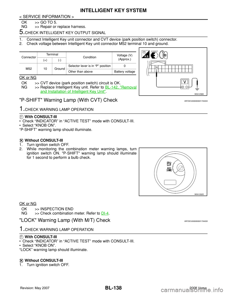
5.CHECK INTELLIGENT KEY OUTPUT SIGNAL
1. Connect Intelligent Key unit connector and CVT device (park position switch) connector.
2. Check voltage between Intelligent Key unit connector M52 terminal 10 and ground.
OK or NG
OK >> CVT device (park position switch) circuit is OK.
NG >> Replace Intelligent Key unit. Refer to BL-142, "
Removal
and Installation of Intelligent Key Unit".
"P-SHIFT" Warning Lamp (With CVT) CheckINFOID:0000000001704034
1.CHECK WARNING LAMP OPERATION
With CONSULT-III
• Check “INDICATOR” in “ACTIVE TEST” mode with CONSULT-III.
• Select “KNOB ON”.
“P-SHIFT” warning lamp should illuminate.
Without CONSULT-III
1. Turn ignition switch OFF.
2. While monitoring the combination meter warning lamps, turn
ignition switch ON. "P-SHIFT" warning lamp should illuminate
for 1 second to perform a bulb check.
OK or NG
OK >> INSPECTION END
NG >> Check combination meter. Refer to DI-4
.
"LOCK" Warning Lamp (With M/T) CheckINFOID:0000000001704035
1.CHECK WARNING LAMP OPERATION
With CONSULT-III
• Check “INDICATOR” in “ACTIVE TEST” mode with CONSULT-III.
• Select “KNOB ON”.
“LOCK” warning lamp should illuminate.
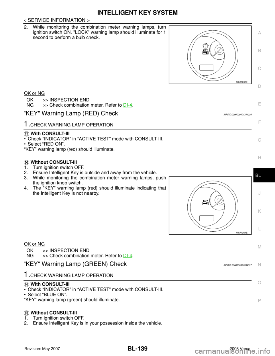
Without CONSULT-III
1. Turn ignition switch OFF.
ConnectorTe r m i n a l
ConditionVoltage (V)
(Approx.)
(+) (-)
M52 10 GroundSelector lever is in “P” position 0
Other than above Battery voltage
WIIA1258E
WIIA1262E
Page 573 of 2771
INTELLIGENT KEY SYSTEM
BL-139
< SERVICE INFORMATION >
C
D
E
F
G
H
J
K
L
MA
B
BL
N
O
P
2. While monitoring the combination meter warning lamps, turn
ignition switch ON. "LOCK" warning lamp should illuminate for 1
second to perform a bulb check.
OK or NG
OK >> INSPECTION END
NG >> Check combination meter. Refer to DI-4
.
"KEY" Warning Lamp (RED) CheckINFOID:0000000001704036
1.CHECK WARNING LAMP OPERATION
With CONSULT-III
• Check “INDICATOR” in “ACTIVE TEST” mode with CONSULT-III.
• Select “RED ON”.
“KEY” warning lamp (red) should illuminate.
Without CONSULT-III
1. Turn ignition switch OFF.
2. Ensure Intelligent Key is outside and away from the vehicle.
3. While monitoring the combination meter warning lamps, push
the ignition knob switch.
4. The "KEY" warning lamp (red) should illuminate indicating that
the Intelligent Key is not nearby.
OK or NG
OK >> INSPECTION END
NG >> Check combination meter. Refer to DI-4
.
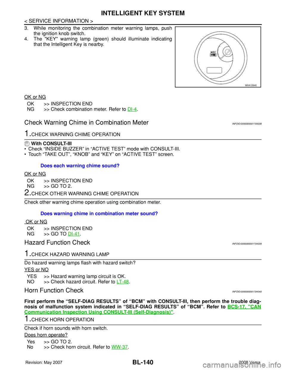
"KEY" Warning Lamp (GREEN) CheckINFOID:0000000001704037
1.CHECK WARNING LAMP OPERATION
With CONSULT-III
• Check “INDICATOR” in “ACTIVE TEST” mode with CONSULT-III.
• Select “BLUE ON”.
“KEY” warning lamp (green) should illuminate.
Without CONSULT-III
1. Turn ignition switch OFF.
2. Ensure Intelligent Key is in your possession inside the vehicle.
WIIA1263E
WIIA1264E
Page 574 of 2771
BL-140
< SERVICE INFORMATION >
INTELLIGENT KEY SYSTEM
3. While monitoring the combination meter warning lamps, push
the ignition knob switch.
4. The "KEY" warning lamp (green) should illuminate indicating
that the Intelligent Key is nearby.
OK or NG
OK >> INSPECTION END
NG >> Check combination meter. Refer to DI-4
.
Check Warning Chime in Combination MeterINFOID:0000000001704038
1.CHECK WARNING CHIME OPERATION
With CONSULT-III
• Check “INSIDE BUZZER” in “ACTIVE TEST” mode with CONSULT-III.
• Touch “TAKE OUT”, “KNOB” and “KEY” on “ACTIVE TEST” screen.
OK or NG
OK >> INSPECTION END
NG >> GO TO 2.
2.CHECK OTHER WARNING CHIME OPERATION
Check other warning chime operation using combination meter.
OK or NG
OK >> INSPECTION END
NG >> GO TO DI-41
.
Hazard Function CheckINFOID:0000000001704039
1.CHECK HAZARD WARNING LAMP
Do hazard warning lamps flash with hazard switch?
YES or NO
YES >> Hazard warning lamp circuit is OK.
NO >> Check hazard circuit. Refer to LT- 4 8
.
Horn Function CheckINFOID:0000000001704040
First perform the “SELF-DIAG RESULTS” of “BCM” with CONSULT-III, then perform the trouble diag-
nosis of malfunction system indicated in “SELF-DIAG RESULTS” of “BCM”. Refer to BCS-17, "
CAN
Communication Inspection Using CONSULT-III (Self-Diagnosis)".
1.CHECK HORN OPERATION
Check if horn sounds with horn switch.
Does horn operate?
Ye s > > G O T O 2 .
No >> Check horn circuit. Refer to WW-37
.
WIIA1264E
Does each warning chime sound?
Does warning chime in combination meter sound?
Page 575 of 2771
INTELLIGENT KEY SYSTEM
BL-141
< SERVICE INFORMATION >
C
D
E
F
G
H
J
K
L
MA
B
BL
N
O
P
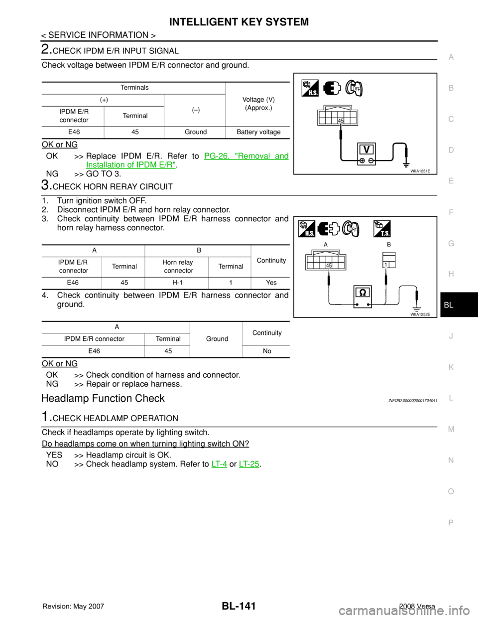
2.CHECK IPDM E/R INPUT SIGNAL
Check voltage between IPDM E/R connector and ground.
OK or NG
OK >> Replace IPDM E/R. Refer to PG-26, "Removal and
Installation of IPDM E/R".
NG >> GO TO 3.
3.CHECK HORN RERAY CIRCUIT
1. Turn ignition switch OFF.
2. Disconnect IPDM E/R and horn relay connector.
3. Check continuity between IPDM E/R harness connector and
horn relay harness connector.
4. Check continuity between IPDM E/R harness connector and
ground.
OK or NG
OK >> Check condition of harness and connector.
NG >> Repair or replace harness.
Headlamp Function CheckINFOID:0000000001704041
1.CHECK HEADLAMP OPERATION
Check if headlamps operate by lighting switch.
Do headlamps come on when turning lighting switch ON?
YES >> Headlamp circuit is OK.
NO >> Check headlamp system. Refer to LT- 4
or LT- 2 5.
Te r m i n a l s
Voltage (V)
(Approx.) (+)
(–)
IPDM E/R
connectorTe r m i n a l
E46 45 Ground Battery voltage
WIIA1251E
AB
Continuity
IPDM E/R
connectorTe r m i n a lHorn relay
connectorTe r m i n a l
E46 45 H-1 1 Yes
A
GroundContinuity
IPDM E/R connector Terminal
E46 45 No
WIIA1252E
Page 576 of 2771
BL-142
< SERVICE INFORMATION >
INTELLIGENT KEY SYSTEM
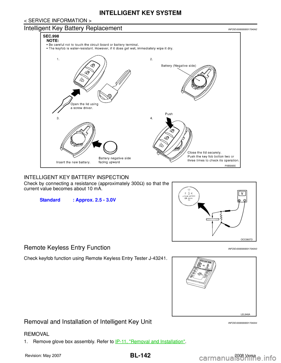
Intelligent Key Battery Replacement
INFOID:0000000001704042
INTELLIGENT KEY BATTERY INSPECTION
Check by connecting a resistance (approximately 300Ω) so that the
current value becomes about 10 mA.
Remote Keyless Entry FunctionINFOID:0000000001704043
Check keyfob function using Remote Keyless Entry Tester J-43241.
Removal and Installation of Intelligent Key UnitINFOID:0000000001704044
REMOVAL
1. Remove glove box assembly. Refer to IP-11, "Removal and Installation".
PIIB5065E
Standard : Approx. 2.5 - 3.0V
OCC0607D
LEL946A
Page 577 of 2771
INTELLIGENT KEY SYSTEM
BL-143
< SERVICE INFORMATION >
C
D
E
F
G
H
J
K
L
MA
B
BL
N
O
P
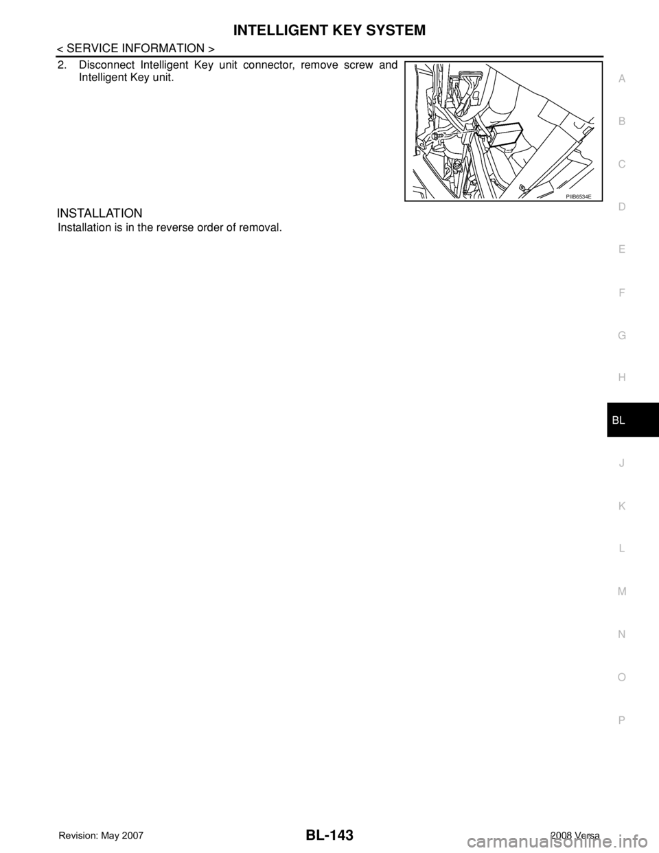
2. Disconnect Intelligent Key unit connector, remove screw and
Intelligent Key unit.
INSTALLATION
Installation is in the reverse order of removal.
PIIB6534E
Page 578 of 2771
BL-144
< SERVICE INFORMATION >
DOOR
DOOR
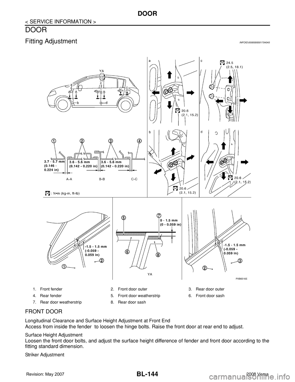
Fitting AdjustmentINFOID:0000000001704045
FRONT DOOR
Longitudinal Clearance and Surface Height Adjustment at Front End
Access from inside the fender to loosen the hinge bolts. Raise the front door at rear end to adjust.
Surface Height Adjustment
Loosen the front door bolts, and adjust the surface height difference of fender and front door according to the
fitting standard dimension.
Striker Adjustment
1. Front fender 2. Front door outer 3. Rear door outer
4. Rear fender 5. Front door weatherstrip 6. Front door sash
7. Rear door weatherstrip 8. Rear door sash
PIIB6516E
Page 579 of 2771
DOOR
BL-145
< SERVICE INFORMATION >
C
D
E
F
G
H
J
K
L
MA
B
BL
N
O
P
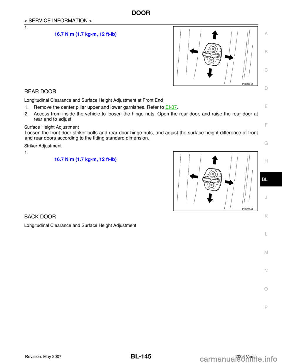
1.
REAR DOOR
Longitudinal Clearance and Surface Height Adjustment at Front End
1. Remove the center pillar upper and lower garnishes. Refer to EI-37.
2. Access from inside the vehicle to loosen the hinge nuts. Open the rear door, and raise the rear door at
rear end to adjust.
Surface Height Adjustment
Loosen the front door striker bolts and rear door hinge nuts, and adjust the surface height difference of front
and rear doors according to the fitting standard dimension.
Striker Adjustment
1.
BACK DOOR
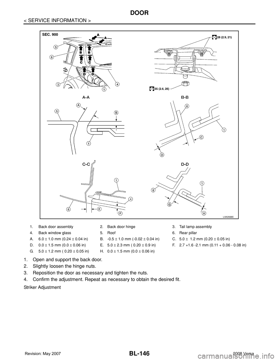
Longitudinal Clearance and Surface Height Adjustment
16.7 N·m (1.7 kg-m, 12 ft-lb)
PIIB2804J
16.7 N·m (1.7 kg-m, 12 ft-lb)
PIIB2804J
Page 580 of 2771
BL-146
< SERVICE INFORMATION >
DOOR
1. Open and support the back door.
2. Slightly loosen the hinge nuts.
3. Reposition the door as necessary and tighten the nuts.
4. Confirm the adjustment. Repeat as necessary to obtain the desired fit.
Striker Adjustment
1. Back door assembly 2. Back door hinge 3. Tail lamp assembly
4. Back window glass 5. Roof 6. Rear pillar
A. 6.0 ± 1.0 mm (0.24 ± 0.04 in) B. -0.5 ± 1.0 mm (-0.02 ± 0.04 in) C. 5.0 ± 1.2 mm (0.20 ± 0.05 in)
D. 0.0 ± 1.5 mm (0.0 ± 0.06 in) E. 5.0 ± 2.3 mm ( 0.20 ± 0.9 in) F. 2.7 +1.6 -2.1 mm (0.11 + 0.06 - 0.08 in)
G. 5.0 ± 1.2 mm ( 0.20 ± 0.05 in) H. 0.0 ± 1.5 mm (0.0 ± 0.06 in)
LIIA2668E