ground NISSAN TIIDA 2008 Service Manual PDF
[x] Cancel search | Manufacturer: NISSAN, Model Year: 2008, Model line: TIIDA, Model: NISSAN TIIDA 2008Pages: 2771, PDF Size: 60.61 MB
Page 363 of 2771
AV-4
< SERVICE INFORMATION >
AUDIO
AUDIO
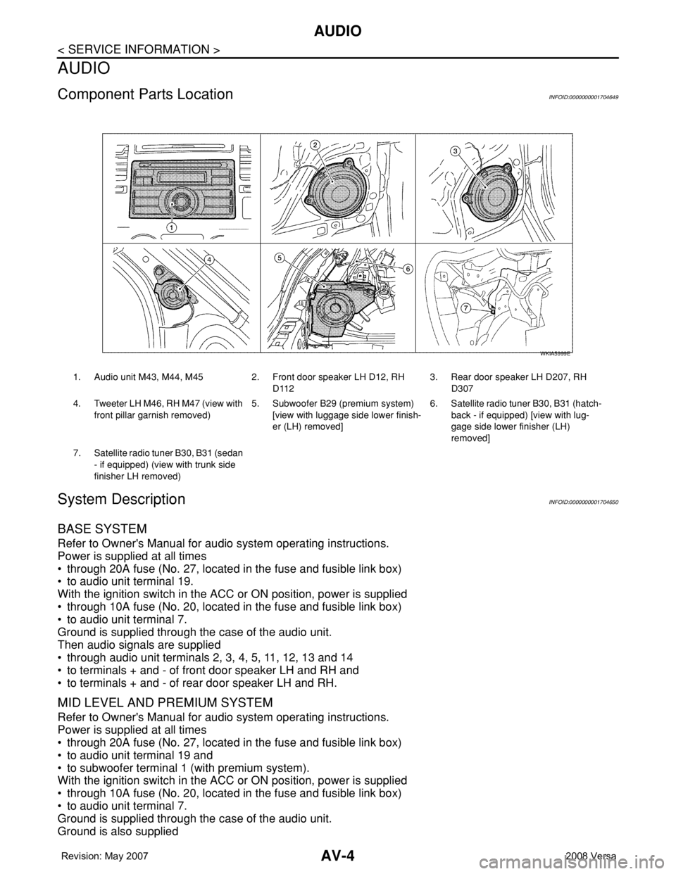
Component Parts LocationINFOID:0000000001704649
System DescriptionINFOID:0000000001704650
BASE SYSTEM
Refer to Owner's Manual for audio system operating instructions.
Power is supplied at all times
• through 20A fuse (No. 27, located in the fuse and fusible link box)
• to audio unit terminal 19.
With the ignition switch in the ACC or ON position, power is supplied
• through 10A fuse (No. 20, located in the fuse and fusible link box)
• to audio unit terminal 7.
Ground is supplied through the case of the audio unit.
Then audio signals are supplied
• through audio unit terminals 2, 3, 4, 5, 11, 12, 13 and 14
• to terminals + and - of front door speaker LH and RH and
• to terminals + and - of rear door speaker LH and RH.
MID LEVEL AND PREMIUM SYSTEM
Refer to Owner's Manual for audio system operating instructions.
Power is supplied at all times
• through 20A fuse (No. 27, located in the fuse and fusible link box)
• to audio unit terminal 19 and
• to subwoofer terminal 1 (with premium system).
With the ignition switch in the ACC or ON position, power is supplied
• through 10A fuse (No. 20, located in the fuse and fusible link box)
• to audio unit terminal 7.
Ground is supplied through the case of the audio unit.
Ground is also supplied
1. Audio unit M43, M44, M45 2. Front door speaker LH D12, RH
D1123. Rear door speaker LH D207, RH
D307
4. Tweeter LH M46, RH M47 (view with
front pillar garnish removed) 5. Subwoofer B29 (premium system)
[view with luggage side lower finish-
er (LH) removed]6. Satellite radio tuner B30, B31 (hatch-
back - if equipped) [view with lug-
gage side lower finisher (LH)
removed]
7. Satellite radio tuner B30, B31 (sedan
- if equipped) (view with trunk side
finisher LH removed)
WKIA5999E
Page 364 of 2771

AUDIO
AV-5
< SERVICE INFORMATION >
C
D
E
F
G
H
I
J
L
MA
B
AV
N
O
P
• to audio unit terminal 21 (with premium system)
• through body grounds M57 and M61 and
• to subwoofer terminal 3 (with premium system)
• through body grounds B7 and B19.
Then audio signals are supplied
• through audio unit terminals 2, 3, 4, 5, 11, 12, 13, and 14
• to terminals + and - of front door speaker LH and RH and
• to terminals + and - of tweeter LH and RH and
• to terminals + and - of rear door speaker LH and RH and
• to terminals 2 and 6 of subwoofer (with premium system).
Steering Wheel Audio Control Switches (with Bluetooth)
When one of steering wheel audio control switches is pushed, the resistance in steering switch circuit changes
depending on which button is pushed.
Satellite Radio Tuner (Pre-wiring)
The satellite radio tuner pre-wiring allows connection of a satellite radio tuner.
Power is supplied at all times
• through 20A fuse (No. 27, located in the fuse and fusible link box)
• to satellite radio tuner pre-wiring terminal 32.
With the ignition switch in the ACC or ON position, power is supplied
• through 10A fuse (No. 20, located in the fuse and fusible link box)
• to satellite radio tuner pre-wiring terminal 36.
Then audio signals are supplied
• through satellite radio tuner pre-wiring terminals 21, 22, 23 and 24
• to audio unit terminals 41, 42, 43 and 44.
Satellite Radio Tuner (Factory Installed)
Power is supplied at all times
• through 20A fuse (No. 27, located in the fuse and fusible link box)
• to satellite radio tuner terminal 32.
With the ignition switch in the ACC or ON position, power is supplied
• through 10A fuse (No. 20, located in the fuse and fusible link box)
• to satellite radio tuner terminal 36.
Ground is supplied through the case of the satellite radio tuner.
Then audio signals are supplied
• through satellite radio tuner terminals 21, 22, 23 and 24
• to audio unit terminals 41, 42, 43 and 44.
Ground is supplied through the case of the satellite radio tuner.
SPEED SENSITIVE VOLUME SYSTEM (MID LEVEL AND PREMIUM SYSTEM)
Volume level of this system goes up and down automatically in proportion to the vehicle speed. The control
level can be selected by the customer. Refer to Owner's Manual for operating instructions.
Page 374 of 2771
AUDIO
AV-15
< SERVICE INFORMATION >
C
D
E
F
G
H
I
J
L
MA
B
AV
N
O
P
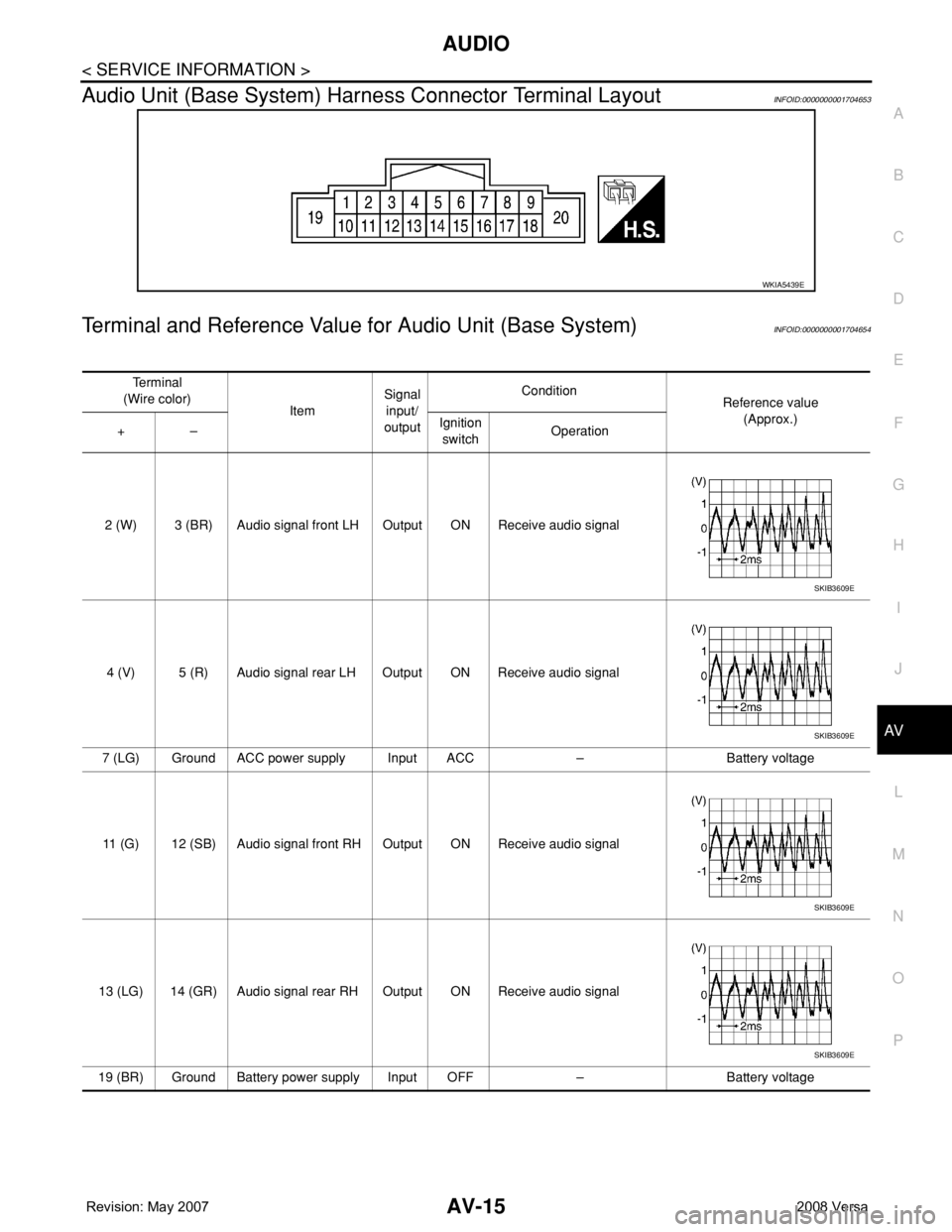
Audio Unit (Base System) Harness Connector Terminal LayoutINFOID:0000000001704653
Terminal and Reference Value for Audio Unit (Base System)INFOID:0000000001704654
WKIA5439E
Te r m i n a l
(Wire color)
ItemSignal
input/
outputCondition
Reference value
(Approx.)
+–Ignition
switchOperation
2 (W) 3 (BR) Audio signal front LH Output ON Receive audio signal
4 (V) 5 (R) Audio signal rear LH Output ON Receive audio signal
7 (LG) Ground ACC power supply Input ACC – Battery voltage
11 (G) 12 (SB) Audio signal front RH Output ON Receive audio signal
13 (LG) 14 (GR) Audio signal rear RH Output ON Receive audio signal
19 (BR) Ground Battery power supply Input OFF – Battery voltage
SKIB3609E
SKIB3609E
SKIB3609E
SKIB3609E
Page 375 of 2771
AV-16
< SERVICE INFORMATION >
AUDIO
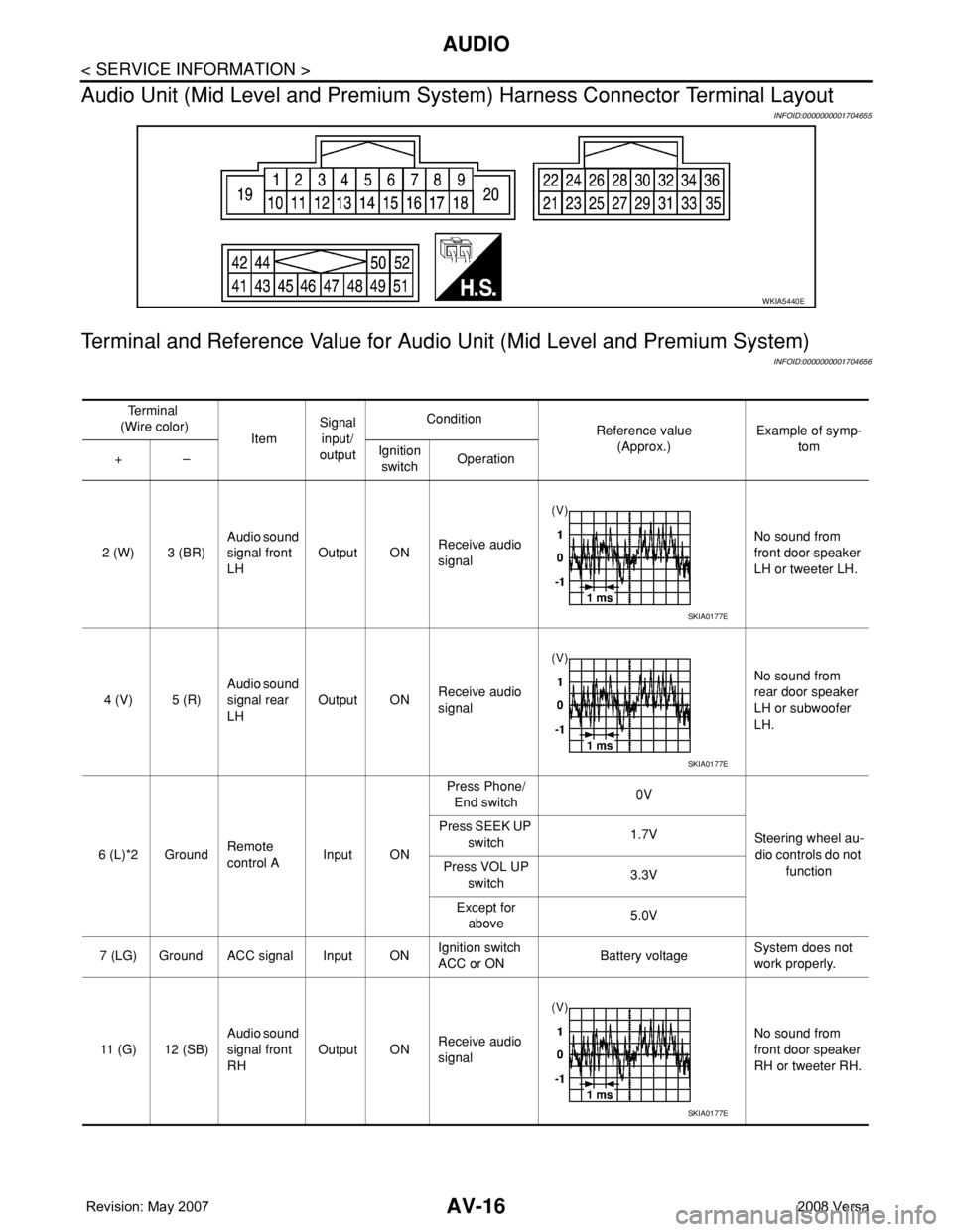
Audio Unit (Mid Level and Premium System) Harness Connector Terminal Layout
INFOID:0000000001704655
Terminal and Reference Value for Audio Unit (Mid Level and Premium System)
INFOID:0000000001704656
WKIA5440E
Te r m i n a l
(Wire color)
ItemSignal
input/
outputCondition
Reference value
(Approx.)Example of symp-
tom
+–Ignition
switchOperation
2 (W) 3 (BR)Audio sound
signal front
LHOutput ONReceive audio
signalNo sound from
front door speaker
LH or tweeter LH.
4 (V) 5 (R)Audio sound
signal rear
LHOutput ONReceive audio
signalNo sound from
rear door speaker
LH or subwoofer
LH.
6 (L)*2 GroundRemote
control AInput ONPress Phone/
End switch0V
Steering wheel au-
dio controls do not
function Press SEEK UP
switch1.7V
Press VOL UP
switch3.3V
Except for
above5.0V
7 (LG) Ground ACC signal Input ONIgnition switch
ACC or ONBattery voltageSystem does not
work properly.
11 (G) 12 (SB)Audio sound
signal front
RHOutput ONReceive audio
signalNo sound from
front door speaker
RH or tweeter RH.
SKIA0177E
SKIA0177E
SKIA0177E
Page 376 of 2771
AUDIO
AV-17
< SERVICE INFORMATION >
C
D
E
F
G
H
I
J
L
MA
B
AV
N
O
P
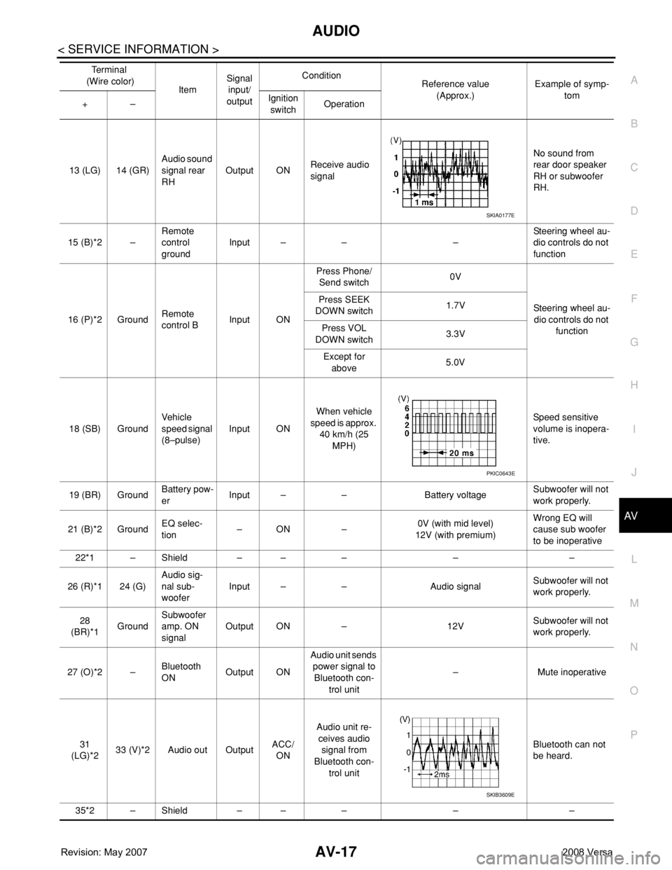
13 (LG) 14 (GR)Audio sound
signal rear
RHOutput ONReceive audio
signalNo sound from
rear door speaker
RH or subwoofer
RH.
15 (B)*2 –Remote
control
groundInput – – –Steering wheel au-
dio controls do not
function
16 (P)*2 GroundRemote
control BInput ONPress Phone/
Send switch0V
Steering wheel au-
dio controls do not
function Press SEEK
DOWN switch1.7V
Press VOL
DOWN switch3.3V
Except for
above5.0V
18 (SB) GroundVehicle
speed signal
(8–pulse)Input ONWhen vehicle
speed is approx.
40 km/h (25
MPH)Speed sensitive
volume is inopera-
tive.
19 (BR) GroundBattery pow-
erInput – – Battery voltageSubwoofer will not
work properly.
21 (B)*2 GroundEQ selec-
tion–ON –0V (with mid level)
12V (with premium)Wrong EQ will
cause sub woofer
to be inoperative
22*1 – Shield – – – – –
26 (R)*1 24 (G)Audio sig-
nal sub-
wooferInput – – Audio signalSubwoofer will not
work properly.
28
(BR)*1GroundSubwoofer
amp. ON
signalOutput ON – 12VSubwoofer will not
work properly.
27 (O)*2 –Bluetooth
ONOutput ONAudio unit sends
power signal to
Bluetooth con-
trol unit– Mute inoperative
31
(LG)*233 (V)*2 Audio out OutputACC/
ONAudio unit re-
ceives audio
signal from
Bluetooth con-
trol unitBluetooth can not
be heard.
35*2 – Shield – – – – –Te r m i n a l
(Wire color)
ItemSignal
input/
outputCondition
Reference value
(Approx.)Example of symp-
tom
+–Ignition
switchOperation
SKIA0177E
PKIC0643E
SKIB3609E
Page 377 of 2771
AV-18
< SERVICE INFORMATION >
AUDIO
*1: With premium system
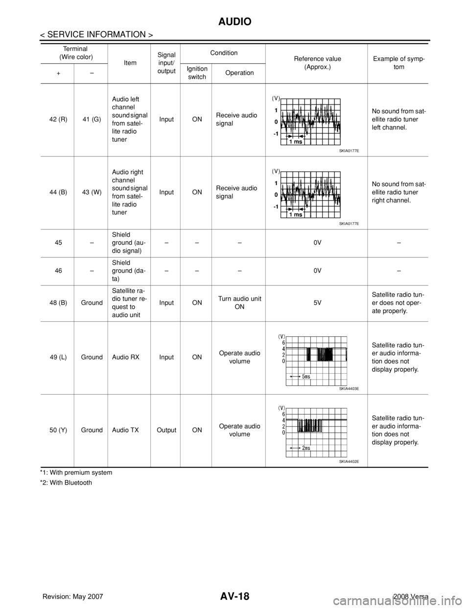
*2: With Bluetooth42 (R) 41 (G)Audio left
channel
sound signal
from satel-
lite radio
tunerInput ONReceive audio
signalNo sound from sat-
ellite radio tuner
left channel.
44 (B) 43 (W)Audio right
channel
sound signal
from satel-
lite radio
tunerInput ONReceive audio
signalNo sound from sat-
ellite radio tuner
right channel.
45 –Shield
ground (au-
dio signal)–– – 0V –
46 –Shield
ground (da-
ta)–– – 0V –
48 (B) GroundSatellite ra-
dio tuner re-
quest to
audio unitInput ONTurn audio unit
ON 5VSatellite radio tun-
er does not oper-
ate properly.
49 (L) Ground Audio RX Input ONOperate audio
volume Satellite radio tun-
er audio informa-
tion does not
display properly.
50 (Y) Ground Audio TX Output ONOperate audio
volume Satellite radio tun-
er audio informa-
tion does not
display properly. Te r m i n a l
(Wire color)
ItemSignal
input/
outputCondition
Reference value
(Approx.)Example of symp-
tom
+–Ignition
switchOperation
SKIA0177E
SKIA0177E
SKIA4403E
SKIA4402E
Page 378 of 2771
AUDIO
AV-19
< SERVICE INFORMATION >
C
D
E
F
G
H
I
J
L
MA
B
AV
N
O
P
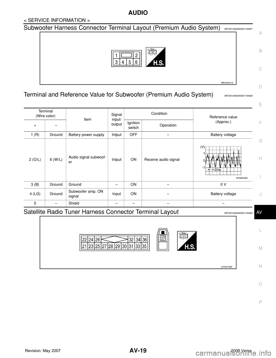
Subwoofer Harness Connector Terminal Layout (Premium Audio System)INFOID:0000000001704657
Terminal and Reference Value for Subwoofer (Premium Audio System)INFOID:0000000001704658
Satellite Radio Tuner Harness Connector Terminal LayoutINFOID:0000000001704659
WKIA5441E
Te r m i n a l
(Wire color)
ItemSignal
input/
outputCondition
Reference value
(Approx.)
+–Ignition
switchOperation
1 (R) Ground Battery power supply Intput OFF – Battery voltage
2 (O/L) 6 (W/L)Audio signal subwoof-
erIntput ON Receive audio signal
3 (B) Ground Ground – ON – 0 V
4 (LG) GroundSubwoofer amp. ON
signalInput ON – Battery voltage
5–Shield –– – –
SKIB3609E
LKIA0735E
Page 379 of 2771
AV-20
< SERVICE INFORMATION >
AUDIO
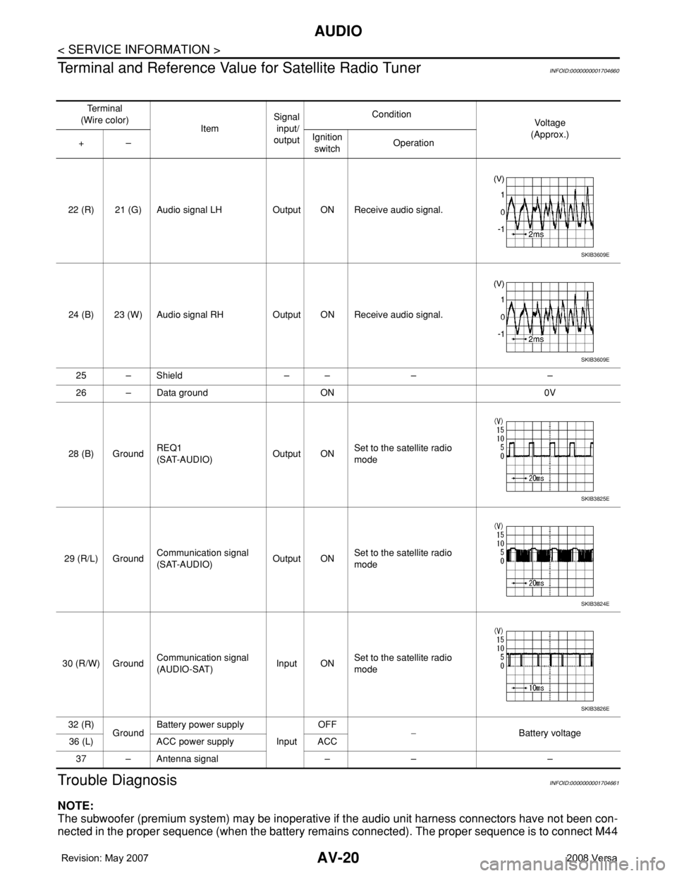
Terminal and Reference Value for Satellite Radio Tuner
INFOID:0000000001704660
Trouble DiagnosisINFOID:0000000001704661
NOTE:
The subwoofer (premium system) may be inoperative if the audio unit harness connectors have not been con-
nected in the proper sequence (when the battery remains connected). The proper sequence is to connect M44
Te r m i n a l
(Wire color)
ItemSignal
input/
outputCondition
Vol tag e
(Approx.)
+–Ignition
switchOperation
22 (R) 21 (G) Audio signal LH Output ON Receive audio signal.
24 (B) 23 (W) Audio signal RH Output ON Receive audio signal.
25 – Shield – – – –
26 – Data ground ON 0V
28 (B) GroundREQ1
(SAT-AUDIO)Output ONSet to the satellite radio
mode
29 (R/L) GroundCommunication signal
(SAT-AUDIO)Output ONSet to the satellite radio
mode
30 (R/W) GroundCommunication signal
(AUDIO-SAT)Input ONSet to the satellite radio
mode
32 (R)
GroundBattery power supply
InputOFF
−Battery voltage
36 (L) ACC power supply ACC
37 – Antenna signal – – –
SKIB3609E
SKIB3609E
SKIB3825E
SKIB3824E
SKIB3826E
Page 381 of 2771
AV-22
< SERVICE INFORMATION >
AUDIO
Power Supply Circuit Inspection
INFOID:0000000001704663
1.CHECK FUSE
Check that the following fuses of the subwoofer (premium system) and audio unit are not blown.
OK or NG
OK >> GO TO 2.
NG >> If fuse is blown, be sure to eliminate cause of blown fuse before installing new fuse. Refer to PG-
3 .
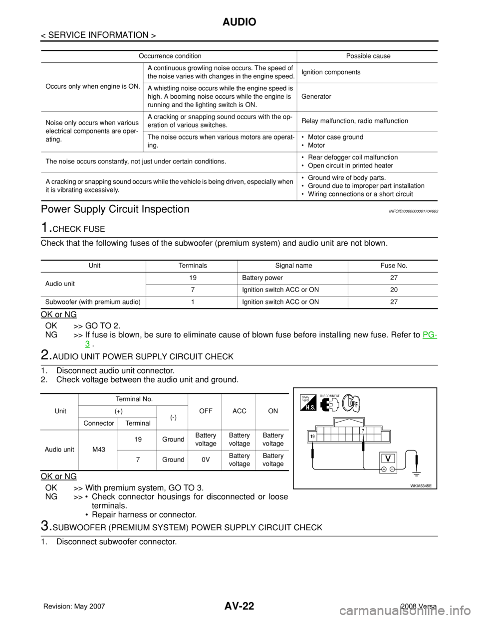
2.AUDIO UNIT POWER SUPPLY CIRCUIT CHECK
1. Disconnect audio unit connector.
2. Check voltage between the audio unit and ground.
OK or NG
OK >> With premium system, GO TO 3.
NG >> • Check connector housings for disconnected or loose
terminals.
• Repair harness or connector.
3.SUBWOOFER (PREMIUM SYSTEM) POWER SUPPLY CIRCUIT CHECK
1. Disconnect subwoofer connector.
Occurrence condition Possible cause
Occurs only when engine is ON.A continuous growling noise occurs. The speed of
the noise varies with changes in the engine speed.Ignition components
A whistling noise occurs while the engine speed is
high. A booming noise occurs while the engine is
running and the lighting switch is ON.Generator
Noise only occurs when various
electrical components are oper-
ating.A cracking or snapping sound occurs with the op-
eration of various switches.Relay malfunction, radio malfunction
The noise occurs when various motors are operat-
ing.• Motor case ground
• Motor
The noise occurs constantly, not just under certain conditions.• Rear defogger coil malfunction
• Open circuit in printed heater
A cracking or snapping sound occurs while the vehicle is being driven, especially when
it is vibrating excessively.• Ground wire of body parts.
• Ground due to improper part installation
• Wiring connections or a short circuit
Unit Terminals Signal name Fuse No.
Audio unit19 Battery power 27
7 Ignition switch ACC or ON 20
Subwoofer (with premium audio) 1 Ignition switch ACC or ON 27
UnitTe r m i n a l N o .
OFF ACC ON (+)
(-)
Connector Terminal
Audio unit M4319 GroundBattery
voltageBattery
voltageBattery
voltage
7Ground0VBattery
voltageBattery
voltage
WKIA5345E
Page 382 of 2771
AUDIO
AV-23
< SERVICE INFORMATION >
C
D
E
F
G
H
I
J
L
MA
B
AV
N
O
P
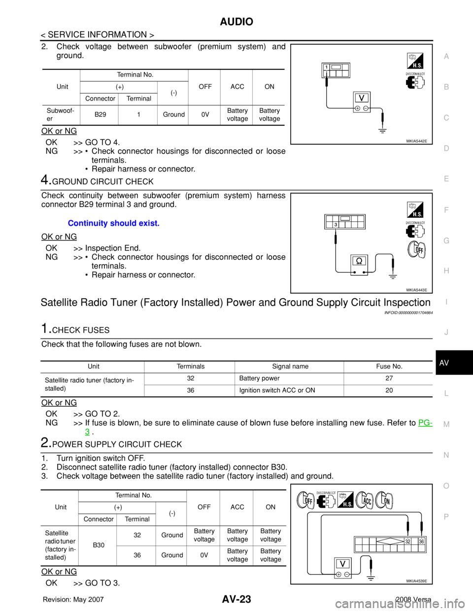
2. Check voltage between subwoofer (premium system) and
ground.
OK or NG
OK >> GO TO 4.
NG >> • Check connector housings for disconnected or loose
terminals.
• Repair harness or connector.
4.GROUND CIRCUIT CHECK
Check continuity between subwoofer (premium system) harness
connector B29 terminal 3 and ground.
OK or NG
OK >> Inspection End.
NG >> • Check connector housings for disconnected or loose
terminals.
• Repair harness or connector.
Satellite Radio Tuner (Factory Installed) Power and Ground Supply Circuit Inspection
INFOID:0000000001704664
1.CHECK FUSES
Check that the following fuses are not blown.
OK or NG
OK >> GO TO 2.
NG >> If fuse is blown, be sure to eliminate cause of blown fuse before installing new fuse. Refer to PG-
3 .
2.POWER SUPPLY CIRCUIT CHECK
1. Turn ignition switch OFF.
2. Disconnect satellite radio tuner (factory installed) connector B30.
3. Check voltage between the satellite radio tuner (factory installed) and ground.
OK or NG
OK >> GO TO 3.
UnitTe r m i n a l N o .
OFF ACC ON (+)
(-)
Connector Terminal
Subwoof-
erB29 1 Ground 0VBattery
voltageBattery
voltage
WKIA5442E
Continuity should exist.
WKIA5443E
Unit Terminals Signal name Fuse No.
Satellite radio tuner (factory in-
stalled)32 Battery power 27
36 Ignition switch ACC or ON 20
UnitTerminal No.
OFF ACC ON (+)
(-)
Connector Terminal
Satellite
radio tuner
(factory in-
stalled)B3032 GroundBattery
voltageBattery
voltageBattery
voltage
36 Ground 0VBattery
voltageBattery
voltage
WKIA4539E