ground NISSAN TIIDA 2008 Service Owner's Manual
[x] Cancel search | Manufacturer: NISSAN, Model Year: 2008, Model line: TIIDA, Model: NISSAN TIIDA 2008Pages: 2771, PDF Size: 60.61 MB
Page 134 of 2771
AT-122
< SERVICE INFORMATION >
DTC P0740 TORQUE CONVERTER CLUTCH SOLENOID VALVE
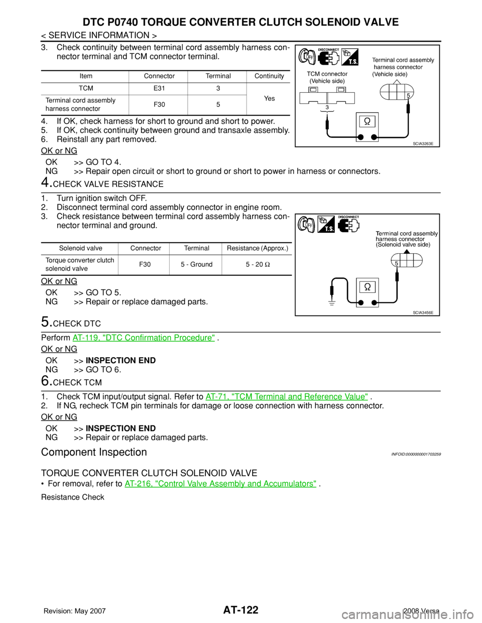
3. Check continuity between terminal cord assembly harness con-
nector terminal and TCM connector terminal.
4. If OK, check harness for short to ground and short to power.
5. If OK, check continuity between ground and transaxle assembly.
6. Reinstall any part removed.
OK or NG
OK >> GO TO 4.
NG >> Repair open circuit or short to ground or short to power in harness or connectors.
4.CHECK VALVE RESISTANCE
1. Turn ignition switch OFF.
2. Disconnect terminal cord assembly connector in engine room.
3. Check resistance between terminal cord assembly harness con-
nector terminal and ground.
OK or NG
OK >> GO TO 5.
NG >> Repair or replace damaged parts.
5.CHECK DTC
Perform AT-119, "
DTC Confirmation Procedure" .
OK or NG
OK >>INSPECTION END
NG >> GO TO 6.
6.CHECK TCM
1. Check TCM input/output signal. Refer to AT-71, "
TCM Terminal and Reference Value" .
2. If NG, recheck TCM pin terminals for damage or loose connection with harness connector.
OK or NG
OK >>INSPECTION END
NG >> Repair or replace damaged parts.
Component InspectionINFOID:0000000001703259
TORQUE CONVERTER CLUTCH SOLENOID VALVE
• For removal, refer to AT-216, "Control Valve Assembly and Accumulators" .
Resistance Check
Item Connector Terminal Continuity
TCM E31 3
Ye s
Terminal cord assembly
harness connectorF30 5
SCIA3263E
Solenoid valve Connector Terminal Resistance (Approx.)
Torque converter clutch
solenoid valveF30 5 - Ground 5 - 20 Ω
SCIA3456E
Page 135 of 2771
DTC P0740 TORQUE CONVERTER CLUTCH SOLENOID VALVE
AT-123
< SERVICE INFORMATION >
D
E
F
G
H
I
J
K
L
MA
B
AT
N
O
P
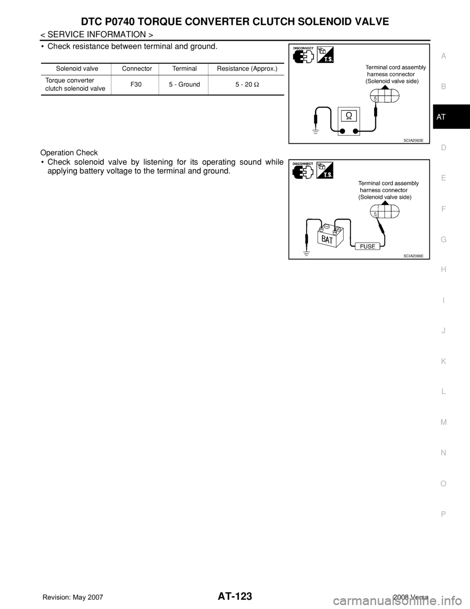
• Check resistance between terminal and ground.
Operation Check
• Check solenoid valve by listening for its operating sound while
applying battery voltage to the terminal and ground.
Solenoid valve Connector Terminal Resistance (Approx.)
Torque converter
clutch solenoid valveF30 5 - Ground 5 - 20 Ω
SCIA2063E
SCIA2066E
Page 138 of 2771

AT-126
< SERVICE INFORMATION >
DTC P0744 A/T TCC S/V FUNCTION (LOCK-UP)
During AT-55, "Cruise Test - Part 1".
Does A/T shift from D
3 to D4 at the specified speed?
YES >> GO TO 5.
NO >> Check control valve again. Repair or replace control
valve assembly.
5.CHECK DTC
Perform AT-124, "
DTC Confirmation Procedure".
OK or NG
OK >>INSPECTION END
NG >> GO TO 11. Check for proper lock-up.
6.CHECK VALVE RESISTANCE
1. Remove control valve assembly. Refer to AT-216, "
Control Valve Assembly and Accumulators".
- Line pressure solenoid valve
2. Check resistance between terminal cord assembly harness con-
nector terminal and ground. Refer to AT-130, "
Wiring Diagram -
AT - L P S V".
OK or NG
OK >> GO TO 7.
NG >> Replace solenoid valve assembly.
7.CHECK VALVE OPERATION
1. Remove control valve assembly. Refer to AT-216, "
Control Valve Assembly and Accumulators".
- Line pressure solenoid valve
2. Check solenoid valve by listening for its operating sound while
applying battery voltage to the terminal and ground. Refer to AT-
130, "Wiring Diagram - AT - LPSV".
OK or NG
OK >> GO TO 8.
NG >> Replace solenoid valve assembly.
8.CHECK CONTROL VALVE
1. Disassemble control valve assembly. Refer to AT-263, "
Control Valve Assembly".
2. Check line pressure circuit valves for sticking.
- Pressure regulator valve
- Pilot valve
- Pressure modifier valve
OK or NG
OK >> GO TO 9.
NG >> Repair control valve.
9.CHECK SHIFT-UP (D3 TO D4)
SCIA7190E
Solenoid valve Connectror Terminal Resistance (Approx.)
Line pressure solenoid
valveF30 4 - Ground 2.5 - 5 Ω
SCIA3457E
SCIA3275E
Page 139 of 2771

DTC P0744 A/T TCC S/V FUNCTION (LOCK-UP)
AT-127
< SERVICE INFORMATION >
D
E
F
G
H
I
J
K
L
MA
B
AT
N
O
P
During AT-55, "Cruise Test - Part 1".
Does A/T shift from D
3 to D4 at the specified speed?
YES >> GO TO 10.
NO >> Check control valve again. Repair or replace control
valve assembly.
10.CHECK DTC
Perform AT-124, "
DTC Confirmation Procedure".
OK or NG
OK >>INSPECTION END
NG >> GO TO 11. Check for proper lock-up.
11 .CHECK LOCK-UP
During AT-55, "
Cruise Test - Part 1".
A/T perform lock-up at the specified speed?
YES >> Perform “Cruise test — Part 1” again and return to the
start point of this test group.
NO >> GO TO 12.
12.CHECK VALVE RESISTANCE
1. Remove control valve assembly. Refer to AT-216, "
Control Valve Assembly and Accumulators".
- Torque converter clutch solenoid valve
2. Check resistance between terminal cord assembly harness con-
nector terminal and ground. Refer to AT-120, "
Wiring Diagram -
AT - T C V".
OK or NG
OK >> GO TO 13.
NG >> Replace solenoid valve assembly.
13.CHECK VALVE OPERATION
1. Remove control valve assembly. Refer to AT-216, "
Control Valve Assembly and Accumulators".
- Torque converter clutch solenoid valve
SCIA7190E
SCIA7191E
Solenoid valve Connectror Terminal Resistance (Approx.)
Torque converter clutch
solenoid valveF30 5 - Ground 5 - 20 Ω
SCIA2063E
Page 140 of 2771
AT-128
< SERVICE INFORMATION >
DTC P0744 A/T TCC S/V FUNCTION (LOCK-UP)
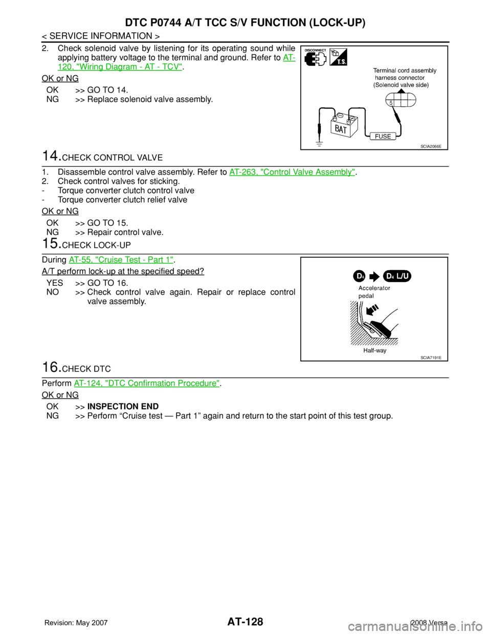
2. Check solenoid valve by listening for its operating sound while
applying battery voltage to the terminal and ground. Refer to AT-
120, "Wiring Diagram - AT - TCV".
OK or NG
OK >> GO TO 14.
NG >> Replace solenoid valve assembly.
14.CHECK CONTROL VALVE
1. Disassemble control valve assembly. Refer to AT-263, "
Control Valve Assembly".
2. Check control valves for sticking.
- Torque converter clutch control valve
- Torque converter clutch relief valve
OK or NG
OK >> GO TO 15.
NG >> Repair control valve.
15.CHECK LOCK-UP
During AT-55, "
Cruise Test - Part 1".
A/T perform lock-up at the specified speed?
YES >> GO TO 16.
NO >> Check control valve again. Repair or replace control
valve assembly.
16.CHECK DTC
Perform AT-124, "
DTC Confirmation Procedure".
OK or NG
OK >>INSPECTION END
NG >> Perform “Cruise test — Part 1” again and return to the start point of this test group.
SCIA2066E
SCIA7191E
Page 143 of 2771
DTC P0745 LINE PRESSURE SOLENOID VALVE
AT-131
< SERVICE INFORMATION >
D
E
F
G
H
I
J
K
L
MA
B
AT
N
O
P
Diagnosis ProcedureINFOID:0000000001703272
1.CHECK INPUT SIGNAL
With CONSULT-III
1. Turn ignition switch ON. (Do not start engine.)
2. Select “MAIN SIGNALS” in “DATA MONITOR” mode for “A/T” with CONSULT-III.
3. Read out the value of “LINE PRES DTY” while driving. Check the value changes according to driving
speed.
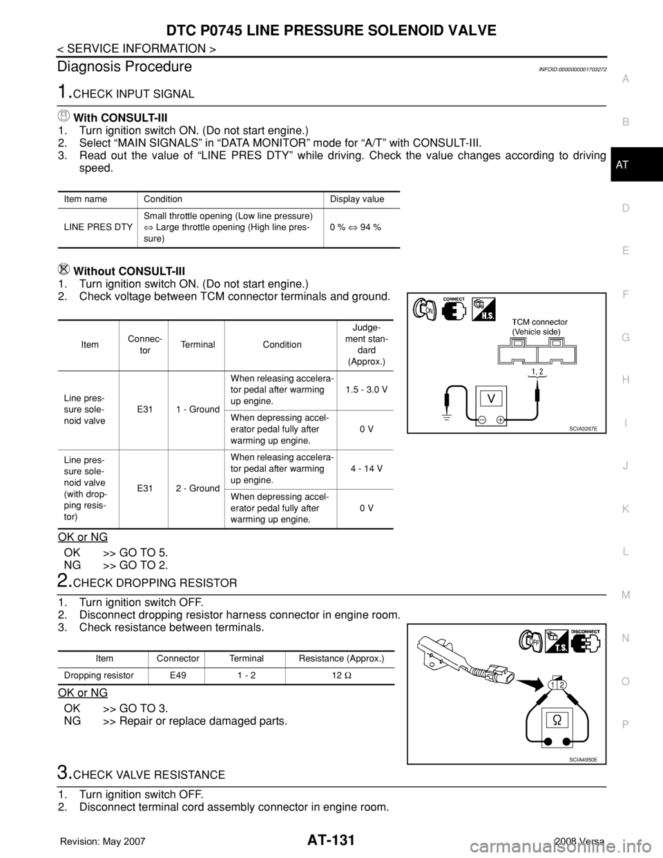
Without CONSULT-III
1. Turn ignition switch ON. (Do not start engine.)
2. Check voltage between TCM connector terminals and ground.
OK or NG
OK >> GO TO 5.
NG >> GO TO 2.
2.CHECK DROPPING RESISTOR
1. Turn ignition switch OFF.
2. Disconnect dropping resistor harness connector in engine room.
3. Check resistance between terminals.
OK or NG
OK >> GO TO 3.
NG >> Repair or replace damaged parts.
3.CHECK VALVE RESISTANCE
1. Turn ignition switch OFF.
2. Disconnect terminal cord assembly connector in engine room.
Item name Condition Display value
LINE PRES DTYSmall throttle opening (Low line pressure)
⇔ Large throttle opening (High line pres-
sure)0 % ⇔ 94 %
ItemConnec-
torTerminal ConditionJudge-
ment stan-
dard
(Approx.)
Line pres-
sure sole-
noid valveE31 1 - GroundWhen releasing accelera-
tor pedal after warming
up engine.1.5 - 3.0 V
When depressing accel-
erator pedal fully after
warming up engine.0 V
Line pres-
sure sole-
noid valve
(with drop-
ping resis-
tor)E31 2 - GroundWhen releasing accelera-
tor pedal after warming
up engine.4 - 14 V
When depressing accel-
erator pedal fully after
warming up engine.0 V
SCIA3267E
Item Connector Terminal Resistance (Approx.)
Dropping resistor E49 1 - 2 12 Ω
SCIA4950E
Page 144 of 2771
AT-132
< SERVICE INFORMATION >
DTC P0745 LINE PRESSURE SOLENOID VALVE
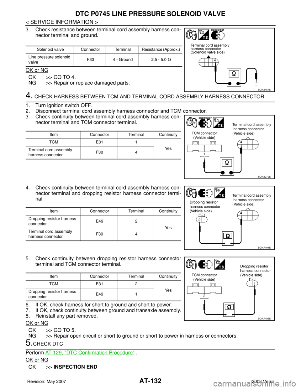
3. Check resistance between terminal cord assembly harness con-
nector terminal and ground.
OK or NG
OK >> GO TO 4.
NG >> Repair or replace damaged parts.
4. CHECK HARNESS BETWEEN TCM AND TERMINAL CORD ASSEMBLY HARNESS CONNECTOR
1. Turn ignition switch OFF.
2. Disconnect terminal cord assembly harness connector and TCM connector.
3. Check continuity between terminal cord assembly harness con-
nector terminal and TCM connector terminal.
4. Check continuity between terminal cord assembly harness con-
nector terminal and dropping resistor harness connector termi-
nal.
5. Check continuity between dropping resistor harness connector
terminal and TCM connector terminal.
6. If OK, check harness for short to ground and short to power.
7. If OK, check continuity between ground and transaxle assembly.
8. Reinstall any part removed.
OK or NG
OK >> GO TO 5.
NG >> Repair open circuit or short to ground or short to power in harness or connectors.
5.CHECK DTC
Perform AT-129, "
DTC Confirmation Procedure" .
OK or NG
OK >>INSPECTION END
Solenoid valve Connector Terminal Resistance (Approx.)
Line pressure solenoid
valveF30 4 - Ground 2.5 - 5.0 Ω
SCIA3457E
Item Connector Terminal Continuity
TCM E31 1
Ye s
Terminal cord assembly
harness connectorF30 4
SCIA3272E
Item Connector Terminal Continuity
Dropping resistor harness
connectorE49 2
Ye s
Terminal cord assembly
harness connectorF30 4
SCIA7194E
Item Connector Terminal Continuity
TCM E31 2
Ye s
Dropping resistor harness
connectorE49 1
SCIA7195E
Page 145 of 2771
DTC P0745 LINE PRESSURE SOLENOID VALVE
AT-133
< SERVICE INFORMATION >
D
E
F
G
H
I
J
K
L
MA
B
AT
N
O
P
NG >> GO TO 6.
6.CHECK TCM
1. Check TCM input/output signal. Refer to AT-71, "
TCM Terminal and Reference Value" .
2. If NG, recheck TCM pin terminals for damage or loose connection with harness connector.
OK or NG
OK >>INSPECTION END
NG >> Repair or replace damaged parts.
Component InspectionINFOID:0000000001703273
LINE PRESSURE SOLENOID VALVE
• For removal, refer to AT-216, "Control Valve Assembly and Accumulators" .
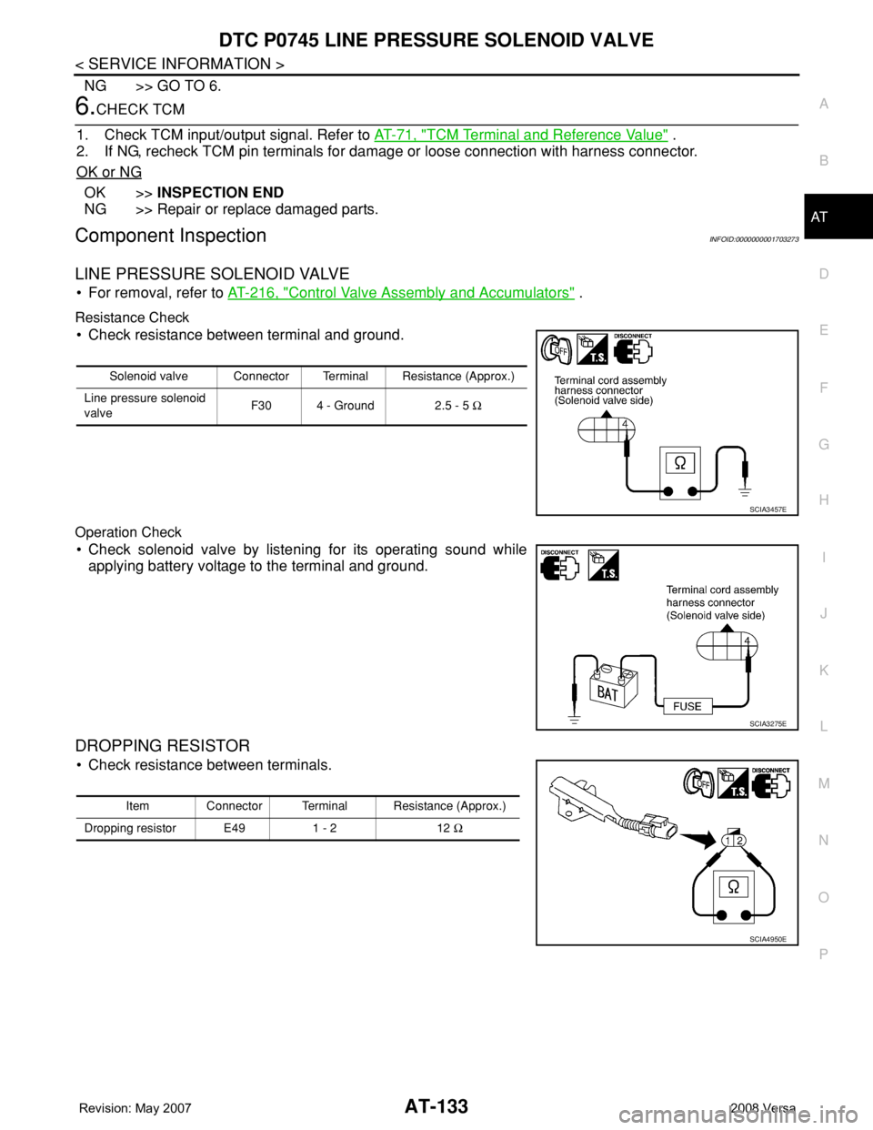
Resistance Check
• Check resistance between terminal and ground.
Operation Check
• Check solenoid valve by listening for its operating sound while
applying battery voltage to the terminal and ground.
DROPPING RESISTOR
• Check resistance between terminals.
Solenoid valve Connector Terminal Resistance (Approx.)
Line pressure solenoid
valveF30 4 - Ground 2.5 - 5 Ω
SCIA3457E
SCIA3275E
Item Connector Terminal Resistance (Approx.)
Dropping resistor E49 1 - 2 12 Ω
SCIA4950E
Page 148 of 2771
AT-136
< SERVICE INFORMATION >
DTC P0750 SHIFT SOLENOID VALVE A
Diagnosis Procedure
INFOID:0000000001703280
1.CHECK INPUT SIGNAL
With CONSULT-III
1. Start engine.
2. Select “MAIN SIGNALS” in “DATA MONITOR” mode for “A/T” with CONSULT-III.
3. Read out the value of “SHIFT S/V A” while driving.
Check the value changes according to driving speed.
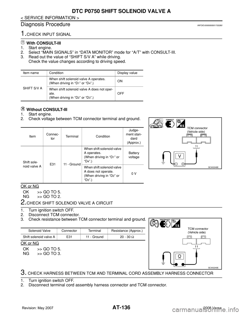
Without CONSULT-III
1. Start engine.
2. Check voltage between TCM connector terminal and ground.
OK or NG
OK >> GO TO 5.
NG >> GO TO 2.
2.CHECK SHIFT SOLENOID VALVE A CIRCUIT
1. Turn ignition switch OFF.
2. Disconnect TCM connector.
3. Check resistance between TCM connector terminal and ground.
OK or NG
OK >> GO TO 5.
NG >> GO TO 3.
3. CHECK HARNESS BETWEEN TCM AND TERMINAL CORD ASSEMBLY HARNESS CONNECTOR
1. Turn ignition switch OFF.
2. Disconnect terminal cord assembly harness connector and TCM connector.
Item name Condition Display value
SHIFT S/V AWhen shift solenoid valve A operates.
(When driving in “D
1” or “D4”.)ON
When shift solenoid valve A does not oper-
ate.
(When driving in “D
2” or “D3”.)OFF
ItemConnec-
torTerminal ConditionJudge-
ment stan-
dard
(Approx.)
Shift sole-
noid valve AE31 11 - GroundWhen shift solenoid valve
A operates.
(When driving in “D
1” or
“D
4”.)Battery
voltage
When shift solenoid valve
A does not operate.
(When driving in “D
2” or
“D
3”.)0 V
SCIA3248E
Solenoid Valve Connector Terminal Resistance (Approx.)
Shift solenoid valve A E31 11 - Ground 20 - 30 Ω
SCIA3249E
Page 149 of 2771
DTC P0750 SHIFT SOLENOID VALVE A
AT-137
< SERVICE INFORMATION >
D
E
F
G
H
I
J
K
L
MA
B
AT
N
O
P
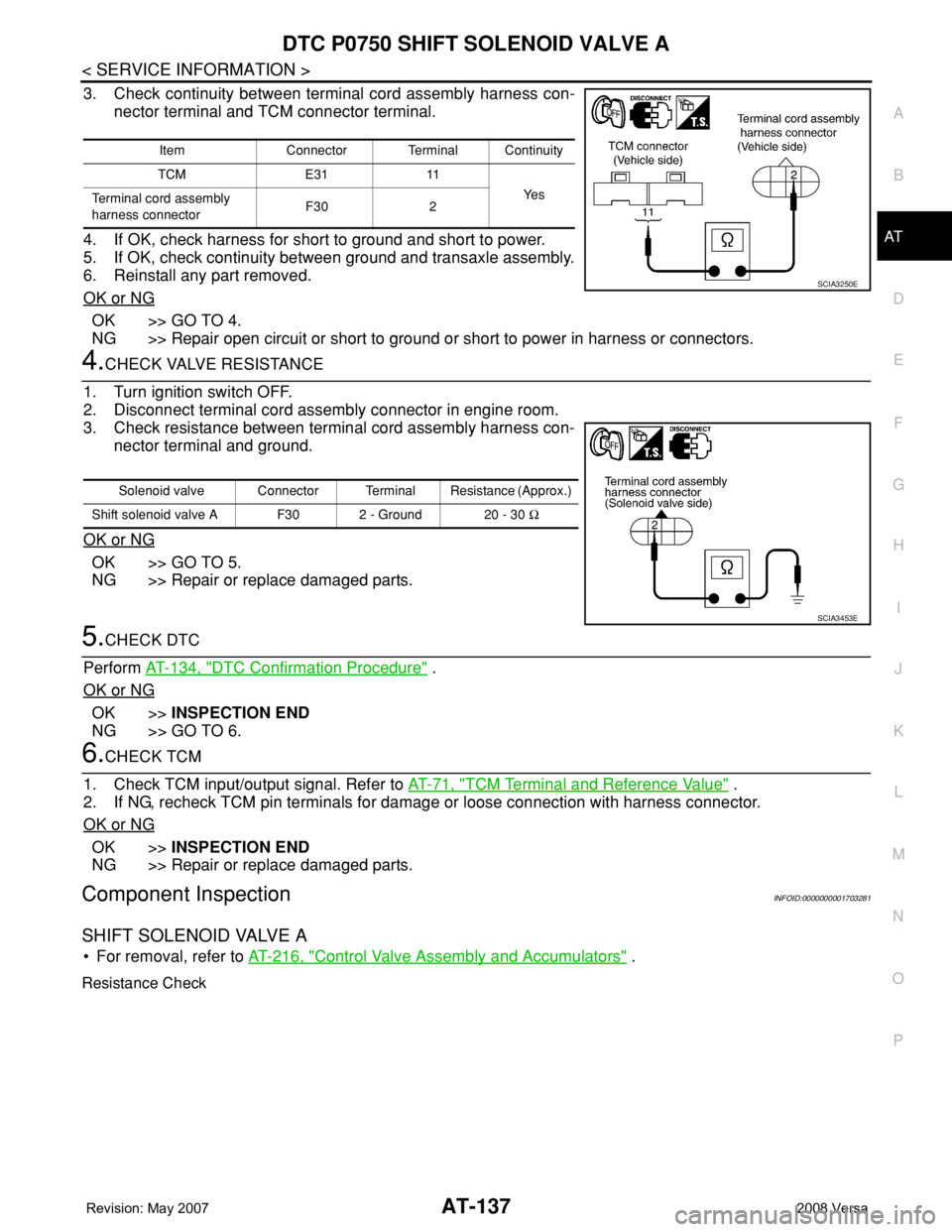
3. Check continuity between terminal cord assembly harness con-
nector terminal and TCM connector terminal.
4. If OK, check harness for short to ground and short to power.
5. If OK, check continuity between ground and transaxle assembly.
6. Reinstall any part removed.
OK or NG
OK >> GO TO 4.
NG >> Repair open circuit or short to ground or short to power in harness or connectors.
4.CHECK VALVE RESISTANCE
1. Turn ignition switch OFF.
2. Disconnect terminal cord assembly connector in engine room.
3. Check resistance between terminal cord assembly harness con-
nector terminal and ground.
OK or NG
OK >> GO TO 5.
NG >> Repair or replace damaged parts.
5.CHECK DTC
Perform AT-134, "
DTC Confirmation Procedure" .
OK or NG
OK >>INSPECTION END
NG >> GO TO 6.
6.CHECK TCM
1. Check TCM input/output signal. Refer to AT-71, "
TCM Terminal and Reference Value" .
2. If NG, recheck TCM pin terminals for damage or loose connection with harness connector.
OK or NG
OK >>INSPECTION END
NG >> Repair or replace damaged parts.
Component InspectionINFOID:0000000001703281
SHIFT SOLENOID VALVE A
• For removal, refer to AT-216, "Control Valve Assembly and Accumulators" .
Resistance Check
Item Connector Terminal Continuity
TCM E31 11
Ye s
Terminal cord assembly
harness connectorF30 2
SCIA3250E
Solenoid valve Connector Terminal Resistance (Approx.)
Shift solenoid valve A F30 2 - Ground 20 - 30 Ω
SCIA3453E