ground NISSAN TIIDA 2008 Service Workshop Manual
[x] Cancel search | Manufacturer: NISSAN, Model Year: 2008, Model line: TIIDA, Model: NISSAN TIIDA 2008Pages: 2771, PDF Size: 60.61 MB
Page 189 of 2771
TROUBLE DIAGNOSIS FOR SYMPTOMS
AT-177
< SERVICE INFORMATION >
D
E
F
G
H
I
J
K
L
MA
B
AT
N
O
P
OD OFF indicator lamp does not come on for about 2 seconds when turning ignition switch to ON.
DIAGNOSTIC PROCEDURE
1.CHECK CAN COMMUNICATION LINE
Perform self-diagnosis. Refer to AT-73, "
CONSULT-III Function (A/T)" .
Is a malfunction in CAN communication indicated in the results?
YES >> Check CAN communication line. Refer to AT- 8 3 .
NO >> GO TO 2.
2.CHECK TCM POWER SOURCE
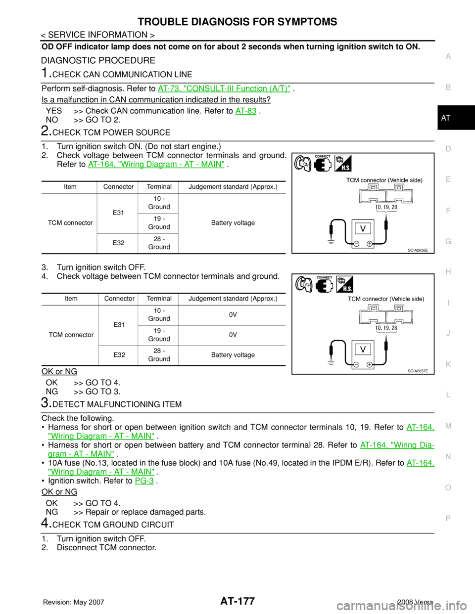
1. Turn ignition switch ON. (Do not start engine.)
2. Check voltage between TCM connector terminals and ground.
Refer to AT-164, "
Wiring Diagram - AT - MAIN" .
3. Turn ignition switch OFF.
4. Check voltage between TCM connector terminals and ground.
OK or NG
OK >> GO TO 4.
NG >> GO TO 3.
3.DETECT MALFUNCTIONING ITEM
Check the following.
• Harness for short or open between ignition switch and TCM connector terminals 10, 19. Refer to AT-164,
"Wiring Diagram - AT - MAIN" .
• Harness for short or open between battery and TCM connector terminal 28. Refer to AT-164, "
Wiring Dia-
gram - AT - MAIN" .
• 10A fuse (No.13, located in the fuse block) and 10A fuse (No.49, located in the IPDM E/R). Refer to AT-164,
"Wiring Diagram - AT - MAIN" .
• Ignition switch. Refer to PG-3
.
OK or NG
OK >> GO TO 4.
NG >> Repair or replace damaged parts.
4.CHECK TCM GROUND CIRCUIT
1. Turn ignition switch OFF.
2. Disconnect TCM connector.
Item Connector Terminal Judgement standard (Approx.)
TCM connectorE3110 -
Ground
Battery voltage 19 -
Ground
E3228 -
Ground
SCIA2656E
Item Connector Terminal Judgement standard (Approx.)
TCM connectorE3110 -
Ground0V
19 -
Ground0V
E3228 -
GroundBattery voltage
SCIA2657E
Page 190 of 2771
AT-178
< SERVICE INFORMATION >
TROUBLE DIAGNOSIS FOR SYMPTOMS
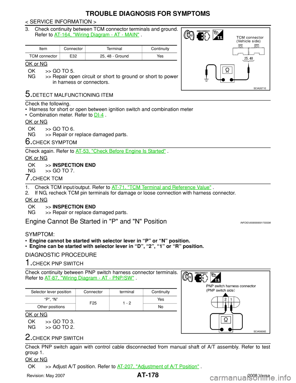
3. Check continuity between TCM connector terminals and ground.
Refer to AT-164, "
Wiring Diagram - AT - MAIN" .
OK or NG
OK >> GO TO 5.
NG >> Repair open circuit or short to ground or short to power
in harness or connectors.
5.DETECT MALFUNCTIONING ITEM
Check the following.
• Harness for short or open between ignition switch and combination meter
• Combination meter. Refer to DI-4
.
OK or NG
OK >> GO TO 6.
NG >> Repair or replace damaged parts.
6.CHECK SYMPTOM
Check again. Refer to AT-53, "
Check Before Engine Is Started" .
OK or NG
OK >>INSPECTION END
NG >> GO TO 7.
7.CHECK TCM
1. Check TCM input/output. Refer to AT-71, "
TCM Terminal and Reference Value" .
2. If NG, recheck TCM pin terminals for damage or loose connection with harness connector.
OK or NG
OK >>INSPECTION END
NG >> Repair or replace damaged parts.
Engine Cannot Be Started in "P" and "N" PositionINFOID:0000000001703336
SYMPTOM:
•Engine cannot be started with selector lever in “P” or “N” position.
•Engine can be started with selector lever in “D”, “2”, “1” or “R” position.
DIAGNOSTIC PROCEDURE
1.CHECK PNP SWITCH
Check continuity between PNP switch harness connector terminals.
Refer to AT-87, "
Wiring Diagram - AT - PNP/SW" .
OK or NG
OK >> GO TO 3.
NG >> GO TO 2.
2.CHECK PNP SWITCH
Check PNP switch again with control cable disconnected from manual shaft of A/T assembly. Refer to test
group 1.
OK or NG
OK >> Adjust A/T position. Refer to AT-207, "Adjustment of A/T Position" .
Item Connector Terminal Continuity
TCM connector E32 25, 48 - Ground Yes
SCIA2671E
Selector lever position Connector terminal Continuity
“P”, “N”
F25 1 - 2Ye s
Other positions No
SCIA5606E
Page 205 of 2771
TROUBLE DIAGNOSIS FOR SYMPTOMS
AT-193
< SERVICE INFORMATION >
D
E
F
G
H
I
J
K
L
MA
B
AT
N
O
P
OK >> GO TO 6.
NG >> Repair or replace damaged parts.
6.CHECK SYMPTOM
Check again. Refer to AT-55, "
Cruise Test - Part 1" .
OK or NG
OK >>INSPECTION END
NG >> GO TO 7.
7.CHECK TCM
1. Check TCM input/output signals. Refer to AT-71, "
TCM Terminal and Reference Value" .
2. If NG, recheck TCM pin terminals for damage or loose connection with harness connector.
OK or NG
OK >>INSPECTION END
NG >> Repair or replace damaged parts.
A/T Does Not Shift: D4→ D3, When OD OFFINFOID:0000000001703350
SYMPTOM:
A/T does not shift from D4 to D3 when OD OFF (OD OFF indicator lamp is on) on “Cruise Test — Part
3”.
DIAGNOSTIC PROCEDURE
1.CHECK CAN COMMUNICATION LINE
Perform self-diagnosis. Refer to AT-73, "
CONSULT-III Function (A/T)" or AT-78, "Diagnosis Procedure without
CONSULT-III" .
Is a malfunction in CAN communication indicated in the results?
YES >> Check CAN communication line. Refer to AT- 8 3 .
NO >> GO TO 2.
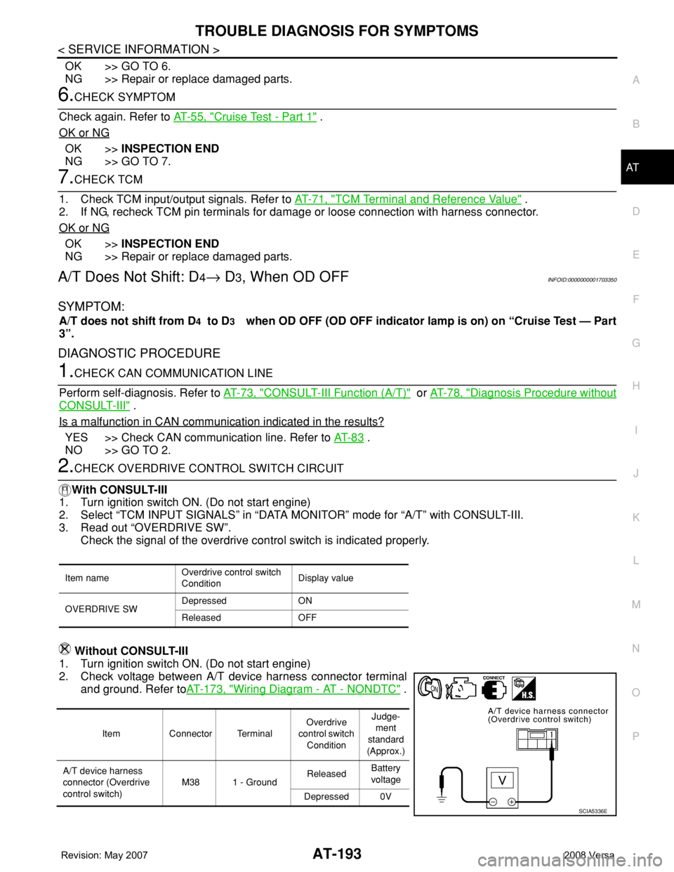
2.CHECK OVERDRIVE CONTROL SWITCH CIRCUIT
With CONSULT-III
1. Turn ignition switch ON. (Do not start engine)
2. Select “TCM INPUT SIGNALS” in “DATA MONITOR” mode for “A/T” with CONSULT-III.
3. Read out “OVERDRIVE SW”.
Check the signal of the overdrive control switch is indicated properly.
Without CONSULT-III
1. Turn ignition switch ON. (Do not start engine)
2. Check voltage between A/T device harness connector terminal
and ground. Refer toAT-173, "
Wiring Diagram - AT - NONDTC" .
Item nameOverdrive control switch
ConditionDisplay value
OVERDRIVE SWDepressed ON
Released OFF
Item Connector TerminalOverdrive
control switch
ConditionJudge-
ment
standard
(Approx.)
A/T device harness
connector (Overdrive
control switch)M38 1 - GroundReleasedBattery
voltage
Depressed 0V
SCIA5336E
Page 207 of 2771
TROUBLE DIAGNOSIS FOR SYMPTOMS
AT-195
< SERVICE INFORMATION >
D
E
F
G
H
I
J
K
L
MA
B
AT
N
O
P
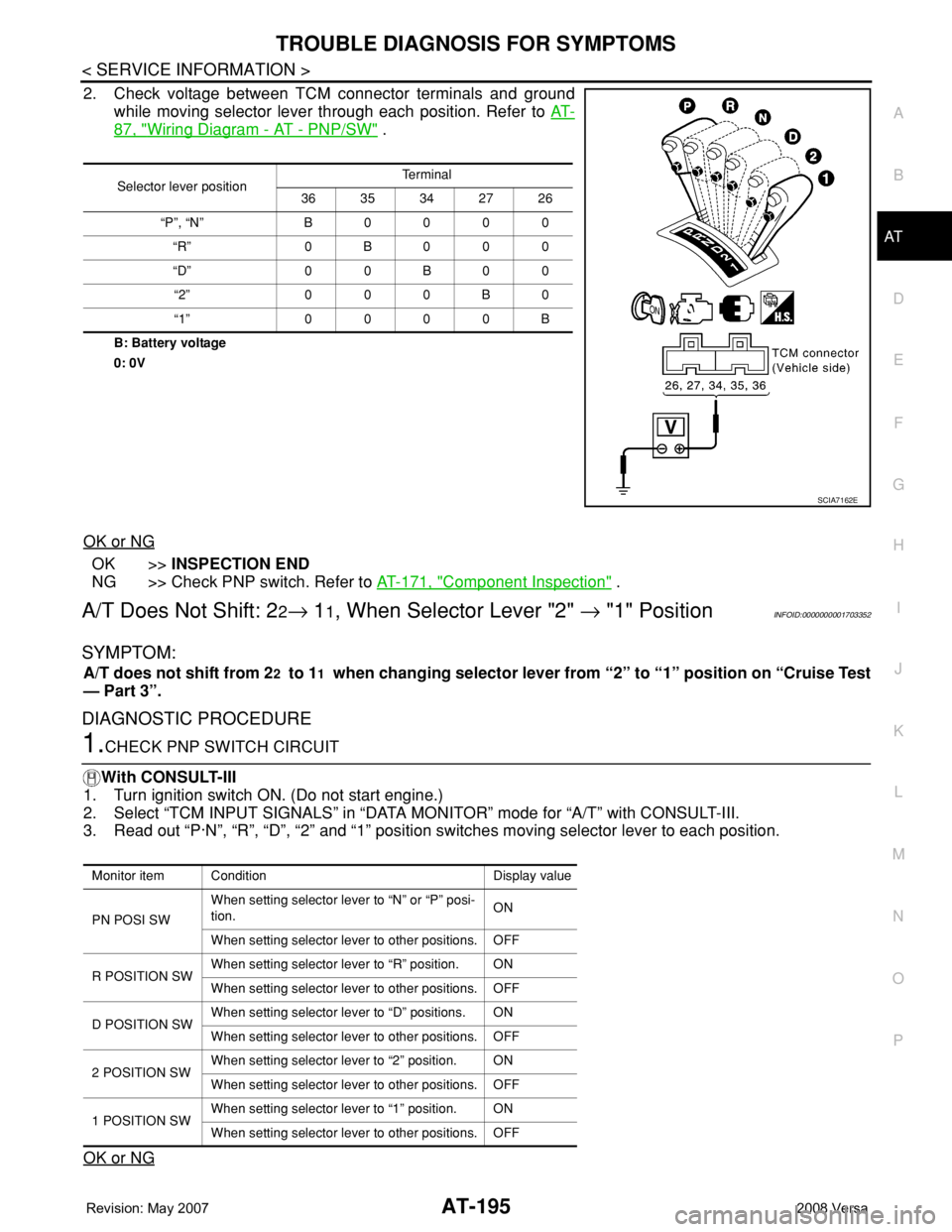
2. Check voltage between TCM connector terminals and ground
while moving selector lever through each position. Refer to AT-
87, "Wiring Diagram - AT - PNP/SW" .
B: Battery voltage
0: 0V
OK or NG
OK >>INSPECTION END
NG >> Check PNP switch. Refer to AT-171, "
Component Inspection" .
A/T Does Not Shift: 22→ 11, When Selector Lever "2" → "1" PositionINFOID:0000000001703352
SYMPTOM:
A/T does not shift from 22 to 11 when changing selector lever from “2” to “1” position on “Cruise Test
— Part 3”.
DIAGNOSTIC PROCEDURE
1.CHECK PNP SWITCH CIRCUIT
With CONSULT-III
1. Turn ignition switch ON. (Do not start engine.)
2. Select “TCM INPUT SIGNALS” in “DATA MONITOR” mode for “A/T” with CONSULT-III.
3. Read out “P·N”, “R”, “D”, “2” and “1” position switches moving selector lever to each position.
OK or NG
Selector lever positionTe r m i n a l
36 35 34 27 26
“P”, “N” B 0 0 0 0
“R” 0B000
“D” 0 0 B 0 0
“2” 0 0 0 B 0
“1” 0 0 0 0 B
SCIA7162E
Monitor item Condition Display value
PN POSI SWWhen setting selector lever to “N” or “P” posi-
tion.ON
When setting selector lever to other positions. OFF
R POSITION SWWhen setting selector lever to “R” position. ON
When setting selector lever to other positions. OFF
D POSITION SWWhen setting selector lever to “D” positions. ON
When setting selector lever to other positions. OFF
2 POSITION SWWhen setting selector lever to “2” position. ON
When setting selector lever to other positions. OFF
1 POSITION SWWhen setting selector lever to “1” position. ON
When setting selector lever to other positions. OFF
Page 208 of 2771
AT-196
< SERVICE INFORMATION >
TROUBLE DIAGNOSIS FOR SYMPTOMS
OK >> GO TO 3
NG >> Check PNP switch. Refer to AT-171, "
Component Inspection" .
2.CHECK PNP SWITCH CIRCUIT
Without CONSULT-III
1. Turn ignition switch ON. (Do not start engine.)
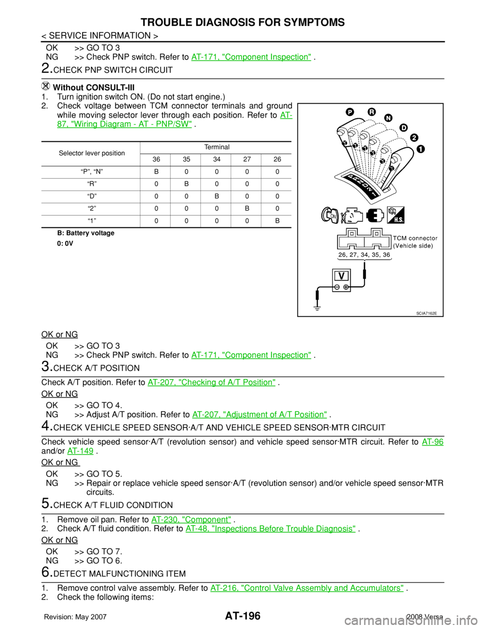
2. Check voltage between TCM connector terminals and ground
while moving selector lever through each position. Refer to AT-
87, "Wiring Diagram - AT - PNP/SW" .
B: Battery voltage
0: 0V
OK or NG
OK >> GO TO 3
NG >> Check PNP switch. Refer to AT-171, "
Component Inspection" .
3.CHECK A/T POSITION
Check A/T position. Refer to AT-207, "
Checking of A/T Position" .
OK or NG
OK >> GO TO 4.
NG >> Adjust A/T position. Refer to AT-207, "
Adjustment of A/T Position" .
4.CHECK VEHICLE SPEED SENSOR·A/T AND VEHICLE SPEED SENSOR·MTR CIRCUIT
Check vehicle speed sensor·A/T (revolution sensor) and vehicle speed sensor·MTR circuit. Refer to AT- 9 6
and/or AT-149 .
OK or NG
OK >> GO TO 5.
NG >> Repair or replace vehicle speed sensor·A/T (revolution sensor) and/or vehicle speed sensor·MTR
circuits.
5.CHECK A/T FLUID CONDITION
1. Remove oil pan. Refer to AT-230, "
Component" .
2. Check A/T fluid condition. Refer to AT-48, "
Inspections Before Trouble Diagnosis" .
OK or NG
OK >> GO TO 7.
NG >> GO TO 6.
6.DETECT MALFUNCTIONING ITEM
1. Remove control valve assembly. Refer to AT-216, "
Control Valve Assembly and Accumulators" .
2. Check the following items:
Selector lever positionTe r m i n a l
36 35 34 27 26
“P”, “N” B0000
“R” 0B000
“D” 0 0 B 0 0
“2” 000B0
“1” 0000B
SCIA7162E
Page 210 of 2771
AT-198
< SERVICE INFORMATION >
TROUBLE DIAGNOSIS FOR SYMPTOMS
Without CONSULT-III
1. Turn ignition switch ON. (Do not start engine)
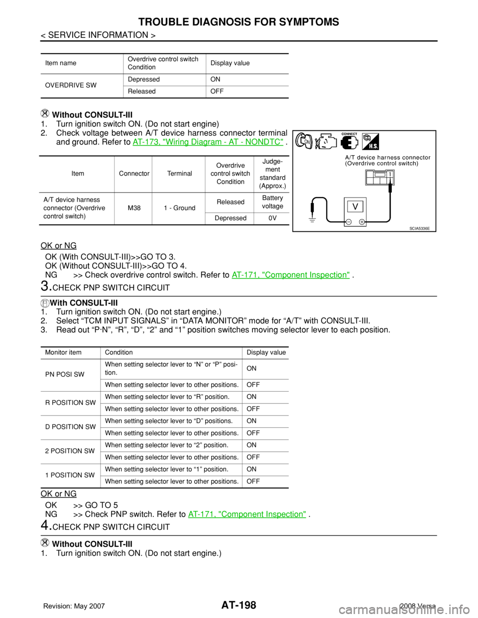
2. Check voltage between A/T device harness connector terminal
and ground. Refer to AT-173, "
Wiring Diagram - AT - NONDTC" .
OK or NG
OK (With CONSULT-III)>>GO TO 3.
OK (Without CONSULT-III)>>GO TO 4.
NG >> Check overdrive control switch. Refer to AT-171, "
Component Inspection" .
3.CHECK PNP SWITCH CIRCUIT
With CONSULT-III
1. Turn ignition switch ON. (Do not start engine.)
2. Select “TCM INPUT SIGNALS” in “DATA MONITOR” mode for “A/T” with CONSULT-III.
3. Read out “P·N”, “R”, “D”, “2” and “1” position switches moving selector lever to each position.
OK or NG
OK >> GO TO 5
NG >> Check PNP switch. Refer to AT-171, "
Component Inspection" .
4.CHECK PNP SWITCH CIRCUIT
Without CONSULT-III
1. Turn ignition switch ON. (Do not start engine.)
Item nameOverdrive control switch
ConditionDisplay value
OVERDRIVE SWDepressed ON
Released OFF
Item Connector TerminalOverdrive
control switch
ConditionJudge-
ment
standard
(Approx.)
A/T device harness
connector (Overdrive
control switch)M38 1 - GroundReleasedBattery
voltage
Depressed 0V
SCIA5336E
Monitor item Condition Display value
PN POSI SWWhen setting selector lever to “N” or “P” posi-
tion.ON
When setting selector lever to other positions. OFF
R POSITION SWWhen setting selector lever to “R” position. ON
When setting selector lever to other positions. OFF
D POSITION SWWhen setting selector lever to “D” positions. ON
When setting selector lever to other positions. OFF
2 POSITION SWWhen setting selector lever to “2” position. ON
When setting selector lever to other positions. OFF
1 POSITION SWWhen setting selector lever to “1” position. ON
When setting selector lever to other positions. OFF
Page 211 of 2771
TROUBLE DIAGNOSIS FOR SYMPTOMS
AT-199
< SERVICE INFORMATION >
D
E
F
G
H
I
J
K
L
MA
B
AT
N
O
P
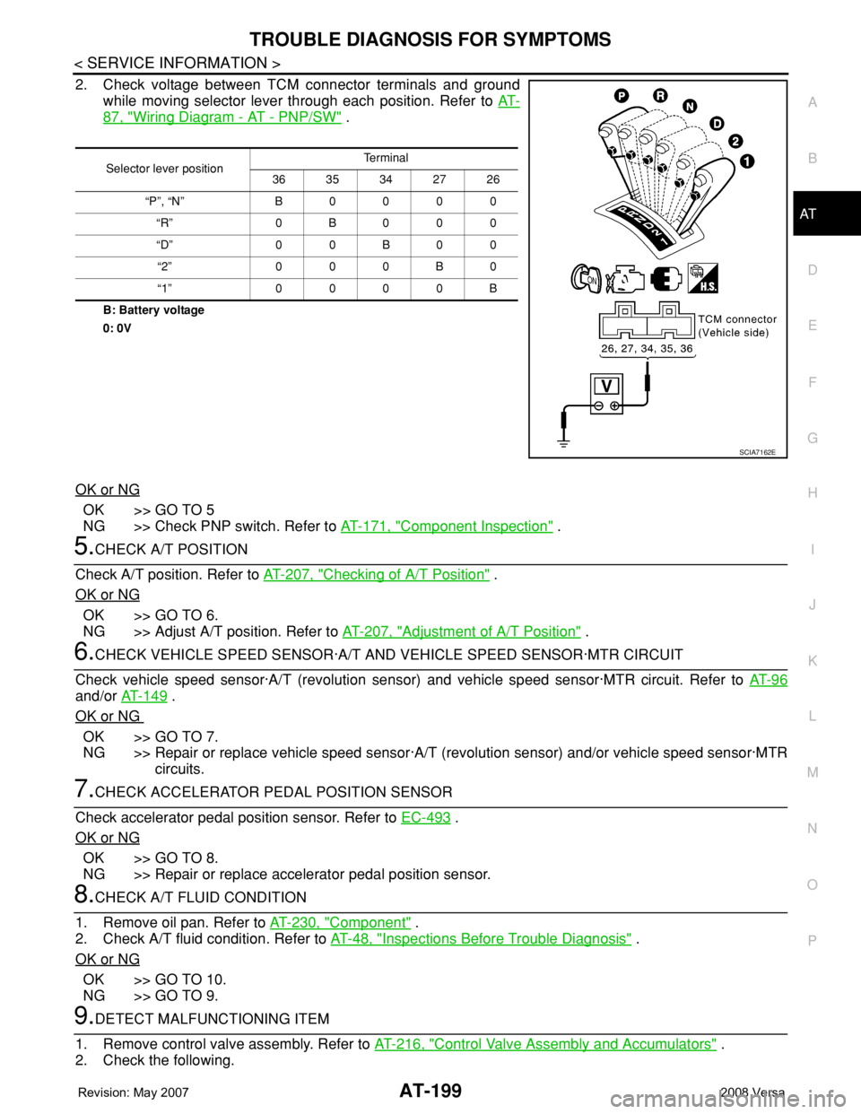
2. Check voltage between TCM connector terminals and ground
while moving selector lever through each position. Refer to AT-
87, "Wiring Diagram - AT - PNP/SW" .
B: Battery voltage
0: 0V
OK or NG
OK >> GO TO 5
NG >> Check PNP switch. Refer to AT-171, "
Component Inspection" .
5.CHECK A/T POSITION
Check A/T position. Refer to AT-207, "
Checking of A/T Position" .
OK or NG
OK >> GO TO 6.
NG >> Adjust A/T position. Refer to AT-207, "
Adjustment of A/T Position" .
6.CHECK VEHICLE SPEED SENSOR·A/T AND VEHICLE SPEED SENSOR·MTR CIRCUIT
Check vehicle speed sensor·A/T (revolution sensor) and vehicle speed sensor·MTR circuit. Refer to AT- 9 6
and/or AT-149 .
OK or NG
OK >> GO TO 7.
NG >> Repair or replace vehicle speed sensor·A/T (revolution sensor) and/or vehicle speed sensor·MTR
circuits.
7.CHECK ACCELERATOR PEDAL POSITION SENSOR
Check accelerator pedal position sensor. Refer to EC-493
.
OK or NG
OK >> GO TO 8.
NG >> Repair or replace accelerator pedal position sensor.
8.CHECK A/T FLUID CONDITION
1. Remove oil pan. Refer to AT-230, "
Component" .
2. Check A/T fluid condition. Refer to AT-48, "
Inspections Before Trouble Diagnosis" .
OK or NG
OK >> GO TO 10.
NG >> GO TO 9.
9.DETECT MALFUNCTIONING ITEM
1. Remove control valve assembly. Refer to AT-216, "
Control Valve Assembly and Accumulators" .
2. Check the following.
Selector lever positionTe r m i n a l
36 35 34 27 26
“P”, “N” B 0 0 0 0
“R” 0B000
“D” 0 0 B 0 0
“2” 0 0 0 B 0
“1” 0 0 0 0 B
SCIA7162E
Page 223 of 2771
A/T SHIFT LOCK SYSTEM
AT-211
< SERVICE INFORMATION >
D
E
F
G
H
I
J
K
L
MA
B
AT
N
O
P
•Selector lever can be moved from “P” position with ignition key in ON position and brake pedal
released.
•Selector lever can be moved from “P” position when ignition switch is removed from key cylinder.
SYMPTOM 2:
•Ignition key cannot be removed when selector lever is set to “P” position.
•Ignition key can be removed when selector lever is set to any position except “P” position.
1.CHECK KEY INTERLOCK CABLE
Check key interlock cable for damage.
OK or NG
OK >> GO TO 2.
NG >> Repair key interlock cable. Refer to AT-213, "
Removal and Installation" .
2.CHECK A/T POSITION
Check A/T position. Refer to AT-207, "
Checking of A/T Position" .
OK or NG
OK >> GO TO 3.
NG >> Adjust control cable. Refer to AT-207, "
Adjustment of A/T Position" .
3.CHECK SHIFT LOCK SOLENOID AND PARK POSITION SWITCH
1. Turn ignition switch ON. (Do not start engine.)
2. Selector lever is set in “P” position.
3. Check operation sound.
OK or NG
OK >>INSPECTION END
NG >> GO TO 4.
4.CHECK POWER SOURCE
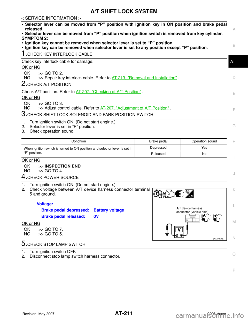
1. Turn ignition switch ON. (Do not start engine.)
2. Check voltage between A/T device harness connector terminal
5 and ground.
OK or NG
OK >> GO TO 7.
NG >> GO TO 5.
5.CHECK STOP LAMP SWITCH
1. Turn ignition switch OFF.
2. Disconnect stop lamp switch harness connector.
Condition Brake pedal Operation sound
When ignition switch is turned to ON position and selector lever is set in
“P” position.Depressed Yes
Released No
Voltage:
Brake pedal depressed: Battery voltage
Brake pedal released: 0V
SCIA7171E
Page 224 of 2771
AT-212
< SERVICE INFORMATION >
A/T SHIFT LOCK SYSTEM
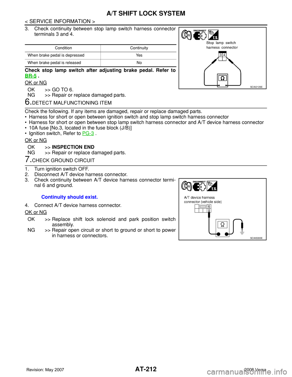
3. Check continuity between stop lamp switch harness connector
terminals 3 and 4.
Check stop lamp switch after adjusting brake pedal. Refer to
BR-5
.
OK or NG
OK >> GO TO 6.
NG >> Repair or replace damaged parts.
6.DETECT MALFUNCTIONING ITEM
Check the following. If any items are damaged, repair or replace damaged parts.
• Harness for short or open between ignition switch and stop lamp switch harness connector
• Harness for short or open between stop lamp switch harness connector and A/T device harness connector
• 10A fuse [No.3, located in the fuse block (J/B)]
• Ignition switch, Refer to PG-3
.
OK or NG
OK >>INSPECTION END
NG >> Repair or replace damaged parts.
7.CHECK GROUND CIRCUIT
1. Turn ignition switch OFF.
2. Disconnect A/T device harness connector.
3. Check continuity between A/T device harness connector termi-
nal 6 and ground.
4. Connect A/T device harness connector.
OK or NG
OK >> Replace shift lock solenoid and park position switch
assembly.
NG >> Repair open circuit or short to ground or short to power
in harness or connectors.
Condition Continuity
When brake pedal is depressed Yes
When brake pedal is released No
SCIA2126E
Continuity should exist.
SCIA5000E
Page 360 of 2771

AV-1
ELECTRICAL
C
D
E
F
G
H
I
J
L
M
SECTION AV
A
B
AV
N
O
P
CONTENTS
AUDIO, VISUAL, NAVIGATION & TELEPHONE SYS-
TEM
SERVICE INFORMATION ............................2
PRECAUTIONS ...................................................2
Precaution for Supplemental Restraint System
(SRS) "AIR BAG" and "SEAT BELT PRE-TEN-
SIONER" ...................................................................
2
PREPARATION ...................................................3
Commercial Service Tool ..........................................3
AUDIO .................................................................4
Component Parts Location ........................................4
System Description ...................................................4
Schematic .................................................................6
Wiring Diagram - AUDIO - .........................................8
Audio Unit (Base System) Harness Connector
Terminal Layout ......................................................
15
Terminal and Reference Value for Audio Unit
(Base System) .........................................................
15
Audio Unit (Mid Level and Premium System) Har-
ness Connector Terminal Layout ............................
16
Terminal and Reference Value for Audio Unit (Mid
Level and Premium System) ...................................
16
Subwoofer Harness Connector Terminal Layout
(Premium Audio System) ........................................
19
Terminal and Reference Value for Subwoofer
(Premium Audio System) ........................................
19
Satellite Radio Tuner Harness Connector Termi-
nal Layout ................................................................
19
Terminal and Reference Value for Satellite Radio
Tuner .......................................................................
20
Trouble Diagnosis ...................................................20
Noise Inspection ......................................................21
Power Supply Circuit Inspection .............................22
Satellite Radio Tuner (Factory Installed) Power
and Ground Supply Circuit Inspection .....................
23
Satellite Radio Tuner (Factory Installed) Commu-
nication Circuit Inspection .......................................
24
Satellite Radio Tuner (Factory Installed) Left
Channel Audio Signal Circuit Inspection .................
26
Satellite Radio Tuner (Factory Installed) Right
Channel Audio Signal Circuit Inspection .................
26
Steering Switch Check (With Bluetooth) ..................27
Sound Is Not Heard from Front Door Speaker
(Base System) .........................................................
29
Sound Is Not Heard from Rear Door Speaker
(Base System) .........................................................
30
Sound Is Not Heard from Front Door Speaker or
Tweeter (Mid Level and Premium System) .............
31
Sound Is Not Heard from Rear Door Speaker (Mid
Level and Premium System) ...................................
32
Sound Is Not Heard from Subwoofer (Premium
System) ...................................................................
34
Removal and Installation .........................................36
AUDIO ANTENNA .............................................41
Location of Antenna .................................................41
Removal and Installation of Roof Antenna ..............41
TELEPHONE .....................................................43
Component Parts and Harness Connector Loca-
tion ...........................................................................
43
System Description ..................................................43
Wiring Diagram - H/PHON - ....................................45
Bluetooth Control Unit Harness Connector Termi-
nal Layout ................................................................
47
Terminal and Reference Value for Bluetooth Con-
trol Unit ....................................................................
47
Bluetooth Control Unit Self-Diagnosis Function ......48
Workflow ..................................................................49
Power Supply and Ground Circuit Inspection for
Bluetooth Control Unit .............................................
49
Basic Inspection of Hands-Free Phone ...................50
Steering Wheel Audio Control Switch Does Not
Operate ....................................................................
51
Voice Activated Control Function Does Not Oper-
ate ............................................................................
52
Removal and Installation .........................................54