oil pressure NISSAN TIIDA 2008 Service Manual Online
[x] Cancel search | Manufacturer: NISSAN, Model Year: 2008, Model line: TIIDA, Model: NISSAN TIIDA 2008Pages: 2771, PDF Size: 60.61 MB
Page 2172 of 2771
HEADLAMP (FOR CANADA) - DAYTIME LIGHT SYSTEM -
LT-35
< SERVICE INFORMATION >
C
D
E
F
G
H
I
J
L
MA
B
LT
N
O
P
Aiming AdjustmentINFOID:0000000001704393
PREPARATION BEFORE ADJUSTING
Before performing aiming adjustment, check the following.
1. Keep all tires inflated to correct pressures.
2. Place vehicle on level surface.
3. Set that there is no-load in vehicle other than the driver (or equivalent weight placed in driver's position).
Coolant, engine oil filled up to correct level and full fuel tank, spare tire, jack and tools are properly
stowed.
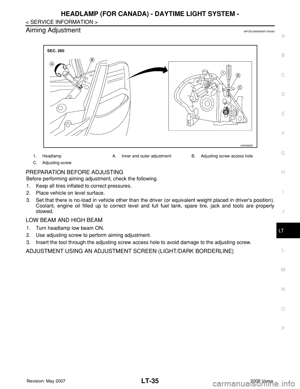
LOW BEAM AND HIGH BEAM
1. Turn headlamp low beam ON.
2. Use adjusting screw to perform aiming adjustment.
3. Insert the tool through the adjusting screw access hole to avoid damage to the adjusting screw.
ADJUSTMENT USING AN ADJUSTMENT SCREEN (LIGHT/DARK BORDERLINE)
1. Headlamp A. Inner and outer adjustment B. Adjusting screw access hole
C. Adjusting screw
LKIA0930E
Page 2183 of 2771
LT-46
< SERVICE INFORMATION >
FRONT FOG LAMP
1. Check continuity between front fog lamp harness connector and
ground.
OK or NG
OK >> Replace IPDM E/R. Refer to PG-26, "Removal and
Installation of IPDM E/R" .
NG >> Repair harness or connector.
Aiming AdjustmentINFOID:0000000001704409
The front fog lamp is a semi-sealed beam type which uses a replaceable halogen bulb. Before performing
aiming adjustment, make sure of the following.
• Keep all tires inflated to correct pressure.
• Place vehicle on level surface.
• Set that there is no-load in vehicle other than the driver (or equivalent weight placed in driver’s position).
Coolant, engine oil filled up to correct level and full fuel tank, spare tire, jack and tools are properly stowed.
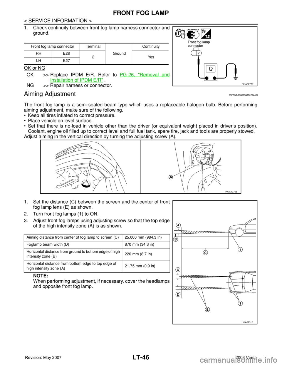
Adjust aiming in the vertical direction by turning the adjusting screw (A).
1. Set the distance (C) between the screen and the center of front
fog lamp lens (E) as shown.
2. Turn front fog lamps (1) to ON.
3. Adjust front fog lamps using adjusting screw so that the top edge
of the high intensity zone (A) is as shown.
NOTE:
When performing adjustment, if necessary, cover the headlamps
and opposite front fog lamp.
Front fog lamp connector Terminal
Ground Continuity
RH E28
2Yes
LH E27
PKIA6277E
PKIC1070E
Aiming distance from center of fog lamp to screen (C) 25,000 mm (984.3 in)
Foglamp beam width (D) 870 mm (34.3 in)
Horizontal distance from ground to bottom edge of high
intensity zone (B)220 mm (8.7 in)
Horizontal distance from bottom edge to top edge of
high intensity zone (A)21.75 mm (0.9 in)
LKIA0931E
Page 2253 of 2771
PREPARATION
LU-3
< SERVICE INFORMATION >
C
D
E
F
G
H
I
J
K
L
MA
LU
N
P O
PREPARATION
Special Service ToolINFOID:0000000001702515
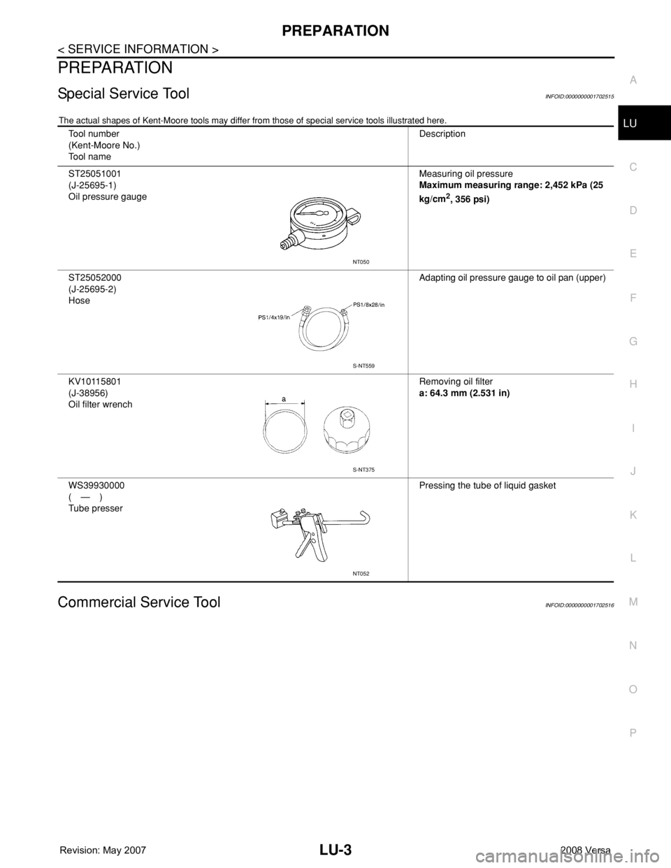
The actual shapes of Kent-Moore tools may differ from those of special service tools illustrated here.
Commercial Service ToolINFOID:0000000001702516
Tool number
(Kent-Moore No.)
Tool nameDescription
ST25051001
(J-25695-1)
Oil pressure gaugeMeasuring oil pressure
Maximum measuring range: 2,452 kPa (25
kg/cm
2, 356 psi)
ST25052000
(J-25695-2)
HoseAdapting oil pressure gauge to oil pan (upper)
KV10115801
(J-38956)
Oil filter wrenchRemoving oil filter
a: 64.3 mm (2.531 in)
WS39930000
(—)
Tube presserPressing the tube of liquid gasket
NT050
S-NT559
S-NT375
NT052
Page 2254 of 2771
LU-4
< SERVICE INFORMATION >
PREPARATION
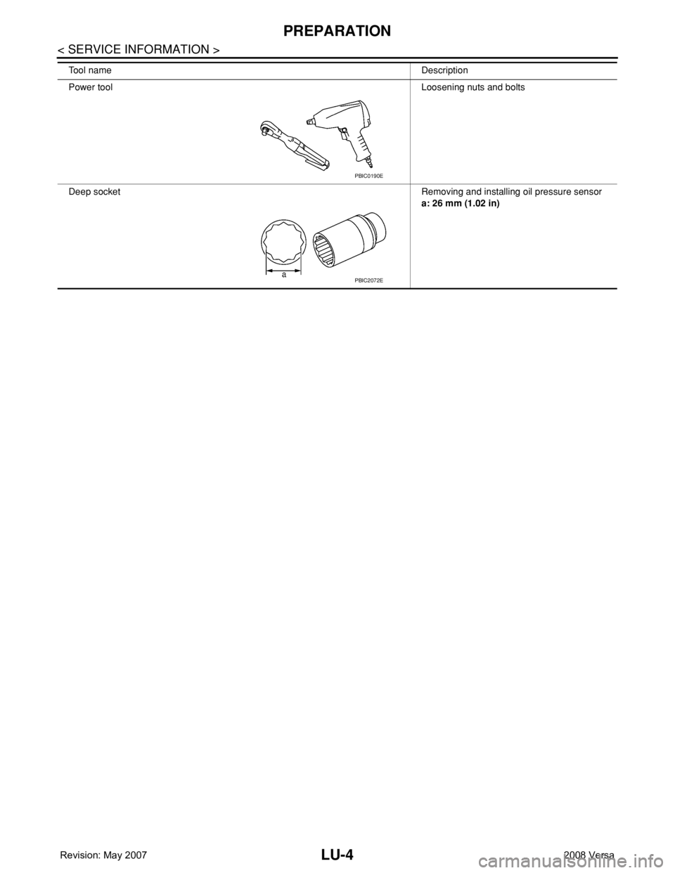
Tool nameDescription
Power toolLoosening nuts and bolts
Deep socketRemoving and installing oil pressure sensor
a: 26 mm (1.02 in)
PBIC0190E
PBIC2072E
Page 2256 of 2771
LU-6
< SERVICE INFORMATION >
ENGINE OIL
ENGINE OIL
InspectionINFOID:0000000001702518
ENGINE OIL LEVEL
NOTE:
Before starting engine, park vehicle on a level surface and check the engine oil level. If engine is already
started, stop it and allow 10 minutes before checking.
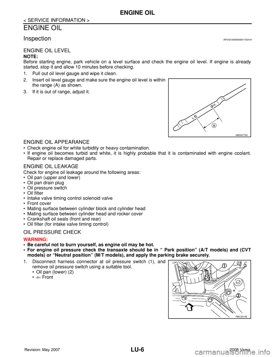
1. Pull out oil level gauge and wipe it clean.
2. Insert oil level gauge and make sure the engine oil level is within
the range (A) as shown.
3. If it is out of range, adjust it.
ENGINE OIL APPEARANCE
• Check engine oil for white turbidity or heavy contamination.
• If engine oil becomes turbid and white, it is highly probable that it is contaminated with engine coolant.
Repair or replace damaged parts.
ENGINE OIL LEAKAGE
Check for engine oil leakage around the following areas:
• Oil pan (upper and lower)
• Oil pan drain plug
• Oil pressure switch
• Oil filter
• Intake valve timing control solenoid valve
• Front cover
• Mating surface between cylinder block and cylinder head
• Mating surface between cylinder head and rocker cover
• Crankshaft oil seals (front and rear)
• Oil filter (for intake valve timing control)
OIL PRESSURE CHECK
WARNING:
• Be careful not to burn yourself, as engine oil may be hot.
• For engine oil pressure check the transaxle should be in “ Park position” (A/T models) and (CVT
models) or “Neutral position” (M/T models), and apply the parking brake securely.
1. Disconnect harness connector at oil pressure switch (1), and
remove oil pressure switch using a suitable tool.
• Oil pan (lower) (2)
•⇐ Front
WBIA0776E
PBIC3310E
Page 2257 of 2771
ENGINE OIL
LU-7
< SERVICE INFORMATION >
C
D
E
F
G
H
I
J
K
L
MA
LU
N
P O
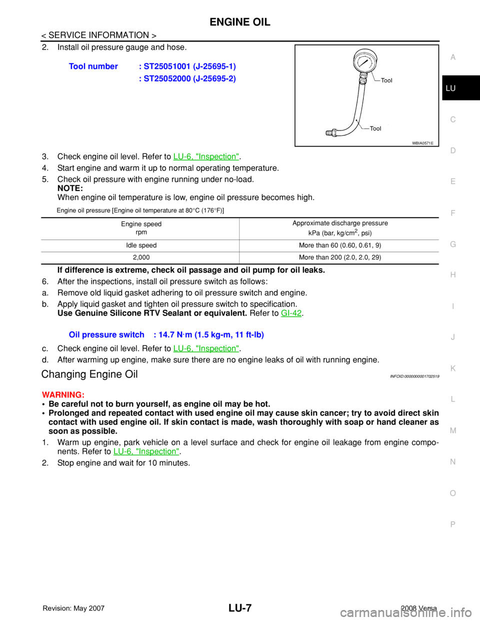
2. Install oil pressure gauge and hose.
3. Check engine oil level. Refer to LU-6, "
Inspection".
4. Start engine and warm it up to normal operating temperature.
5. Check oil pressure with engine running under no-load.
NOTE:
When engine oil temperature is low, engine oil pressure becomes high.
Engine oil pressure [Engine oil temperature at 80°C (176°F)]
If difference is extreme, check oil passage and oil pump for oil leaks.
6. After the inspections, install oil pressure switch as follows:
a. Remove old liquid gasket adhering to oil pressure switch and engine.
b. Apply liquid gasket and tighten oil pressure switch to specification.
Use Genuine Silicone RTV Sealant or equivalent. Refer to GI-42
.
c. Check engine oil level. Refer to LU-6, "
Inspection".
d. After warming up engine, make sure there are no engine leaks of oil with running engine.
Changing Engine OilINFOID:0000000001702519
WARNING:
• Be careful not to burn yourself, as engine oil may be hot.
• Prolonged and repeated contact with used engine oil may cause skin cancer; try to avoid direct skin
contact with used engine oil. If skin contact is made, wash thoroughly with soap or hand cleaner as
soon as possible.
1. Warm up engine, park vehicle on a level surface and check for engine oil leakage from engine compo-
nents. Refer to LU-6, "
Inspection".
2. Stop engine and wait for 10 minutes.Tool number : ST25051001 (J-25695-1)
: ST25052000 (J-25695-2)
WBIA0571E
Engine speed
rpm Approximate discharge pressure
kPa (bar, kg/cm2, psi)
Idle speed More than 60 (0.60, 0.61, 9)
2,000 More than 200 (2.0, 2.0, 29)
Oil pressure switch : 14.7 N·m (1.5 kg-m, 11 ft-lb)
Page 2260 of 2771

LU-10
< SERVICE INFORMATION >
SERVICE DATA AND SPECIFICATIONS (SDS)
SERVICE DATA AND SPECIFICATIONS (SDS)
Standard and LimitINFOID:0000000001702521
OIL PRESSURE
Oil Capacity
Unit: (US qt, Imp qt)
Engine speed rpm
Approximate discharge pressure kPa (bar, kg/cm2, psi)
Idle speed
2,00060 (0.60, 0.61, 9)
200 (2.0, 2.0, 29)
Drain and refillWith oil filter change Approximately 3.9 (4 1/8, 3 3/8)
Without oil filter change Approximately 3.7 (3 7/8, 3 1/4)
Dry engine (engine overhaul) Approximately 4.9 (5 1/8, 4 3/8)
Page 2278 of 2771
MA-18
< SERVICE INFORMATION >
ENGINE MAINTENANCE
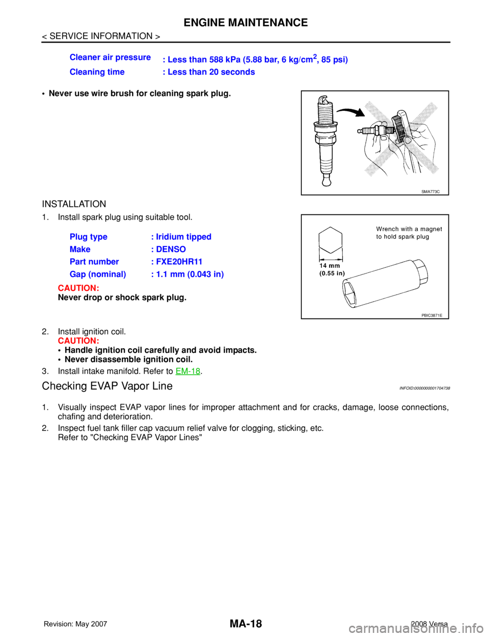
• Never use wire brush for cleaning spark plug.
INSTALLATION
1. Install spark plug using suitable tool.
CAUTION:
Never drop or shock spark plug.
2. Install ignition coil.
CAUTION:
• Handle ignition coil carefully and avoid impacts.
• Never disassemble ignition coil.
3. Install intake manifold. Refer to EM-18
.
Checking EVAP Vapor LineINFOID:0000000001704738
1. Visually inspect EVAP vapor lines for improper attachment and for cracks, damage, loose connections,
chafing and deterioration.
2. Inspect fuel tank filler cap vacuum relief valve for clogging, sticking, etc.
Refer to "Checking EVAP Vapor Lines"Cleaner air pressure
: Less than 588 kPa (5.88 bar, 6 kg/cm
2, 85 psi)
Cleaning time : Less than 20 seconds
SMA773C
Plug type : Iridium tipped
Make : DENSO
Part number : FXE20HR11
Gap (nominal) : 1.1 mm (0.043 in)
PBIC3871E
Page 2340 of 2771

MTC-2
DUCTS AND GRILLES ......................................69
Removal and Installation ........................................69
REFRIGERANT LINES ......................................74
HFC-134a (R-134a) Service Procedure .................74
Component .............................................................76
Removal and Installation of Compressor ................78
Removal and Installation of Low-Pressure Flexi-
ble Hose .................................................................
79
Removal and Installation of High-pressure Flexi-
ble Hose .................................................................
80
Removal and Installation of High-pressure Pipe ....81
Removal and Installation of Refrigerant Pressure
Sensor ....................................................................
81
Removal and Installation of Condenser ..................82
Removal and Installation of Liquid Tank .................82
Removal and Installation of Evaporator ..................83
Removal and Installation of Expansion Valve .........84
Checking of Refrigerant Leaks ................................84
Checking System for Leaks Using the Fluorescent
Leak Detector ..........................................................
85
Dye Injection ...........................................................85
Electronic Refrigerant Leak Detector ......................85
SERVICE DATA AND SPECIFICATIONS
(SDS) .................................................................
88
Compressor ............................................................88
Oil ............................................................................88
Refrigerant ..............................................................88
Engine Idling Speed ................................................88
Belt Tension ............................................................88
Page 2342 of 2771

MTC-4
< SERVICE INFORMATION >
PRECAUTIONS
- Do not allow A/C oil to come in contact with styrofoam parts. Damage may result.
General Refrigerant PrecautionINFOID:0000000001704277
WARNING:
• Avoid breathing A/C refrigerant and oil vapor or mist. Exposure may irritate eyes, nose and throat.
Use only approved recovery/recycling equipment to discharge HFC-134a (R-134a) refrigerant. If acci-
dental system discharge occurs, ventilate work area before resuming service. Additional health and
safety information may be obtained from refrigerant and oil manufacturers.
• Do not release refrigerant into the air. Use approved recovery/recycling equipment to capture the
refrigerant every time an air conditioning system is discharged.
• Always wear eye and hand protection (goggles and gloves) when working with any refrigerant or air
conditioning system.
• Do not store or heat refrigerant containers above 52°C (126° F).
• Do not heat a refrigerant container with an open flame; if container warming is required, place the
bottom of the container in a warm pail of water.
• Do not intentionally drop, puncture, or incinerate refrigerant containers.
• Keep refrigerant away from open flames: poisonous gas will be produced if refrigerant burns.
• Refrigerant will displace oxygen, therefore be certain to work in well ventilated areas to prevent suf-
focation.
• Do not pressure test or leak test HFC-134a (R-134a) service equipment and/or vehicle air condition-
ing systems with compressed air during repair. Some mixtures of air and HFC-134a (R-134a) have
been shown to be combustible at elevated pressures. These mixtures, if ignited, may cause injury or
property damage. Additional health and safety information may be obtained from refrigerant manu-
facturers.
Oil PrecautionINFOID:0000000001704278
• Use only specified oil for the HFC-134a (R-134a) A/C system and HFC-134a (R-134a) components. If oil
other than that specified is used, compressor malfunction is likely to occur.
• The specified HFC-134a (R-134a) oil rapidly absorbs moisture from the atmosphere. The following handling
precautions must be observed:
- When removing refrigerant components from a vehicle, immediately cap (seal) the component to minimize
the entry of moisture from the atmosphere.
- When installing refrigerant components to a vehicle, do not remove the caps (unseal) until just before con-
necting the components. Connect all refrigerant loop components as quickly as possible to minimize the
entry of moisture into system.
- Only use the specified oil from a sealed container. Immediately reseal containers of oil. Without proper seal-
ing, oil will become moisture saturated and should not be used.
• Avoid breathing A/C refrigerant and oil vapor or mist. Exposure may irritate eyes, nose and throat.
Use only approved recovery/recycling equipment to discharge HFC-134a (R-134a) refrigerant. If accidental
system discharge occurs, ventilate work area before resuming service. Additional health and safety informa-
tion may be obtained from refrigerant and oil manufacturers.
• Do not allow A/C oil to come in contact with styrofoam parts. Damage may result.
Precaution for Refrigerant ConnectionINFOID:0000000001704279
A new type refrigerant connection has been introduced to all refrigerant lines except the following location.
• Expansion valve to evaporator
• Refrigerant pressure sensor to condenser