oil pressure NISSAN TIIDA 2008 Service Owners Manual
[x] Cancel search | Manufacturer: NISSAN, Model Year: 2008, Model line: TIIDA, Model: NISSAN TIIDA 2008Pages: 2771, PDF Size: 60.61 MB
Page 2344 of 2771
MTC-6
< SERVICE INFORMATION >
PRECAUTIONS
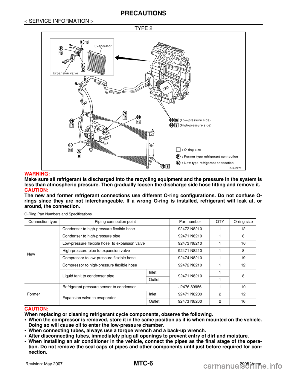
TYPE 2
WARNING:
Make sure all refrigerant is discharged into the recycling equipment and the pressure in the system is
less than atmospheric pressure. Then gradually loosen the discharge side hose fitting and remove it.
CAUTION:
The new and former refrigerant connections use different O-ring configurations. Do not confuse O-
rings since they are not interchangeable. If a wrong O-ring is installed, refrigerant will leak at, or
around, the connection.
O-Ring Part Numbers and Specifications
CAUTION:
When replacing or cleaning refrigerant cycle components, observe the following.
• When the compressor is removed, store it in the same position as it is when mounted on the vehicle.
Doing so will cause oil to enter the low-pressure chamber.
• When connecting tubes, always use a torque wrench and a back-up wrench.
• After disconnecting tubes, immediately plug all openings to prevent entry of dirt and moisture.
• When installing an air conditioner in the vehicle, connect the pipes as the final stage of the opera-
tion. Do not remove the seal caps of pipes and other components until just before required for con-
nection.
SJIA1327E
Connection type Piping connection point Part number QTY O-ring size
NewCondenser to high-pressure flexible hose 92472 N8210 1 12
Condenser to high-pressure pipe 92471 N8210 1 8
Low-pressure flexible hose to expansion valve 92473 N8210 1 16
High-pressure pipe to expansion valve 92471 N8210 1 8
Compressor to low-pressure flexible hose 92474 N8210 1 19
Compressor to high-pressure flexible hose 92472 N8210 1 12
Liquid tank to condenser pipeInlet
92471 N82101
8
Outlet 1
FormerRefrigerant pressure sensor to condenser J2476 89956 1 10
Expansion valve to evaporatorInlet 92471 N8200 2 12
Outlet 92473 N8200 2 16
Page 2346 of 2771
MTC-8
< SERVICE INFORMATION >
PRECAUTIONS
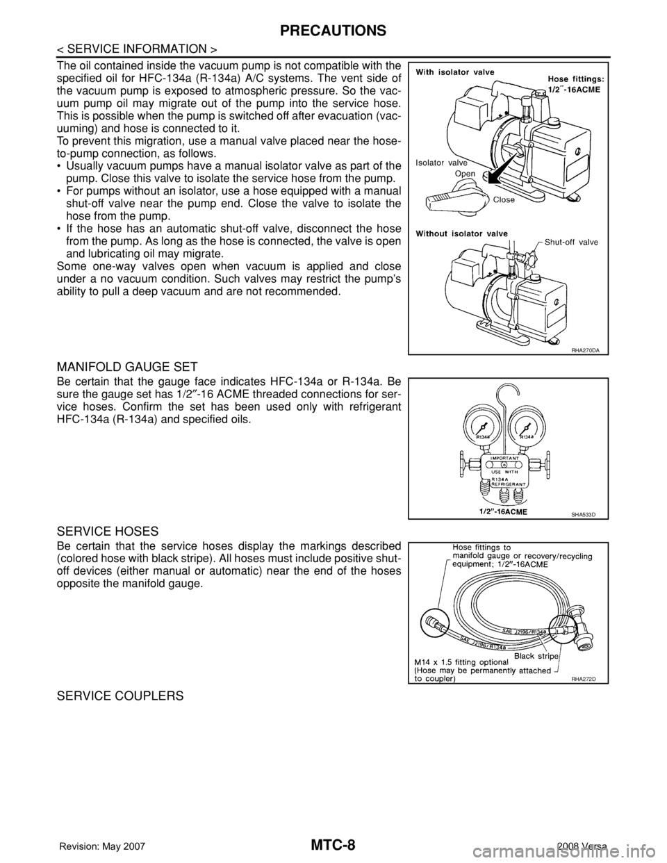
The oil contained inside the vacuum pump is not compatible with the
specified oil for HFC-134a (R-134a) A/C systems. The vent side of
the vacuum pump is exposed to atmospheric pressure. So the vac-
uum pump oil may migrate out of the pump into the service hose.
This is possible when the pump is switched off after evacuation (vac-
uuming) and hose is connected to it.
To prevent this migration, use a manual valve placed near the hose-
to-pump connection, as follows.
• Usually vacuum pumps have a manual isolator valve as part of the
pump. Close this valve to isolate the service hose from the pump.
• For pumps without an isolator, use a hose equipped with a manual
shut-off valve near the pump end. Close the valve to isolate the
hose from the pump.
• If the hose has an automatic shut-off valve, disconnect the hose
from the pump. As long as the hose is connected, the valve is open
and lubricating oil may migrate.
Some one-way valves open when vacuum is applied and close
under a no vacuum condition. Such valves may restrict the pump’s
ability to pull a deep vacuum and are not recommended.
MANIFOLD GAUGE SET
Be certain that the gauge face indicates HFC-134a or R-134a. Be
sure the gauge set has 1/2″-16 ACME threaded connections for ser-
vice hoses. Confirm the set has been used only with refrigerant
HFC-134a (R-134a) and specified oils.
SERVICE HOSES
Be certain that the service hoses display the markings described
(colored hose with black stripe). All hoses must include positive shut-
off devices (either manual or automatic) near the end of the hoses
opposite the manifold gauge.
SERVICE COUPLERS
RHA270DA
SHA533D
RHA272D
Page 2355 of 2771
OIL
MTC-17
< SERVICE INFORMATION >
C
D
E
F
G
H
I
K
L
MA
B
MTC
N
O
P
*1: If refrigerant leak is small, no addition of oil is needed.
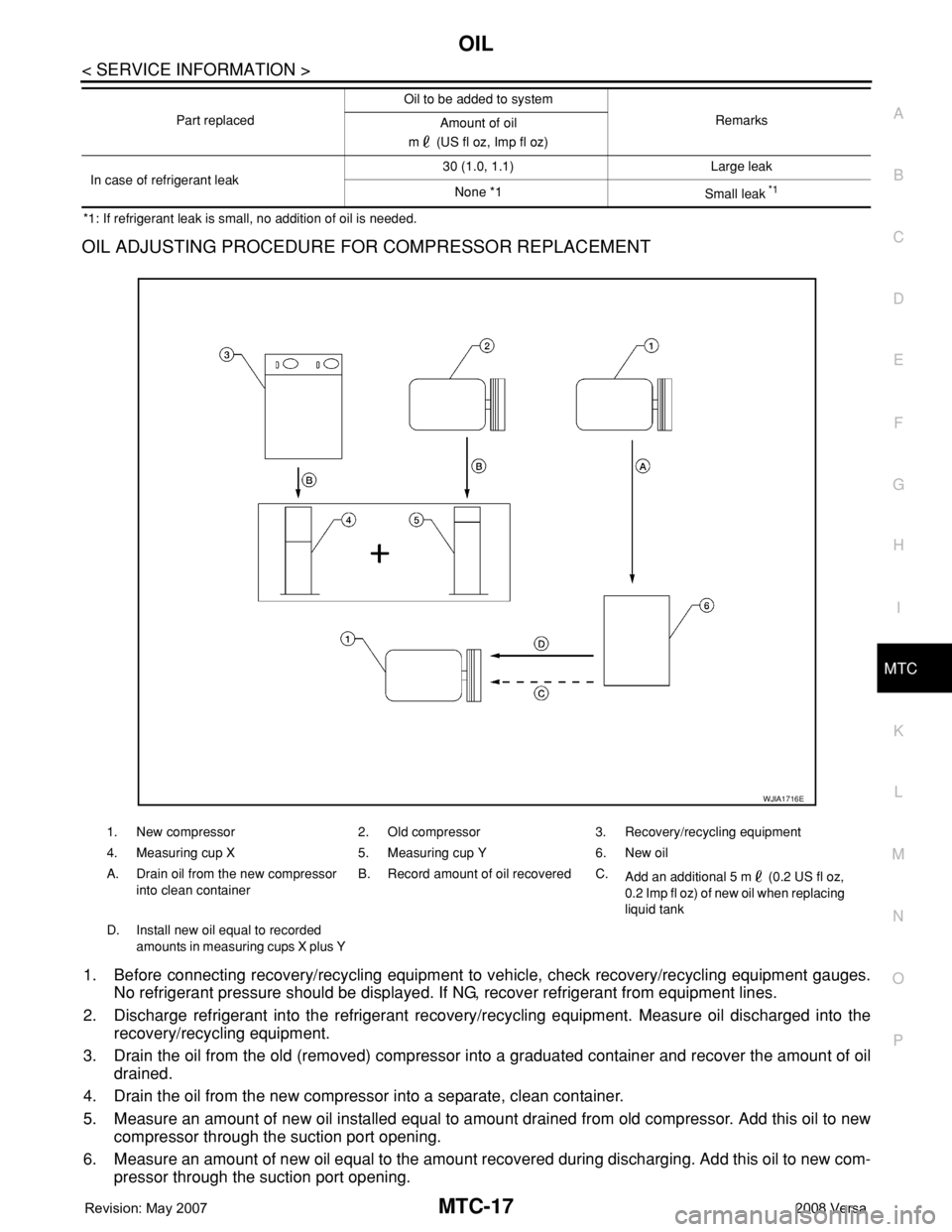
OIL ADJUSTING PROCEDURE FOR COMPRESSOR REPLACEMENT
1. Before connecting recovery/recycling equipment to vehicle, check recovery/recycling equipment gauges.
No refrigerant pressure should be displayed. If NG, recover refrigerant from equipment lines.
2. Discharge refrigerant into the refrigerant recovery/recycling equipment. Measure oil discharged into the
recovery/recycling equipment.
3. Drain the oil from the old (removed) compressor into a graduated container and recover the amount of oil
drained.
4. Drain the oil from the new compressor into a separate, clean container.
5. Measure an amount of new oil installed equal to amount drained from old compressor. Add this oil to new
compressor through the suction port opening.
6. Measure an amount of new oil equal to the amount recovered during discharging. Add this oil to new com-
pressor through the suction port opening.
In case of refrigerant leak30 (1.0, 1.1) Large leak
None *1
Small leak *1
Part replacedOil to be added to system
Remarks
Amount of oil
m (US fl oz, Imp fl oz)
1. New compressor 2. Old compressor 3. Recovery/recycling equipment
4. Measuring cup X 5. Measuring cup Y 6. New oil
A. Drain oil from the new compressor
into clean containerB. Record amount of oil recovered C.
Add an additional 5 m (0.2 US fl oz,
0.2 Imp fl oz) of new oil when replacing
liquid tank
D. Install new oil equal to recorded
amounts in measuring cups X plus Y
WJIA1716E
Page 2388 of 2771
MTC-50
< SERVICE INFORMATION >
TROUBLE DIAGNOSIS
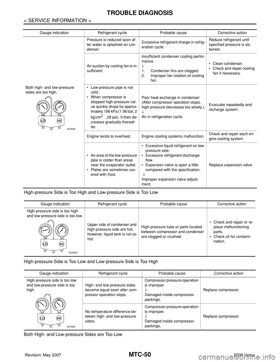
High-pressure Side is Too High and Low-pressure Side is Too Low
High-pressure Side is Too Low and Low-pressure Side is Too High
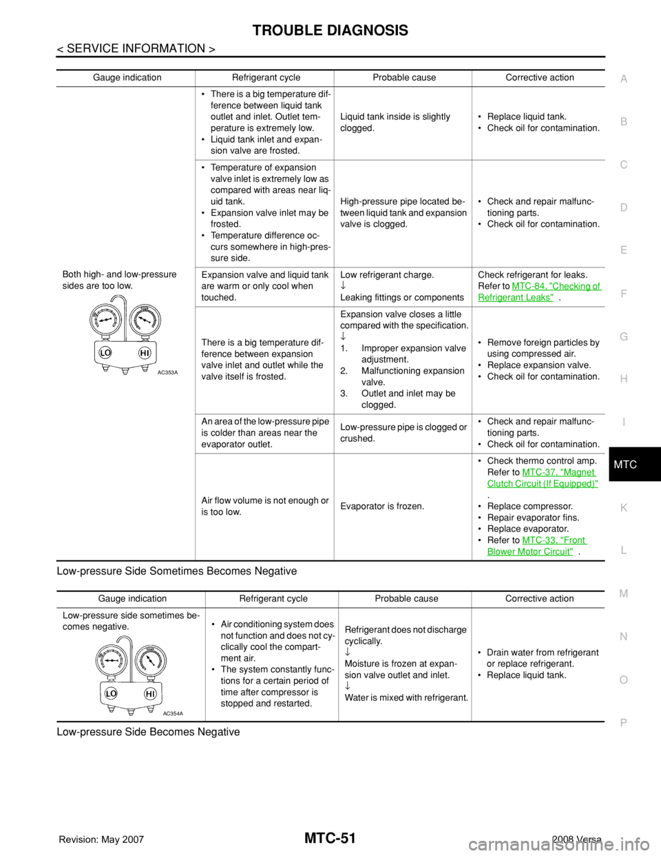
Both High- and Low-pressure Sides are Too Low
Gauge indication Refrigerant cycle Probable cause Corrective action
Both high- and low-pressure
sides are too high.Pressure is reduced soon af-
ter water is splashed on con-
denser.Excessive refrigerant charge in refrig-
eration cycle.Reduce refrigerant until
specified pressure is ob-
tained.
Air suction by cooling fan is in-
sufficient.Insufficient condenser cooling perfor-
mance.
↓
1. Condenser fins are clogged.
2. Improper fan rotation of cooling
fan.• Clean condenser.
• Check and repair cooling
fan if necessary.
• Low-pressure pipe is not
cold.
• When compressor is
stopped high-pressure val-
ue quickly drops by approx-
imately 196 kPa (1.96 bar, 2
kg/cm
2 , 28 psi). It then de-
creases gradually thereaf-
ter.Poor heat exchange in condenser
(After compressor operation stops,
high-pressure decreases too slowly.).
↓
Air in refrigeration cycle.Evacuate repeatedly and
recharge system.
Engine tends to overheat. Engine cooling systems malfunction.Check and repair each en-
gine cooling system.
• An area of the low-pressure
pipe is colder than areas
near the evaporator outlet.
• Plates are sometimes cov-
ered with frost.• Excessive liquid refrigerant on low-
pressure side.
• Excessive refrigerant discharge
flow.
• Expansion valve is open a little
compared with the specification.
↓
Improper expansion valve adjust-
ment.Replace expansion valve.
AC359A
Gauge indication Refrigerant cycle Probable cause Corrective action
High-pressure side is too high
and low-pressure side is too low.
Upper side of condenser and
high-pressure side are hot,
however, liquid tank is not so
hot.High-pressure tube or parts located
between compressor and condenser
are clogged or crushed.• Check and repair or re-
place malfunctioning
parts.
• Check oil for contami-
nation.
AC360A
Gauge indication Refrigerant cycle Probable cause Corrective action
High-pressure side is too low
and low-pressure side is too
high.High- and low-pressure sides
become equal soon after com-
pressor operation stops.Compressor pressure operation
is improper.
↓
Damaged inside compressor
packings.Replace compressor.
No temperature difference be-
tween high- and low-pressure
sides.Compressor pressure operation
is improper.
↓
Damaged inside compressor
packings.Replace compressor.
AC356A
Page 2389 of 2771
TROUBLE DIAGNOSIS
MTC-51
< SERVICE INFORMATION >
C
D
E
F
G
H
I
K
L
MA
B
MTC
N
O
P Low-pressure Side Sometimes Becomes Negative
Low-pressure Side Becomes Negative
Gauge indication Refrigerant cycle Probable cause Corrective action
Both high- and low-pressure
sides are too low.• There is a big temperature dif-
ference between liquid tank
outlet and inlet. Outlet tem-
perature is extremely low.
• Liquid tank inlet and expan-
sion valve are frosted.Liquid tank inside is slightly
clogged.• Replace liquid tank.
• Check oil for contamination.
• Temperature of expansion
valve inlet is extremely low as
compared with areas near liq-
uid tank.
• Expansion valve inlet may be
frosted.
• Temperature difference oc-
curs somewhere in high-pres-
sure side.High-pressure pipe located be-
tween liquid tank and expansion
valve is clogged.• Check and repair malfunc-
tioning parts.
• Check oil for contamination.
Expansion valve and liquid tank
are warm or only cool when
touched.Low refrigerant charge.
↓
Leaking fittings or componentsCheck refrigerant for leaks.
Refer to MTC-84, "
Checking of
Refrigerant Leaks" .
There is a big temperature dif-
ference between expansion
valve inlet and outlet while the
valve itself is frosted.Expansion valve closes a little
compared with the specification.
↓
1. Improper expansion valve
adjustment.
2. Malfunctioning expansion
valve.
3. Outlet and inlet may be
clogged.• Remove foreign particles by
using compressed air.
• Replace expansion valve.
• Check oil for contamination.
An area of the low-pressure pipe
is colder than areas near the
evaporator outlet.Low-pressure pipe is clogged or
crushed.• Check and repair malfunc-
tioning parts.
• Check oil for contamination.
Air flow volume is not enough or
is too low.Evaporator is frozen.• Check thermo control amp.
Refer to MTC-37, "
Magnet
Clutch Circuit (If Equipped)"
.
• Replace compressor.
• Repair evaporator fins.
• Replace evaporator.
• Refer to MTC-33, "
Front
Blower Motor Circuit" .
AC353A
Gauge indication Refrigerant cycle Probable cause Corrective action
Low-pressure side sometimes be-
comes negative.• Air conditioning system does
not function and does not cy-
clically cool the compart-
ment air.
• The system constantly func-
tions for a certain period of
time after compressor is
stopped and restarted.Refrigerant does not discharge
cyclically.
↓
Moisture is frozen at expan-
sion valve outlet and inlet.
↓
Water is mixed with refrigerant.• Drain water from refrigerant
or replace refrigerant.
• Replace liquid tank.
AC354A
Page 2390 of 2771
MTC-52
< SERVICE INFORMATION >
TROUBLE DIAGNOSIS
Insufficient Heating
INFOID:0000000001704307
SYMPTOM: Insufficient heating
INSPECTION FLOW
1.CONFIRM SYMPTOM BY PERFORMING OPERATIONAL CHECK - TEMPERATURE DECREASE
1. Turn temperature control dial clockwise to maximum heat position.
2. Check for hot air at discharge air outlets.
Can the symptom be duplicated?
YES >> GO TO 3.
NO >> GO TO 2.
2.CHECK FOR ANY SYMPTOMS
Perform a complete operational check for any symptoms. Refer to MTC-30, "
Operational Check" .
Does another symptom exist?
YES >> Refer to MTC-22, "How to Perform Trouble Diagnosis for Quick and Accurate Repair" .
NO >> System OK.
3.CHECK FOR SERVICE BULLETINS
Check for any service bulletins.
>> GO TO 4.
4.CHECK COOLANT SYSTEM
1. Check engine coolant level. Refer to CO-8
.
2. Check hoses for leaks or kinks.
3. Check Radiator cap. Refer to CO-13, "
Checking Radiator Cap" .
OK or NG
OK >> GO TO 5.
NG >> Repair/replace as necessary.
5.CHECK AIR MIX DOOR CABLE
Check air mix door cable operation. Refer to MTC-64, "
Air Mix Door Cable Adjustment" .
OK or NG
YES >> GO TO 6.
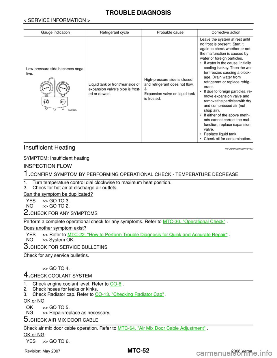
Gauge indication Refrigerant cycle Probable cause Corrective action
Low-pressure side becomes nega-
tive.
Liquid tank or front/rear side of
expansion valve’s pipe is frost-
ed or dewed.High-pressure side is closed
and refrigerant does not flow.
↓
Expansion valve or liquid tank
is frosted.Leave the system at rest until
no frost is present. Start it
again to check whether or not
the malfunction is caused by
water or foreign particles.
• If water is the cause, initially
cooling is okay. Then the wa-
ter freezes causing a block-
age. Drain water from
refrigerant or replace refrig-
erant.
• If due to foreign particles, re-
move expansion valve and
remove the particles with dry
and compressed air (not
shop air).
• If either of the above meth-
ods cannot correct the mal-
function, replace expansion
valve.
• Replace liquid tank.
• Check oil for contamination.
AC362A
Page 2417 of 2771
REFRIGERANT LINES
MTC-79
< SERVICE INFORMATION >
C
D
E
F
G
H
I
K
L
MA
B
MTC
N
O
P
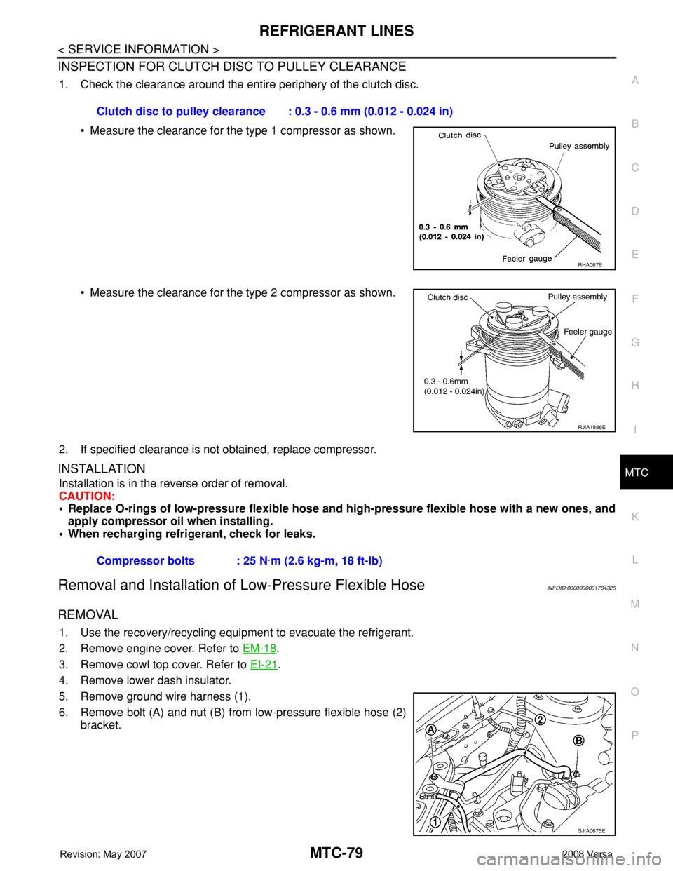
INSPECTION FOR CLUTCH DISC TO PULLEY CLEARANCE
1. Check the clearance around the entire periphery of the clutch disc.
• Measure the clearance for the type 1 compressor as shown.
• Measure the clearance for the type 2 compressor as shown.
2. If specified clearance is not obtained, replace compressor.
INSTALLATION
Installation is in the reverse order of removal.
CAUTION:
• Replace O-rings of low-pressure flexible hose and high-pressure flexible hose with a new ones, and
apply compressor oil when installing.
• When recharging refrigerant, check for leaks.
Removal and Installation of Low-Pressure Flexible HoseINFOID:0000000001704325
REMOVAL
1. Use the recovery/recycling equipment to evacuate the refrigerant.
2. Remove engine cover. Refer to EM-18
.
3. Remove cowl top cover. Refer to EI-21
.
4. Remove lower dash insulator.
5. Remove ground wire harness (1).
6. Remove bolt (A) and nut (B) from low-pressure flexible hose (2)
bracket.Clutch disc to pulley clearance : 0.3 - 0.6 mm (0.012 - 0.024 in)
RHA087E
RJIA1886E
Compressor bolts : 25 N·m (2.6 kg-m, 18 ft-lb)
SJIA0675E
Page 2418 of 2771
MTC-80
< SERVICE INFORMATION >
REFRIGERANT LINES
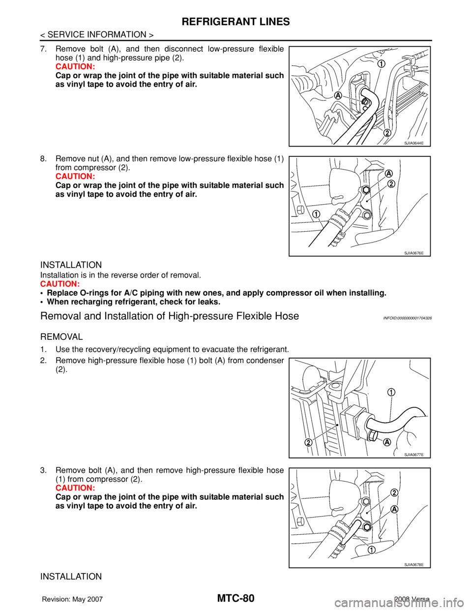
7. Remove bolt (A), and then disconnect low-pressure flexible
hose (1) and high-pressure pipe (2).
CAUTION:
Cap or wrap the joint of the pipe with suitable material such
as vinyl tape to avoid the entry of air.
8. Remove nut (A), and then remove low-pressure flexible hose (1)
from compressor (2).
CAUTION:
Cap or wrap the joint of the pipe with suitable material such
as vinyl tape to avoid the entry of air.
INSTALLATION
Installation is in the reverse order of removal.
CAUTION:
• Replace O-rings for A/C piping with new ones, and apply compressor oil when installing.
• When recharging refrigerant, check for leaks.
Removal and Installation of High-pressure Flexible HoseINFOID:0000000001704326
REMOVAL
1. Use the recovery/recycling equipment to evacuate the refrigerant.
2. Remove high-pressure flexible hose (1) bolt (A) from condenser
(2).
3. Remove bolt (A), and then remove high-pressure flexible hose
(1) from compressor (2).
CAUTION:
Cap or wrap the joint of the pipe with suitable material such
as vinyl tape to avoid the entry of air.
INSTALLATION
SJIA0644E
SJIA0676E
SJIA0677E
SJIA0678E
Page 2419 of 2771

REFRIGERANT LINES
MTC-81
< SERVICE INFORMATION >
C
D
E
F
G
H
I
K
L
MA
B
MTC
N
O
P
Installation is in the reverse order of removal.
CAUTION:
• Replace O-rings of high-pressure flexible hose with a new ones, and apply compressor oil when
installing.
• When recharging refrigerant, check for leaks.
Removal and Installation of High-pressure PipeINFOID:0000000001704327
REMOVAL
1. Remove low-pressure flexible hose. Refer to MTC-79, "Removal and Installation of Low-Pressure Flexible
Hose".
2. Remove high-pressure pipe from the clips.
3. Remove high-pressure pipe bolt (A), and then remove high-
pressure pipe (1) from condenser (2).
CAUTION:
Cap or wrap the joint of the pipe with suitable material such
as vinyl tape to avoid the entry of air.
INSTALLATION
Installation is in the reverse order of removal.
CAUTION:
• Replace O-rings of high-pressure pipe with a new ones, and apply compressor oil when installing.
• When recharging refrigerant, check for leaks.
Removal and Installation of Refrigerant Pressure SensorINFOID:0000000001704328
REMOVAL
1. Use the recovery/recycling equipment to evacuate the refrigerant.
2. Disconnect connector, and then remove refrigerant pressure
sensor (1) from condenser (2).
CAUTION:
When working, be careful not to damage the condenser
fins.
1. High-pressure pipe A. High-pressure pipe clips
SJIA0679E
SJIA0680E
SJIA0681E
Page 2420 of 2771
MTC-82
< SERVICE INFORMATION >
REFRIGERANT LINES
INSTALLATION
Installation is in the reverse order of removal.
CAUTION:
• Replace O-rings of refrigerant pressure sensor with a new one, and apply compressor oil when
installing.
• When recharging refrigerant, check for leaks.
Removal and Installation of CondenserINFOID:0000000001704329
REMOVAL
1. Remove the three upper headlamp bolts to reposition the headlamps out of the way
2. Remove the radiator core support upper. Refer to BL-19
.
3. Remove high-pressure flexible hose and high-pressure pipe from condenser. Refer to MTC-80, "
Removal
and Installation of High-pressure Flexible Hose" and MTC-81, "Removal and Installation of High-pres-
sure Pipe" .
CAUTION:
Cap or wrap the joint of the pipe with suitable material such as vinyl tape to avoid the entry of air.
4. Disconnect refrigerant pressure sensor connector.
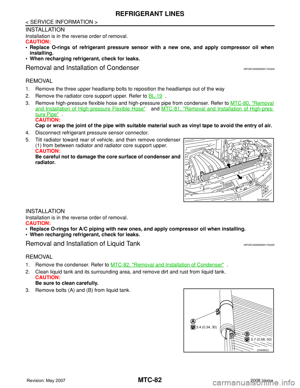
5. Tilt radiator toward rear of vehicle, and then remove condenser
(1) from between radiator and radiator core support upper.
CAUTION:
Be careful not to damage the core surface of condenser and
radiator.
INSTALLATION
Installation is in the reverse order of removal.
CAUTION:
• Replace O-rings for A/C piping with new ones, and apply compressor oil when installing.
• When recharging refrigerant, check for leaks.
Removal and Installation of Liquid TankINFOID:0000000001704330
REMOVAL
1. Remove the condenser. Refer to MTC-82, "Removal and Installation of Condenser" .
2. Clean liquid tank and its surrounding area, and remove dirt and rust from liquid tank.
CAUTION:
Be sure to clean carefully.
3. Remove bolts (A) and (B) from liquid tank.
SJIA0682E
ZJIA0842J