CAN communication error NISSAN TIIDA 2008 Service Repair Manual
[x] Cancel search | Manufacturer: NISSAN, Model Year: 2008, Model line: TIIDA, Model: NISSAN TIIDA 2008Pages: 2771, PDF Size: 60.61 MB
Page 40 of 2771
AT-28
< SERVICE INFORMATION >
A/T CONTROL SYSTEM
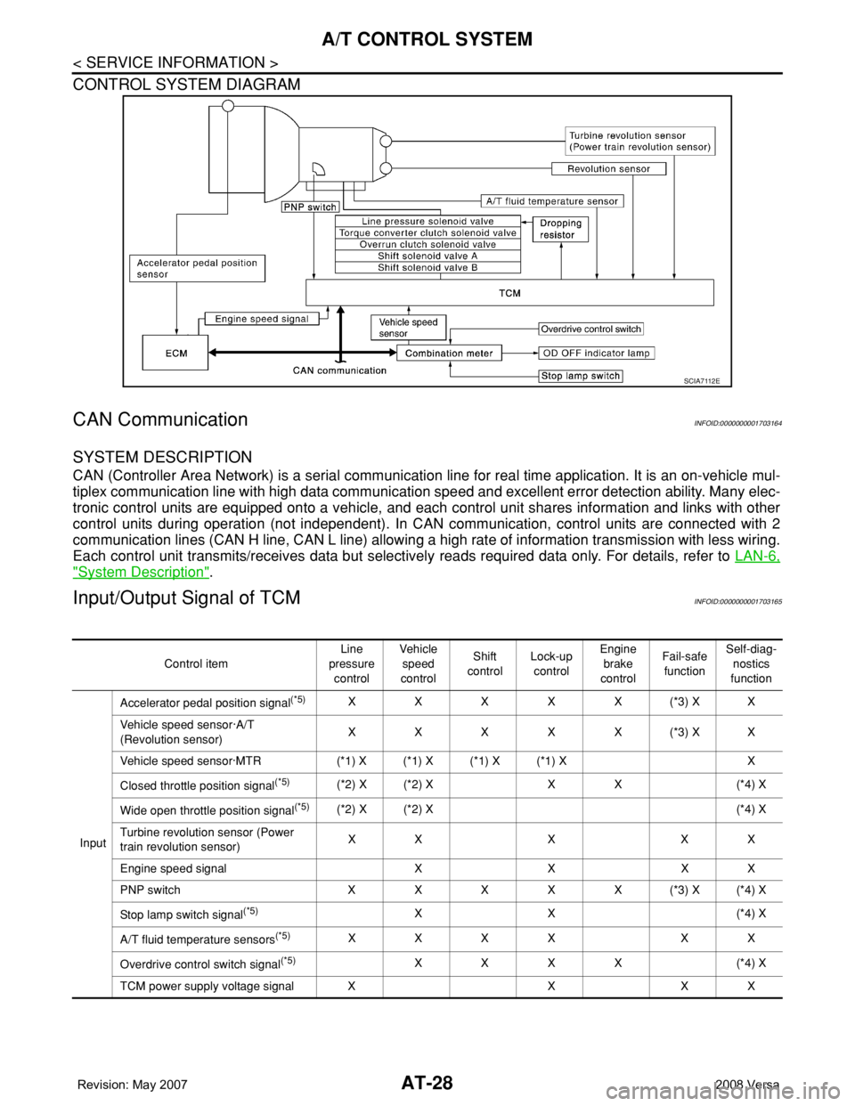
CONTROL SYSTEM DIAGRAM
CAN CommunicationINFOID:0000000001703164
SYSTEM DESCRIPTION
CAN (Controller Area Network) is a serial communication line for real time application. It is an on-vehicle mul-
tiplex communication line with high data communication speed and excellent error detection ability. Many elec-
tronic control units are equipped onto a vehicle, and each control unit shares information and links with other
control units during operation (not independent). In CAN communication, control units are connected with 2
communication lines (CAN H line, CAN L line) allowing a high rate of information transmission with less wiring.
Each control unit transmits/receives data but selectively reads required data only. For details, refer to LAN-6,
"System Description".
Input/Output Signal of TCMINFOID:0000000001703165
SCIA7112E
Control itemLine
pressure
controlVehicle
speed
controlShift
controlLock-up
controlEngine
brake
controlFail-safe
functionSelf-diag-
nostics
function
InputAccelerator pedal position signal
(*5)XXXXX(*3) XX
Vehicle speed sensor·A/T
(Revolution sensor)XXXXX(*3) XX
Vehicle speed sensor·MTR (*1) X (*1) X (*1) X (*1) X X
Closed throttle position signal
(*5)(*2) X (*2) X X X (*4) X
Wide open throttle position signal
(*5)(*2) X (*2) X (*4) X
Turbine revolution sensor (Power
train revolution sensor)XXXXX
Engine speed signal X X X X
PNP switch XXXXX(*3) X(*4) X
Stop lamp switch signal
(*5)XX (*4) X
A/T fluid temperature sensors
(*5)XXXX XX
Overdrive control switch signal
(*5)XXXX (*4) X
TCM power supply voltage signal X X X X
Page 41 of 2771
A/T CONTROL SYSTEM
AT-29
< SERVICE INFORMATION >
D
E
F
G
H
I
J
K
L
MA
B
AT
N
O
P
*1: Spare for vehicle speed sensor·A/T (revolution sensor)
*2: Spare for accelerator pedal position signal
*3: If these input and output signals are different, the TCM triggers the fail-safe function.
*4: Used as a condition for starting self-diagnostics; if self-diagnosis are not started, it is judged that there is some kind of error.
*5: Input by CAN communications.
*6: Output by CAN communications.
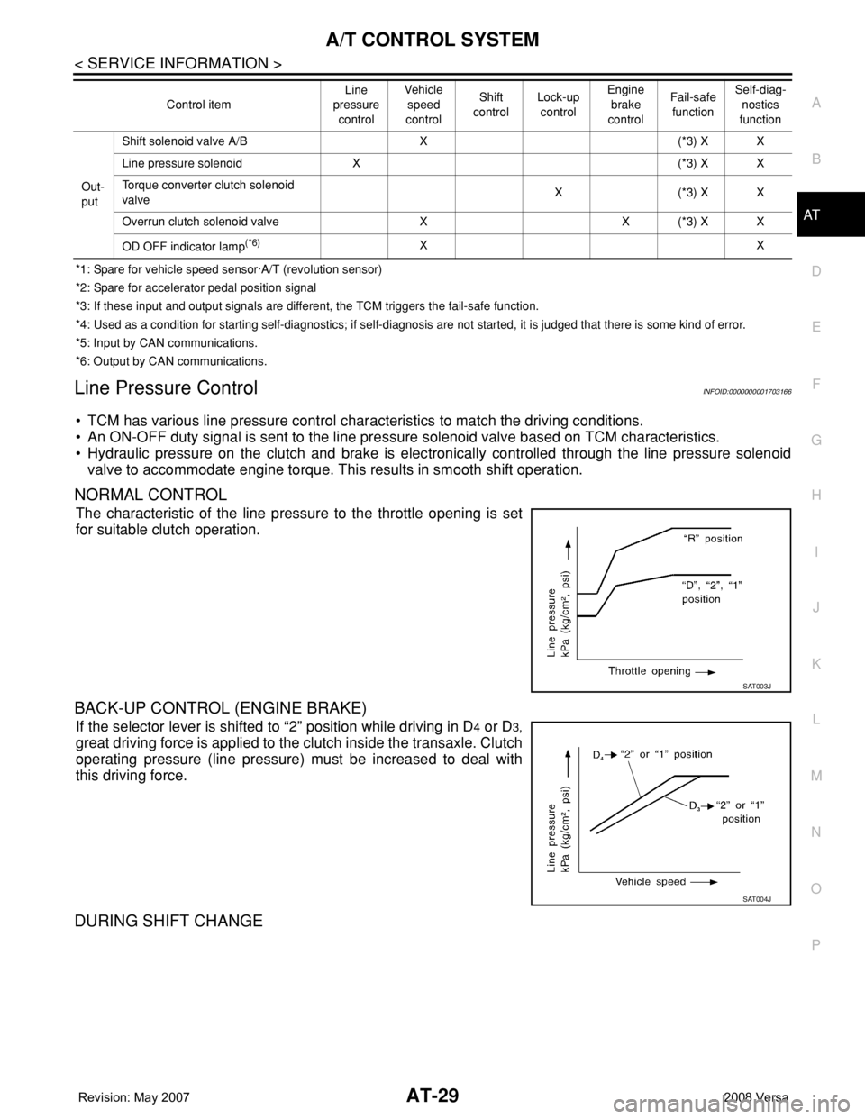
Line Pressure ControlINFOID:0000000001703166
• TCM has various line pressure control characteristics to match the driving conditions.
• An ON-OFF duty signal is sent to the line pressure solenoid valve based on TCM characteristics.
• Hydraulic pressure on the clutch and brake is electronically controlled through the line pressure solenoid
valve to accommodate engine torque. This results in smooth shift operation.
NORMAL CONTROL
The characteristic of the line pressure to the throttle opening is set
for suitable clutch operation.
BACK-UP CONTROL (ENGINE BRAKE)
If the selector lever is shifted to “2” position while driving in D4 or D3,
great driving force is applied to the clutch inside the transaxle. Clutch
operating pressure (line pressure) must be increased to deal with
this driving force.
DURING SHIFT CHANGE
Out-
putShift solenoid valve A/B X (*3) X X
Line pressure solenoid X (*3) X X
Torque converter clutch solenoid
valveX(*3) XX
Overrun clutch solenoid valve X X (*3) X X
OD OFF indicator lamp
(*6)XX Control itemLine
pressure
controlVeh icl e
speed
controlShift
controlLock-up
controlEngine
brake
controlFail-safe
functionSelf-diag-
nostics
function
SAT003J
SAT004J
Page 782 of 2771
![NISSAN TIIDA 2008 Service Repair Manual TROUBLE DIAGNOSIS
BRC-17
< SERVICE INFORMATION >[ABS]
C
D
E
G
H
I
J
K
L
MA
B
BRC
N
O
P
• If ABS actuator and electric unit (control unit) connection is loose, tighten the piping to the specified
tor](/img/5/57399/w960_57399-781.png "NISSAN TIIDA 2008 Service Repair Manual TROUBLE DIAGNOSIS
BRC-17
< SERVICE INFORMATION >[ABS]
C
D
E
G
H
I
J
K
L
MA
B
BRC
N
O
P
• If ABS actuator and electric unit (control unit) connection is loose, tighten the piping to the specified
tor")
TROUBLE DIAGNOSIS
BRC-17
< SERVICE INFORMATION >[ABS]
C
D
E
G
H
I
J
K
L
MA
B
BRC
N
O
P
• If ABS actuator and electric unit (control unit) connection is loose, tighten the piping to the specified
torque and recheck for leaks.
• If there is damage to the connection flare nut or ABS actuator and electric unit (control unit) threads,
replace the damaged part and recheck for leaks.
• When there is fluid leaking or seeping from a fluid connection, use a clean cloth to wipe off the fluid and
recheck for leaks. If fluid is still seeping out, replace the damaged part. If the fluid is leaking at the ABS
actuator and electric unit (control unit), replace the ABS actuator and electric unit (control unit) assem-
bly.
CAUTION:
The ABS actuator and electric unit (control unit) cannot be disassembled and must be replaced
as an assembly.
3. Check the brake pads for excessive wear.
POWER SYSTEM TERMINAL LOOSENESS AND BATTERY INSPECTION
Make sure the battery positive cable, negative cable and ground connection are not loose. In addition, make
sure the battery is sufficiently charged.
ABS WARNING LAMP INSPECTION
1. Make sure ABS warning lamp turns on for approximately 2 seconds when the ignition switch is turned ON.
If it does not, check CAN communications. If there are no errors with the CAN communication system,
replace the combination meter. Refer to IP-11, "
Removal and Installation".
2. Make sure the lamp turns off approximately 2 seconds after the ignition switch is turned ON. If the lamp
does not turn off, conduct self-diagnosis of ABS actuator and electric unit (control unit). If no malfunctions
are detected in self-diagnosis, replace combination meter. Refer to IP-11, "
Removal and Installation".
3. After conducting the self-diagnosis, be sure to erase the error memory. Refer to BRC-18, "
CONSULT-III
Function (ABS)".
Warning Lamp and Indicator TimingINFOID:0000000001703836
Note 1: Brake warning lamp will turn on when the parking brake is applied or when the brake fluid level is low.
x: ON
–: OFF
Control Unit Input/Output Signal StandardINFOID:0000000001703837
REFERENCE VALUE FROM CONSULT-III
CAUTION:
The display shows the control unit calculation data, so a normal value might be displayed even in the
event the output circuit (harness) is open or short circuited.
ConditionABS
warning lampBRAKE
warning lamp
[Note 1]Remarks
When the ignition switch is OFF – – –
After the ignition switch is turned ON for approx. 1
second××–
After the ignition switch is turned ON for approx. 2
seconds––Lamp goes off approx. 2 seconds after the
engine is started.
ABS malfunction×––
EBD malfunction××–
Page 783 of 2771
![NISSAN TIIDA 2008 Service Repair Manual BRC-18
< SERVICE INFORMATION >[ABS]
TROUBLE DIAGNOSIS
Note 1: Confirm tire pressure is normal.
Note 2: ON/OFF timing of ABS warning lamp
ON: For approximately 2 seconds after ignition switch is turned](/img/5/57399/w960_57399-782.png "NISSAN TIIDA 2008 Service Repair Manual BRC-18
< SERVICE INFORMATION >[ABS]
TROUBLE DIAGNOSIS
Note 1: Confirm tire pressure is normal.
Note 2: ON/OFF timing of ABS warning lamp
ON: For approximately 2 seconds after ignition switch is turned")
BRC-18
< SERVICE INFORMATION >[ABS]
TROUBLE DIAGNOSIS
Note 1: Confirm tire pressure is normal.
Note 2: ON/OFF timing of ABS warning lamp
ON: For approximately 2 seconds after ignition switch is turned ON, or when a malfunction is detected.
OFF: Approximately 2 seconds after ignition switch is turned ON (when system is in normal operation).
CONSULT-III Function (ABS)INFOID:0000000001703838
CONSULT-III can display each diagnostic item using the diagnostic test modes shown following.
Monitor item Display contentData monitor
Note: Error inspection
checklist
ConditionReference value in
normal operation
FR RH SENSOR
FR LH SENSOR
RR RH SENSOR
RR LH SENSORWheel speedVehicle stopped 0 [km/h (MPH)]
BRC-24, "
Wheel Sensor
System"Vehicle running (Note 1)Almost in accor-
dance with speed-
ometer display
(within ±10%)
BATTERY VOLTBattery voltage sup-
plied to ABS actuator
and electric unit (con-
trol unit)Ignition switch ON 10 to 16VBRC-27, "
ABS Control
Unit Power and Ground
Systems Inspection"
STOP LAMP SWStop lamp switch oper-
ationBrake pedal depressed ON
—
Brake pedal not depressed OFF
ABS WARN LAMPABS warning lamp ON
condition (Note 2)ABS warning lamp ON ON
BRC-16, "
Basic Inspec-
tion"ABS warning lamp OFF OFF
MOTOR RELAYOperation status of mo-
tor and motor relayIgnition switch ON or running
(ABS not activated)OFF
BRC-26, "
Actuator Motor,
Motor Relay, and Circuit
Inspection"Ignition switch ON or engine
running (ABS activated)ON
ACTUATOR RLYActuator relay opera-
tion statusVehicle stopped (Ignition
switch ON)OFF
BRC-26, "
Actuator Motor,
Motor Relay, and Circuit
Inspection"Vehicle stopped (Engine run-
ning)ON
FR LH IN SOL
FR LH OUT SOL
FR RH IN SOL
FR RH OUT SOL
RR RH IN SOL
RR RH OUT SOL
RR LH IN SOL
RR LH OUT SOLSolenoid valve opera-
tionActuator (solenoid) is active
(“ACTIVE TEST” with CON-
SULT-III) or actuator relay is in-
active (in fail-safe mode).ON
BRC-25, "
Solenoid Valve
System Inspection"When actuator (solenoid) is not
active and actuator relay is ac-
tive (ignition switch ON).OFF
ABS SIGNAL
EBD SIGNALSignal statusABS active
EBD activeON
ABS system
EBD system
ABS not active
EBD not activeOFF
ABS FAIL SIG
EBD FAIL SIGFail signal statusABS fail
EBD failON
ABS system
EBD system
ABS normal
EBD normalOFF
ABS diagnostic mode Description
SELF-DIAG RESULTS Displays ABS actuator and electric unit (control unit) self-diagnosis results.
DATA MONITOR Displays ABS actuator and electric unit (control unit) input/output data in real time.
CAN DIAG SUPPORT MNTR The result of transmit/receive diagnosis of CAN communication can be read.
ACTIVE TEST Operation of electrical loads can be checked by sending drive signal to them.
Page 860 of 2771
CVT SYSTEM
CVT-21
< SERVICE INFORMATION >
D
E
F
G
H
I
J
K
L
MA
B
CVT
N
O
P
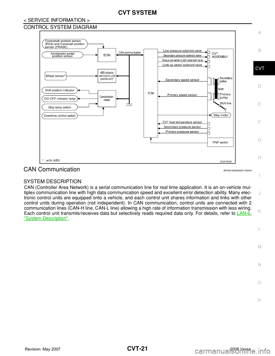
CONTROL SYSTEM DIAGRAM
CAN CommunicationINFOID:0000000001703440
SYSTEM DESCRIPTION
CAN (Controller Area Network) is a serial communication line for real time application. It is an on-vehicle mul-
tiplex communication line with high data communication speed and excellent error detection ability. Many elec-
tronic control units are equipped onto a vehicle, and each control unit shares information and links with other
control units during operation (not independent). In CAN communication, control units are connected with 2
communication lines (CAN-H line, CAN-L line) allowing a high rate of information transmission with less wiring.
Each control unit transmits/receives data but selectively reads required data only. For details, refer to LAN-6,
"System Description".
SCIA7933E
Page 868 of 2771

TROUBLE DIAGNOSIS
CVT-29
< SERVICE INFORMATION >
D
E
F
G
H
I
J
K
L
MA
B
CVT
N
O
P
TROUBLE DIAGNOSIS
DTC Inspection Priority ChartINFOID:0000000001703451
If some DTCs are displayed at the same time, perform inspections one by one based on the following priority
chart.
NOTE:
If DTC “U1000 CAN COMM CIRCUIT” is displayed with other DTCs, first perform the trouble diagnosis
for “DTC U1000 CAN COMMUNICATION LINE”. Refer to CVT-56
.
Fail-SafeINFOID:0000000001703452
The TCM has an electrical fail-safe mode. This mode makes it possible to operate even if there is an error in a
main electronic control input/output signal circuit.
FAIL-SAFE FUNCTION
If any malfunction occurs in a sensor or solenoid, this function controls the CVT to make driving possible.
Output Speed Sensor (Secondary Speed Sensor)
The shift pattern is changed in accordance with throttle position when an unexpected signal is sent from the
output speed sensor (secondary speed sensor) to the TCM. The overdrive-off mode is inhibited, and the tran-
saxle is put in “D”.
Input Speed Sensor (Primary Speed Sensor)
The shift pattern is changed in accordance with throttle position and secondary speed (vehicle speed) when
an unexpected signal is sent from the input speed sensor (primary speed sensor) to the TCM. The sport mode
is inhibited, and the transaxle is put in “D”.
PNP Switch
If an unexpected signal is sent from the PNP switch to the TCM, the transaxle is put in “D”.
CVT Fluid Temperature Sensor
If an unexpected signal is sent from the CVT fluid temperature sensor to the TCM, the gear ratio in use before
receiving the unexpected signal is maintained or the gear ratio is controlled to keep engine speed under 3500
rpm.
Transmission Fluid Pressure Sensor A (Secondary Pressure Sensor)
• If an unexpected signal is sent from the transmission fluid pressure sensor A (secondary pressure sensor) to
the TCM, the secondary pressure feedback control is stopped and the offset value obtained before the non-
standard condition occurs is used to control line pressure.
• If transmission fluid pressure sensor A (secondary pressure sensor) error signal is input to TCM, secondary
pressure feedback control stops, but line pressure is controlled normally.
Pressure Control Solenoid A (Line Pressure Solenoid)
If an unexpected signal is sent from the solenoid to the TCM, the pressure control solenoid A (line pressure
solenoid) is turned OFF to achieve the maximum fluid pressure.
Pressure Control Solenoid B (Secondary Pressure Solenoid)
If an unexpected signal is sent from the solenoid to the TCM, the pressure control solenoid B (secondary pres-
sure solenoid) is turned OFF to achieve the maximum fluid pressure.
Torque Converter Clutch Solenoid
If an unexpected signal is sent from the solenoid to the TCM, the torque converter clutch solenoid is turned
OFF to cancel the lock-up.
Ste p M oto r
If an unexpected signal is sent from the step motor to the TCM, the step motor coil phases “A” through “D” are
all turned OFF to hold the gear ratio used right before the non-standard condition occurred.
CVT Lock-up Select Solenoid
Priority Detected items (DTC)
1 U1000 CAN communication line
2 Except above
Page 1104 of 2771

EC-30
< SERVICE INFORMATION >
CAN COMMUNICATION
CAN COMMUNICATION
System DescriptionINFOID:0000000001702562
CAN (Controller Area Network) is a serial communication line for real time application. It is an on-vehicle mul-
tiplex communication line with high data communication speed and excellent error detection ability. Many elec-
tronic control units are equipped onto a vehicle, and each control unit shares information and links with other
control units during operation (not independent). In CAN communication, control units are connected with 2
communication lines (CAN H line, CAN L line) allowing a high rate of information transmission with less wiring.
Each control unit transmits/receives data but selectively reads required data only.
Refer to LAN-23, "
CAN System Specification Chart", about CAN communication for detail.
Page 1217 of 2771
DTC U1000, U1001 CAN COMMUNICATION LINE
EC-143
< SERVICE INFORMATION >
C
D
E
F
G
H
I
J
K
L
MA
EC
N
P O
DTC U1000, U1001 CAN COMMUNICATION LINE
DescriptionINFOID:0000000001702608
CAN (Controller Area Network) is a serial communication line for real time application. It is an on-vehicle mul-
tiplex communication line with high data communication speed and excellent error detection ability. Many elec-
tronic control units are equipped onto a vehicle, and each control unit shares information and links with other
control units during operation (not independent). In CAN communication, control units are connected with 2
communication lines (CAN H line, CAN L line) allowing a high rate of information transmission with less wiring.
Each control unit transmits/receives data but selectively reads required data only.
On Board Diagnosis LogicINFOID:0000000001702609
*1: This self-diagnosis has the one trip detection logic (A/T, CVT).
The MIL will not light up for this self-diagnosis (M/T).
*2: The MIL will not light up for this self-diagnosis.
DTC Confirmation ProcedureINFOID:0000000001702610
1. Turn ignition switch ON and wait at least 3 seconds.
2. Select “DATA MONITOR” mode with CONSULT-II.
3. If 1st trip DTC is detected, go to EC-144, "
Diagnosis Procedure".
DTC No.Trouble diagnosis
nameDTC detecting condition Possible cause
U1000*
1
1000*1CAN communication
lineWhen ECM is not transmitting or receiving CAN
communication signal of OBD (emission related
diagnosis) for 2 seconds or more.• Harness or connectors
(CAN communication line is open or
shorted.)
U1001*
2
1001*2
When ECM is not transmitting or receiving CAN
communication signal other than OBD (emission-
related diagnosis) for 2 seconds or more.
Page 1219 of 2771
DTC U1010 CAN COMMUNICATION
EC-145
< SERVICE INFORMATION >
C
D
E
F
G
H
I
J
K
L
MA
EC
N
P O
DTC U1010 CAN COMMUNICATION
DescriptionINFOID:0000000001702613
CAN (Controller Area Network) is a serial communication line for real time application. It is an on-vehicle mul-
tiplex communication line with high data communication speed and excellent error detection ability. Many elec-
tronic control units are equipped onto a vehicle, and each control unit shares information and links with other
control units during operation (not independent). In CAN communication, control units are connected with 2
communication lines (CAN H line, CAN L line) allowing a high rate of information transmission with less wiring.
Each control unit transmits/receives data but selectively reads required data only.
On Board Diagnosis LogicINFOID:0000000001702614
This self-diagnosis has the one trip detection logic (A/T, CVT).
The MIL will not light up for this self-diagnosis (M/T).
DTC Confirmation ProcedureINFOID:0000000001702615
WITH CONSULT-II
1. Turn ignition switch ON.
2. Select “DATA MONITOR” mode with CONSULT-II.
3. If 1st trip DTC is detected, go to EC-145, "
Diagnosis Procedure".
WITH GST
Follow the procedure “WITH CONSULT-II” above.
Diagnosis ProcedureINFOID:0000000001702616
1.INSPECTION START
With CONSULT-II
1. Turn ignition switch ON.
2. Select “SELF-DIAG RESULTS” mode with CONSULT-II.
3. Touch “ERASE”.
4.Perform DTC Confirmation Procedure.
See EC-145, "
DTC Confirmation Procedure".
5. Is the 1st trip DTC U1010 displayed again?
With GST
1. Turn ignition switch ON.
2. Select Service $04 with GST.
3.Perform DTC Confirmation Procedure.
See EC-145, "
DTC Confirmation Procedure".
4. Is the 1st trip DTC U1010 displayed again?
Ye s o r N o
Yes >> GO TO 2.
No >>INSPECTION END
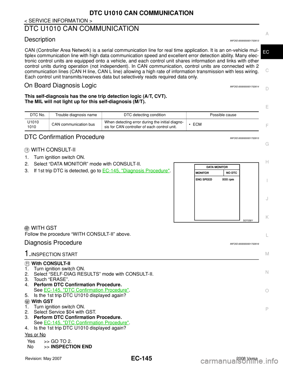
DTC No. Trouble diagnosis name DTC detecting condition Possible cause
U1010
1010CAN communication busWhen detecting error during the initial diagno-
sis for CAN controller of each control unit.•ECM
SEF058Y
Page 1992 of 2771

LAN-1
ELECTRICAL
C
D
E
F
G
H
I
J
L
M
SECTION LAN
A
B
LAN
N
O
P
CONTENTS
LAN SYSTEM
CAN FUNDAMENTAL
PRECAUTION ...............................................
5
PRECAUTIONS ...................................................5
Precautions for Trouble Diagnosis ............................5
Precautions for Harness Repair ................................5
FUNCTION DIAGNOSIS ...............................6
CAN COMMUNICATION SYSTEM .....................6
System Description ...................................................6
System Diagram ........................................................6
CAN Communication Control Circuit .........................7
DIAG ON CAN .....................................................8
Description ................................................................8
System Diagram ........................................................8
TROUBLE DIAGNOSIS ......................................9
Condition of Error Detection ......................................9
Symptom When Error Occurs in CAN Communi-
cation System ............................................................
9
CAN Diagnosis with CONSULT-III ..........................12
Self-Diagnosis .........................................................12
CAN Diagnostic Support Monitor ............................12
How to Use CAN Communication Signal Chart ......14
BASIC INSPECTION ...................................15
DIAGNOSIS AND REPAIR WORKFLOW .........15
Trouble Diagnosis Flow Chart .................................15
Trouble Diagnosis Procedure ..................................15
CAN
HOW TO USE THIS MANUAL .....................
20
HOW TO USE THIS SECTION ...........................20
Caution ....................................................................20
Abbreviation List ......................................................20
PRECAUTION ..............................................21
PRECAUTIONS .................................................21
Precaution for Supplemental Restraint System
(SRS) "AIR BAG" and "SEAT BELT PRE-TEN-
SIONER" .................................................................
21
Precautions for Trouble Diagnosis ..........................21
Precautions for Harness Repair ..............................21
BASIC INSPECTION ...................................22
DIAGNOSIS AND REPAIR WORKFLOW ........22
Interview Sheet ........................................................22
FUNCTION DIAGNOSIS ..............................23
CAN COMMUNICATION SYSTEM ...................23
CAN System Specification Chart .............................23
CAN Communication Signal Chart ..........................23
COMPONENT DIAGNOSIS .........................26
CAN COMMUNICATION SYSTEM ...................26
Component Parts Location ......................................26
Schematic ................................................................27
Wiring Diagram - CAN - ...........................................28
MALFUNCTION AREA CHART ........................30
Main Line .................................................................30
Branch Line .............................................................30
Short Circuit .............................................................30
MAIN LINE BETWEEN DLC AND ABS CIR-
CUIT ..................................................................
31
Diagnosis Procedure ...............................................31
MAIN LINE BETWEEN DLC AND TCM CIR-
CUIT ..................................................................
32
Diagnosis Procedure ...............................................32
ECM BRANCH LINE CIRCUIT .........................33
Diagnosis Procedure ...............................................33
BCM BRANCH LINE CIRCUIT .........................34
Diagnosis Procedure ...............................................34