combination meter fail NISSAN TIIDA 2008 Service Repair Manual
[x] Cancel search | Manufacturer: NISSAN, Model Year: 2008, Model line: TIIDA, Model: NISSAN TIIDA 2008Pages: 2771, PDF Size: 60.61 MB
Page 51 of 2771
TROUBLE DIAGNOSIS
AT-39
< SERVICE INFORMATION >
D
E
F
G
H
I
J
K
L
MA
B
AT
N
O
P
TROUBLE DIAGNOSIS
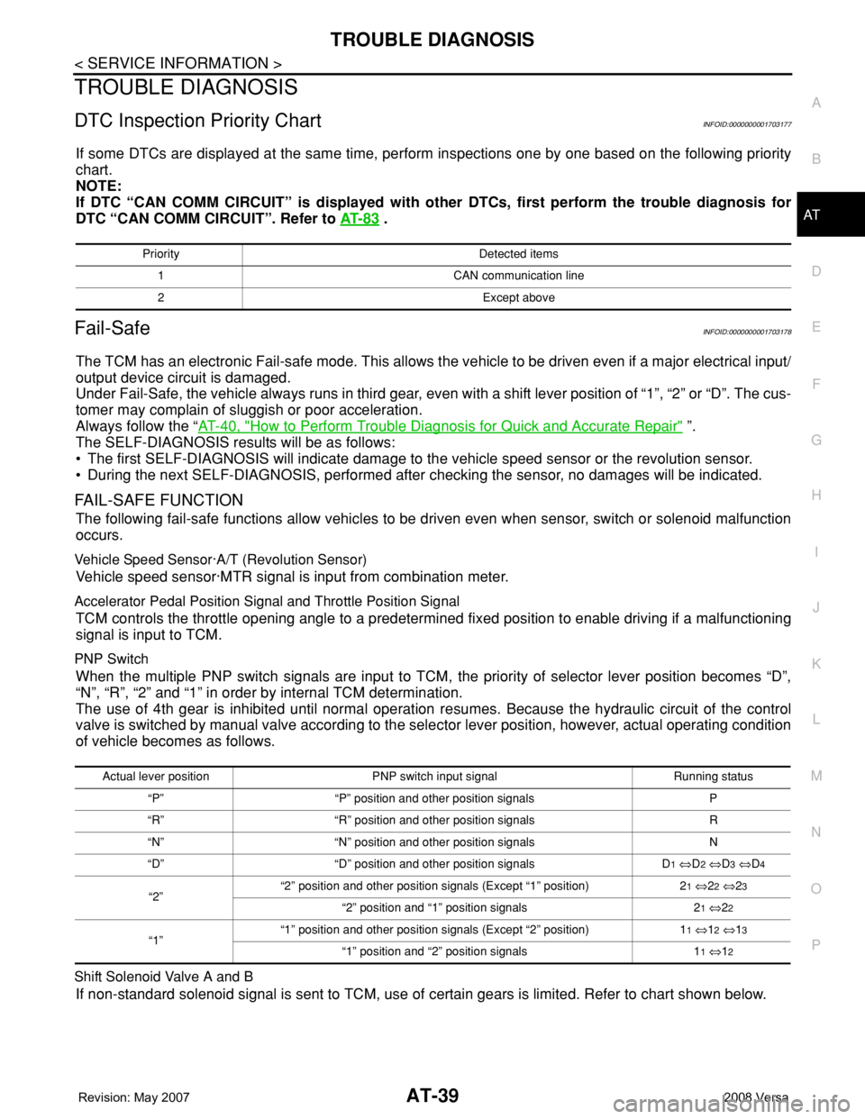
DTC Inspection Priority ChartINFOID:0000000001703177
If some DTCs are displayed at the same time, perform inspections one by one based on the following priority
chart.
NOTE:
If DTC “CAN COMM CIRCUIT” is displayed with other DTCs, first perform the trouble diagnosis for
DTC “CAN COMM CIRCUIT”. Refer to AT- 8 3
.
Fail-SafeINFOID:0000000001703178
The TCM has an electronic Fail-safe mode. This allows the vehicle to be driven even if a major electrical input/
output device circuit is damaged.
Under Fail-Safe, the vehicle always runs in third gear, even with a shift lever position of “1”, “2” or “D”. The cus-
tomer may complain of sluggish or poor acceleration.
Always follow the “AT-40, "
How to Perform Trouble Diagnosis for Quick and Accurate Repair" ”.
The SELF-DIAGNOSIS results will be as follows:
• The first SELF-DIAGNOSIS will indicate damage to the vehicle speed sensor or the revolution sensor.
• During the next SELF-DIAGNOSIS, performed after checking the sensor, no damages will be indicated.
FAIL-SAFE FUNCTION
The following fail-safe functions allow vehicles to be driven even when sensor, switch or solenoid malfunction
occurs.
Vehicle Speed Sensor·A/T (Revolution Sensor)
Vehicle speed sensor·MTR signal is input from combination meter.
Accelerator Pedal Position Signal and Throttle Position Signal
TCM controls the throttle opening angle to a predetermined fixed position to enable driving if a malfunctioning
signal is input to TCM.
PNP Switch
When the multiple PNP switch signals are input to TCM, the priority of selector lever position becomes “D”,
“N”, “R”, “2” and “1” in order by internal TCM determination.
The use of 4th gear is inhibited until normal operation resumes. Because the hydraulic circuit of the control
valve is switched by manual valve according to the selector lever position, however, actual operating condition
of vehicle becomes as follows.
Shift Solenoid Valve A and B
If non-standard solenoid signal is sent to TCM, use of certain gears is limited. Refer to chart shown below.
Priority Detected items
1 CAN communication line
2 Except above
Actual lever position PNP switch input signal Running status
“P” “P” position and other position signals P
“R” “R” position and other position signals R
“N” “N” position and other position signals N
“D” “D” position and other position signals D
1 ⇔D2 ⇔D3 ⇔D4
“2”“2” position and other position signals (Except “1” position) 21 ⇔22 ⇔23
“2” position and “1” position signals 21 ⇔22
“1”“1” position and other position signals (Except “2” position) 11 ⇔12 ⇔13
“1” position and “2” position signals 11 ⇔12
Page 184 of 2771
AT-172
< SERVICE INFORMATION >
SHIFT POSITION INDICATOR CIRCUIT
SHIFT POSITION INDICATOR CIRCUIT
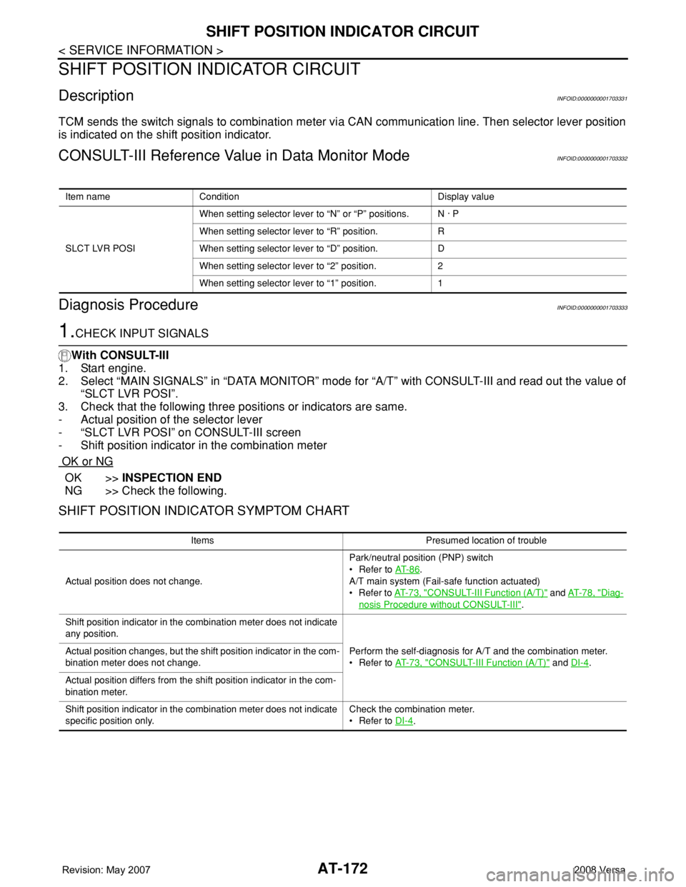
DescriptionINFOID:0000000001703331
TCM sends the switch signals to combination meter via CAN communication line. Then selector lever position
is indicated on the shift position indicator.
CONSULT-III Reference Value in Data Monitor ModeINFOID:0000000001703332
Diagnosis ProcedureINFOID:0000000001703333
1.CHECK INPUT SIGNALS
With CONSULT-III
1. Start engine.
2. Select “MAIN SIGNALS” in “DATA MONITOR” mode for “A/T” with CONSULT-III and read out the value of
“SLCT LVR POSI”.
3. Check that the following three positions or indicators are same.
- Actual position of the selector lever
- “SLCT LVR POSI” on CONSULT-III screen
- Shift position indicator in the combination meter
OK or NG
OK >>INSPECTION END
NG >> Check the following.
SHIFT POSITION INDICATOR SYMPTOM CHART
Item name Condition Display value
SLCT LVR POSIWhen setting selector lever to “N” or “P” positions. N · P
When setting selector lever to “R” position. R
When setting selector lever to “D” position. D
When setting selector lever to “2” position. 2
When setting selector lever to “1” position. 1
Items Presumed location of trouble
Actual position does not change.Park/neutral position (PNP) switch
• Refer to AT- 8 6
.
A/T main system (Fail-safe function actuated)
•Refer to AT- 7 3 , "
CONSULT-III Function (A/T)" and AT- 7 8 , "Diag-
nosis Procedure without CONSULT-III".
Shift position indicator in the combination meter does not indicate
any position.
Perform the self-diagnosis for A/T and the combination meter.
• Refer to AT- 7 3 , "
CONSULT-III Function (A/T)" and DI-4. Actual position changes, but the shift position indicator in the com-
bination meter does not change.
Actual position differs from the shift position indicator in the com-
bination meter.
Shift position indicator in the combination meter does not indicate
specific position only.Check the combination meter.
• Refer to DI-4
.
Page 987 of 2771

CVT-148
< SERVICE INFORMATION >
SHIFT POSITION INDICATOR CIRCUIT
SHIFT POSITION INDICATOR CIRCUIT
DescriptionINFOID:0000000001703659
TCM sends the switch signals to combination meter via CAN communication line. Then selector lever position
is indicated on the shift position indicator.
CONSULT-III Reference Value in Data Monitor ModeINFOID:0000000001703660
Diagnosis ProcedureINFOID:0000000001703661
1.CHECK INPUT SIGNALS
With CONSULT-III
1. Start engine.
2. Select “MAIN SIGNALS” in “DATA MONITOR” mode for “TRANSMISSION” with CONSULT-III and read
out the value of “RANGE”.
3. Check that the following three positions or indicators are same.
- Actual position of the selector lever
- “RANGE” on CONSULT-III screen
- Shift position indicator in the combination meter
OK or NG
OK >>INSPECTION END
NG >> Check the following.
SHIFT POSITION INDICATOR SYMPTOM CHART
Item name Condition Display value
RANGESelector lever in “N” or “P” position. N·P
Selector lever in “R” position. R
Selector lever in “D” position. D
Selector lever in “L” position. L
Items Presumed location of trouble
Actual position does not change.Park/neutral position switch
• Refer to CVT-65
.
CVT main system (Fail-safe function actuated)
• Refer to CVT-47, "
CONSULT-III Function (TRANSMISSION)".
Shift position indicator in the combination meter does not indicate
any position.
Perform the self-diagnosis for CVT and the combination meter.
• Refer to CVT-47, "
CONSULT-III Function (TRANSMISSION)"
and DI-4
. Actual position changes, but the shift position indicator in the com-
bination meter does not change.
Actual position differs from the shift position indicator in the com-
bination meter.
Shift position indicator in the combination meter does not indicate
specific position only.Check the combination meter.
• Refer to DI-4
.
Page 1465 of 2771
DTC P0500 VSS
EC-391
< SERVICE INFORMATION >
C
D
E
F
G
H
I
J
K
L
MA
EC
N
P O
DTC P0500 VSS
DescriptionINFOID:0000000001702900
NOTE:
•If DTC P0500 is displayed with DTC U1000 or U1001, first perform the trouble diagnosis for DTC
U1000, U1001. Refer to EC-143
.
•If DTC P0500 is displayed with DTC U1010, first perform the trouble diagnosis for DTC U1010. Refer
to EC-145
.
The vehicle speed signal is sent to the combination meter from “ABS actuator and electric unit (control unit)”
through CAN communication line. The combination meter then sends a signal to the ECM through CAN com-
munication line.
On Board Diagnosis LogicINFOID:0000000001702901
FAIL-SAFE MODE
When the malfunction is detected, ECM enters fail-safe mode.
DTC Confirmation ProcedureINFOID:0000000001702902
CAUTION:
Always drive vehicle at a safe speed.
NOTE:
If DTC Confirmation Procedure has been previously conducted, always turn ignition switch OFF and wait at
least 10 seconds before conducting the next test.
TESTING CONDITION:
Steps 1 and 2 may be conducted with the drive wheels lifted in the shop or by driving the vehicle. If a
road test is expected to be easier, it is unnecessary to lift the vehicle.
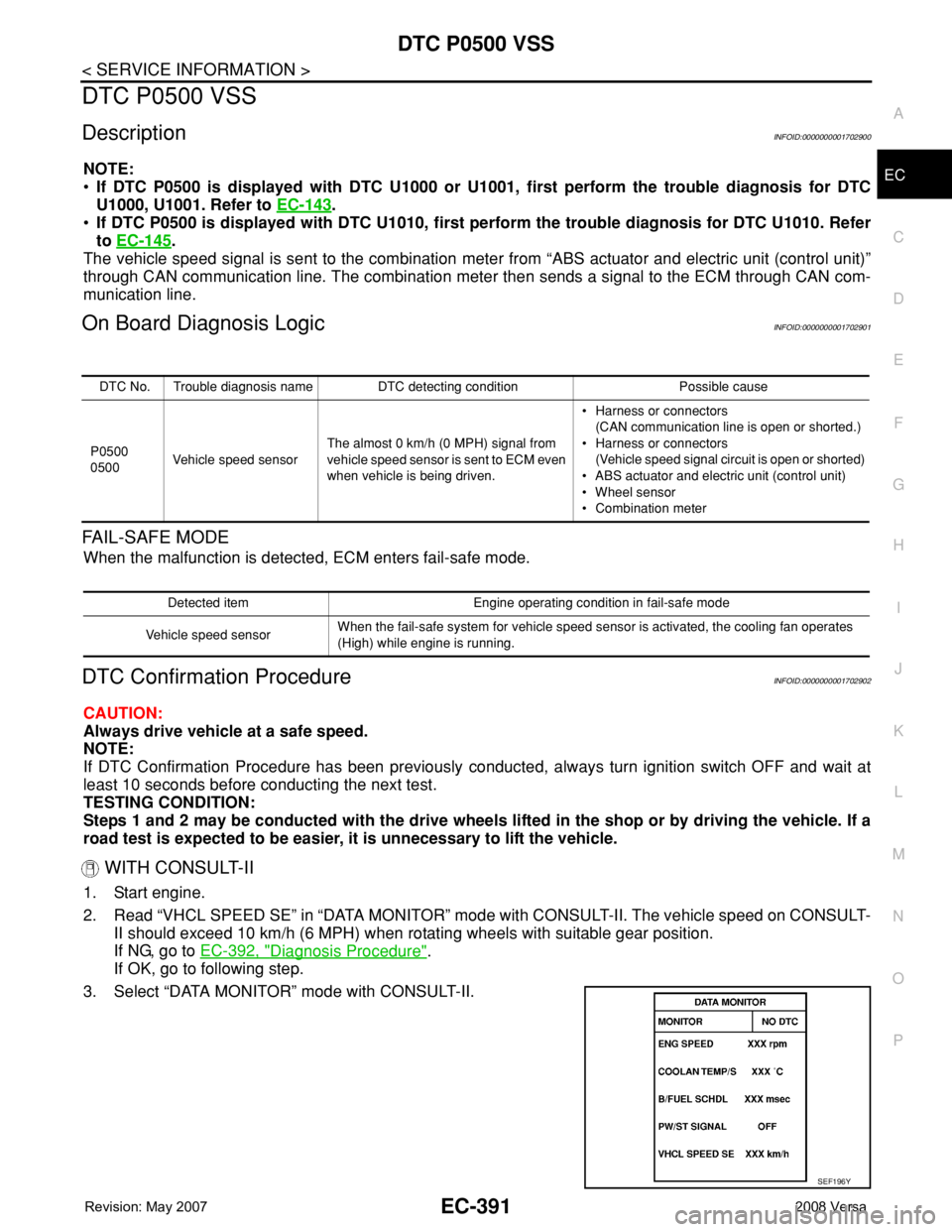
WITH CONSULT-II
1. Start engine.
2. Read “VHCL SPEED SE” in “DATA MONITOR” mode with CONSULT-II. The vehicle speed on CONSULT-
II should exceed 10 km/h (6 MPH) when rotating wheels with suitable gear position.
If NG, go to EC-392, "
Diagnosis Procedure".
If OK, go to following step.
3. Select “DATA MONITOR” mode with CONSULT-II.
DTC No. Trouble diagnosis name DTC detecting condition Possible cause
P0500
0500Vehicle speed sensorThe almost 0 km/h (0 MPH) signal from
vehicle speed sensor is sent to ECM even
when vehicle is being driven.• Harness or connectors
(CAN communication line is open or shorted.)
• Harness or connectors
(Vehicle speed signal circuit is open or shorted)
• ABS actuator and electric unit (control unit)
• Wheel sensor
• Combination meter
Detected item Engine operating condition in fail-safe mode
Vehicle speed sensorWhen the fail-safe system for vehicle speed sensor is activated, the cooling fan operates
(High) while engine is running.
SEF196Y
Page 2001 of 2771

LAN-10
< FUNCTION DIAGNOSIS >[CAN FUNDAMENTAL]
TROUBLE DIAGNOSIS
Example: Data link connector branch line open circuit
NOTE:
• When data link connector branch line is open, transmission and reception of CAN communication signals
are not affected. Therefore, no symptoms occur. However, be sure to repair malfunctioning circuit.
• The model (all units on CAN communication system are Diag on CAN) cannot perform CAN diagnosis with
CONSULT-III if the following error occurs. The error is judged by the symptom.
EPS control unit Normal operation.
Combination meter• Shift position indicator and OD OFF indicator turn OFF.
• Warning lamps turn ON.
ABS actuator and electric unit (control unit) Normal operation.
TCM No impact on operation.
IPDM E/R Normal operation.Unit name Symptom
SKIB8739E
Unit name Symptom
ECM
Normal operation. BCM
EPS control unit
Combination meter
ABS actuator and electric unit (control unit)
TCM
IPDM E/R
Error Difference of symptom
Data link connector branch line open circuit Normal operation.
CAN-H, CAN-L harness short-circuitMost of the units which are connected to the CAN communication
system enter fail-safe mode or are deactivated.
Page 2006 of 2771

DIAGNOSIS AND REPAIR WORKFLOW
LAN-15
< BASIC INSPECTION >[CAN FUNDAMENTAL]
C
D
E
F
G
H
I
J
L
MA
B
LAN
N
O
P
BASIC INSPECTION
DIAGNOSIS AND REPAIR WORKFLOW
Trouble Diagnosis Flow ChartINFOID:0000000001711211
Trouble Diagnosis ProcedureINFOID:0000000001711212
INTERVIEW WITH CUSTOMER
Interview with the customer is important to detect the root cause of CAN communication system errors and to
understand vehicle condition and symptoms for proper trouble diagnosis.
Points in interview• What: Parts name, system name
• When: Date, Frequency
• Where: Road condition, Place
• In what condition: Driving condition/environment
• Result: Symptom
NOTE:
• Check normal units as well as error symptoms.
- Example: Circuit between ECM and the combination meter is judged normal if the customer indicates
tachometer functions normally.
• When a CAN communication system error is present, multiple control units may malfunction or go into fail-
safe mode.
JSMIA0016GB
Page 2688 of 2771

EPS SYSTEM
STC-5
< SERVICE INFORMATION >[EPS]
C
D
E
F
H
I
J
K
L
MA
B
STC
N
O
P
SchematicINFOID:0000000001703873
COMPONENTS FUNCTION DESCRIPTION
CAN CommunicationINFOID:0000000001703874
SYSTEM DESCRIPTION
CAN (Controller Area Network) is a serial communication line for real time application. It is an on-vehicle mul-
tiplex communication line with high data communication speed and excellent error detection ability. Many elec-
tronic control units are equipped onto a vehicle, and each control unit shares information and links with other
control units during operation (not independent). In CAN communication, control units are connected with 2
communication lines (CAN-H line, CAN-L line) allowing a high rate of information transmission with less wiring.
Each control unit transmits/receives data but selectively reads required data only.
For details, refer to LAN-23, "
CAN System Specification Chart".
WGIA0187E
Component parts Function
EPS control unit
(Electric power steering control unit)• Outputs optimum assist torque signal to EPS motor.
• Reduces output signals to EPS motor and protects EPS motor and EPS control unit when us-
ing power steering continuously and excessively.
• As a fail-safe function, turned off output signal to EPS motor and then enters a manual steer-
ing state, if malfunction is detected in EPS system.
EPS motor Products assist torque by control signal from EPS control unit.
Torque sensor Detects steering wheel turning force and outputs sensor signal to EPS control unit.
Reduction gear Increases motor-produced assist torque by worm gear and transmits it to column shaft.
EPS warning lamp Illuminates if malfunction is detected in electrical system of EPS system.
ECMTransmits the following signals via CAN communication to EPS control unit.
• Engine status signal
ABS actuator and electric unit (con-
trol unit) (With ABS)Transmits the following signals via CAN communication to EPS control unit.
• Vehicle speed signal
Combination meterTransmits the following signals via CAN communication to EPS control unit.
• Vehicle speed signal
TCM (Without ABS)Transmits the following signals via CAN communication to EPS control unit.
• Vehicle speed signal