fuel tank NISSAN TIIDA 2008 Service Repair Manual
[x] Cancel search | Manufacturer: NISSAN, Model Year: 2008, Model line: TIIDA, Model: NISSAN TIIDA 2008Pages: 2771, PDF Size: 60.61 MB
Page 1026 of 2771
COMBINATION METERS
DI-5
< SERVICE INFORMATION >
C
D
E
F
G
H
I
J
L
MA
B
DI
N
O
P
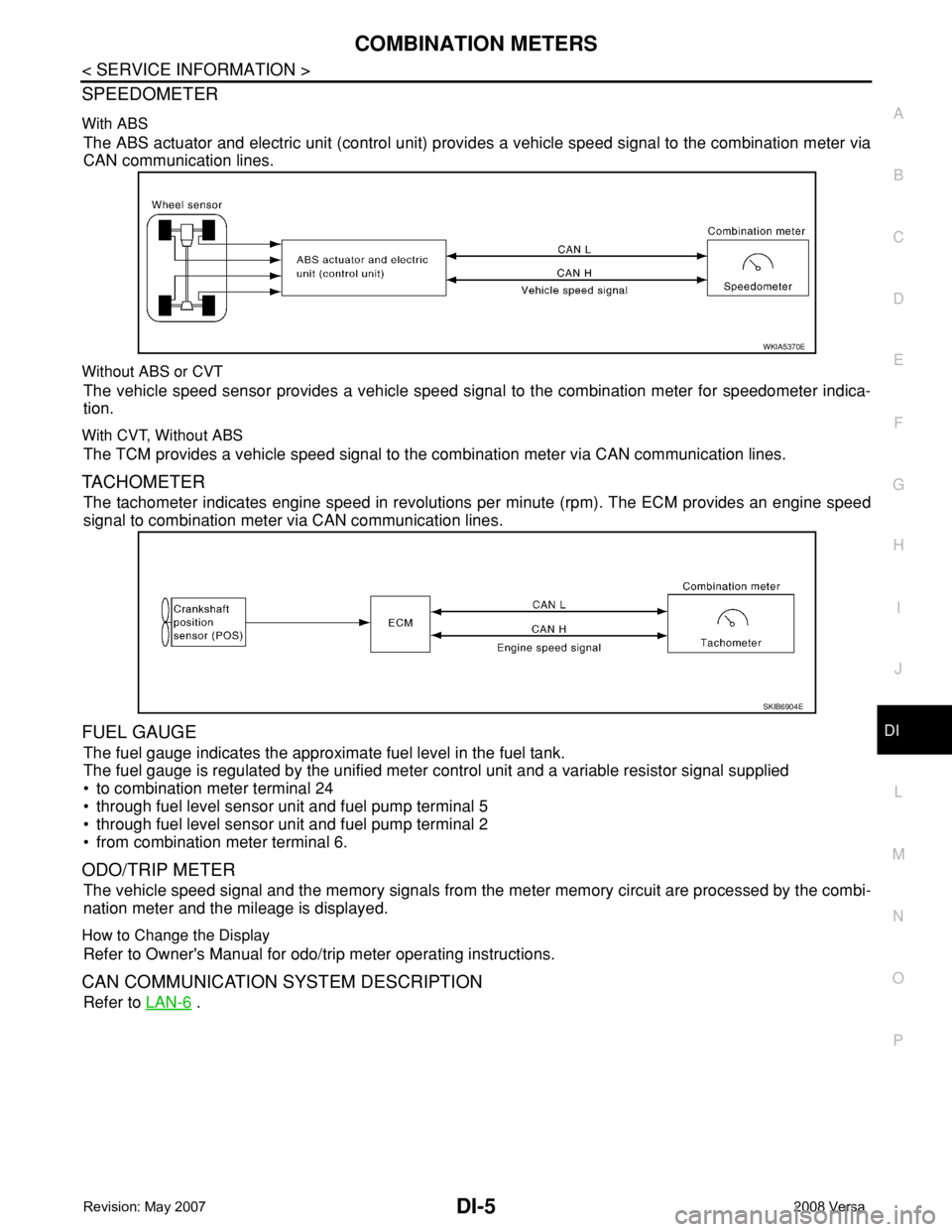
SPEEDOMETER
With ABS
The ABS actuator and electric unit (control unit) provides a vehicle speed signal to the combination meter via
CAN communication lines.
Without ABS or CVT
The vehicle speed sensor provides a vehicle speed signal to the combination meter for speedometer indica-
tion.
With CVT, Without ABS
The TCM provides a vehicle speed signal to the combination meter via CAN communication lines.
TACHOMETER
The tachometer indicates engine speed in revolutions per minute (rpm). The ECM provides an engine speed
signal to combination meter via CAN communication lines.
FUEL GAUGE
The fuel gauge indicates the approximate fuel level in the fuel tank.
The fuel gauge is regulated by the unified meter control unit and a variable resistor signal supplied
• to combination meter terminal 24
• through fuel level sensor unit and fuel pump terminal 5
• through fuel level sensor unit and fuel pump terminal 2
• from combination meter terminal 6.
ODO/TRIP METER
The vehicle speed signal and the memory signals from the meter memory circuit are processed by the combi-
nation meter and the mileage is displayed.
How to Change the Display
Refer to Owner's Manual for odo/trip meter operating instructions.
CAN COMMUNICATION SYSTEM DESCRIPTION
Refer to LAN-6 .
WKIA5370E
SKIB6904E
Page 1038 of 2771
COMBINATION METERS
DI-17
< SERVICE INFORMATION >
C
D
E
F
G
H
I
J
L
MA
B
DI
N
O
P
OK or NG
OK >> Check harness or connector between combination meter and vehicle speed sensor.
NG >> Replace vehicle speed sensor.
WITH CVT, WITHOUT ABS
1.CHECK COMBINATION METER INPUT SIGNAL
1. Start engine and select “METER/M&A” on CONSULT-III.
2. Using “SPEED METER” on “DATA MONITOR”, compare the value of “DATA MONITOR” with speedome-
ter pointer of combination meter.
OK or NG
OK >> Perform TCM self-diagnosis. Refer to CVT-47, "CONSULT-III Function (TRANSMISSION)" .
NG >> Replace combination meter. Refer to IP-11, "
Removal and Installation" .
Engine Speed Signal InspectionINFOID:0000000001704503
Symptom: Improper tachometer indication.
1.CHECK COMBINATION METER INPUT SIGNAL
1. Start engine and select “METER/M&A” on CONSULT-III.
2. Using “TACHO METER” on “DATA MONITOR”, compare the value of “DATA MONITOR” with tachometer
pointer of combination meter.
OK or NG
OK >> Perform ECM self-diagnosis. Refer to EC-109, "CONSULT-II Function (ENGINE)" .
NG >> Replace combination meter. Refer to IP-11, "
Removal and Installation" .
Fuel Level Sensor Signal InspectionINFOID:0000000001704504
Symptom:
• Improper fuel gauge indication.
• Low-fuel warning lamp indication is irregular.
NOTE:
The following symptoms do not indicate a malfunction.
• Depending on vehicle position or driving circumstance, the fuel level in the tank shifts and the indication may
fluctuate.
• If the vehicle is fueled with the ignition switch ON, the indication will update slowly.
• If the vehicle is tilted when the ignition switch is turned ON, fuel in the tank may flow to one direction result-
ing in a change of reading.
1.CHECK COMBINATION METER INPUT SIGNAL
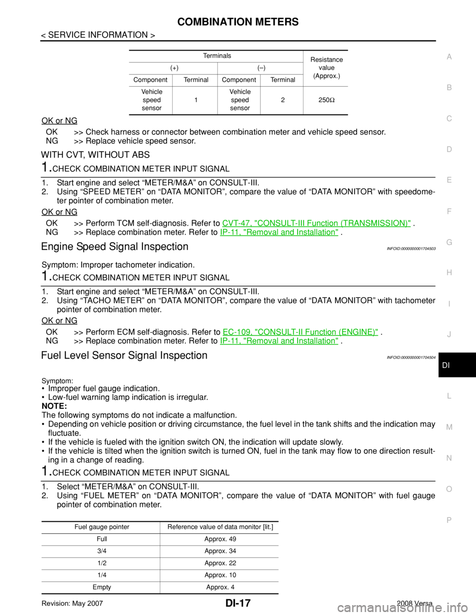
1. Select “METER/M&A” on CONSULT-III.
2. Using “FUEL METER” on “DATA MONITOR”, compare the value of “DATA MONITOR” with fuel gauge
pointer of combination meter.
Te r m i n a l s
Resistance
value
(Approx.) (+) (–)
Component Terminal Component Terminal
Ve h i c l e
speed
sensor1Vehicle
speed
sensor2250Ω
Fuel gauge pointer Reference value of data monitor [lit.]
Full Approx. 49
3/4 Approx. 34
1/2 Approx. 22
1/4 Approx. 10
Empty Approx. 4
Page 1040 of 2771
COMBINATION METERS
DI-19
< SERVICE INFORMATION >
C
D
E
F
G
H
I
J
L
MA
B
DI
N
O
P
OK >> Check fuel level sensor unit installation, and check whether the float arm interferes or binds with
any of the internal components in the fuel tank. Repair or replace malfunctioning part, if neces-
sary.
NG >> Replace fuel level sensor unit.
Fuel Gauge Fluctuates, Indicates Wrong Value, or VariesINFOID:0000000001704505
1.CHECK FUEL GAUGE FLUCTUATION
Test drive vehicle to see if gauge fluctuates only during driving or at the instant of stopping.
Does the indication value vary only during driving or at the at the instant of stopping?
YES >> The pointer fluctuation may be caused by fuel level change in the fuel tank. Condition is normal.
NO >> Ask the customer about the situation when the symptom occurs in detail, and perform the trouble
diagnosis.
Fuel Gauge Does Not Move to Full-positionINFOID:0000000001704506
1.OBSERVE FUEL GAUGE
Does it take a long time for the pointer to move to FULL position?
YES or NO
YES >> GO TO 2.
NO >> GO TO 3.
2.IDENTIFY FUELING CONDITION
Was the vehicle fueled with the ignition switch ON?
YES or NO
YES >> Be sure to fuel the vehicle with the ignition switch OFF. Otherwise, it will take a long time to move
to FULL position because of the characteristic of the fuel gauge.
NO >> GO TO 3.
3.OBSERVE VEHICLE POSITION
Is the vehicle parked on an incline?
YES or NO
YES >> Check the fuel level indication with vehicle on a level surface.
NO >> GO TO 4.
4.OBSERVE FUEL GAUGE POINTER
During driving, does the fuel gauge pointer move gradually toward EMPTY position?
YES or NO
YES >> Check the components. Refer to DI-19, "Electrical Component Inspection" .
NO >> The float arm may interfere or bind with any of the components in the fuel tank.
DTC [U1000] CAN Communication CircuitINFOID:0000000001704507
Symptom: Display CAN COMM CIRC [U1000] at the result of self-diagnosis for combination meter.
1.CHECK CAN COMMUNICATION
1. Select "SELF-DIAG RESULTS" mode for "METER/M&A" with CONSULT-III.
2. Print out CONSULT-III screen.
>> Go to "CAN SYSTEM". Refer to LAN-15, "
Trouble Diagnosis Flow Chart".
Electrical Component InspectionINFOID:0000000001704508
FUEL LEVEL SENSOR UNIT CHECK
For removal, refer to FL-5, "Removal and Installation" .
Check Fuel Level Sensor Unit and Fuel Pump
Page 1092 of 2771
EC-18
< SERVICE INFORMATION >
PRECAUTIONS
•Before replacing ECM, perform “ECM Terminals and Refer-
ence Value” inspection and make sure ECM functions prop-
erly. Refer to EC-102, "
ECM Terminal and Reference Value".
•Handle mass air flow sensor carefully to avoid damage.
•Do not disassemble mass air flow sensor.
•Do not clean mass air flow sensor with any type of detergent.
•Do not disassemble electric throttle control actuator.
•Even a slight leak in the air intake system can cause serious
incidents.
•Do not shock or jar the camshaft position sensor (PHASE),
crankshaft position sensor (POS).
•After performing each TROUBLE DIAGNOSIS, perform DTC
Confirmation Procedure or Overall Function Check.
The DTC should not be displayed in the DTC Confirmation
Procedure if the repair is completed. The Overall Function
Check should be a good result if the repair is completed.
•When measuring ECM signals with a circuit tester, never allow
the two tester probes to contact.
Accidental contact of probes will cause a short circuit and
damage the ECM power transistor.
•Do not use ECM ground terminals when measuring input/out-
put voltage. Doing so may result in damage to the ECM's tran-
sistor. Use a ground other than ECM terminals, such as the
ground.
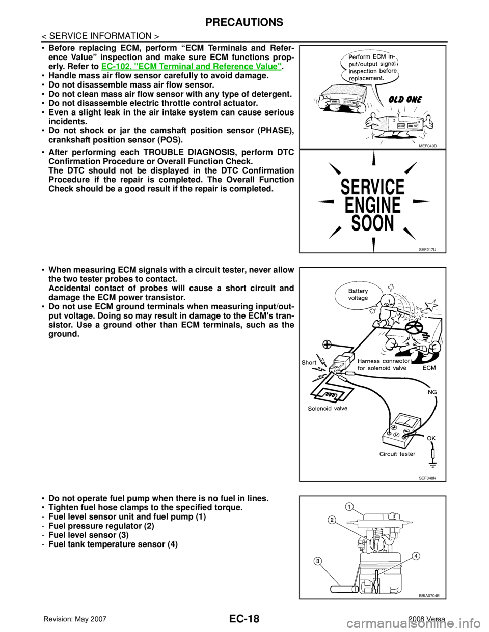
•Do not operate fuel pump when there is no fuel in lines.
•Tighten fuel hose clamps to the specified torque.
-Fuel level sensor unit and fuel pump (1)
-Fuel pressure regulator (2)
-Fuel level sensor (3)
-Fuel tank temperature sensor (4)
MEF040D
SEF217U
SEF348N
BBIA0704E
Page 1095 of 2771
PREPARATION
EC-21
< SERVICE INFORMATION >
C
D
E
F
G
H
I
J
K
L
MA
EC
N
P O
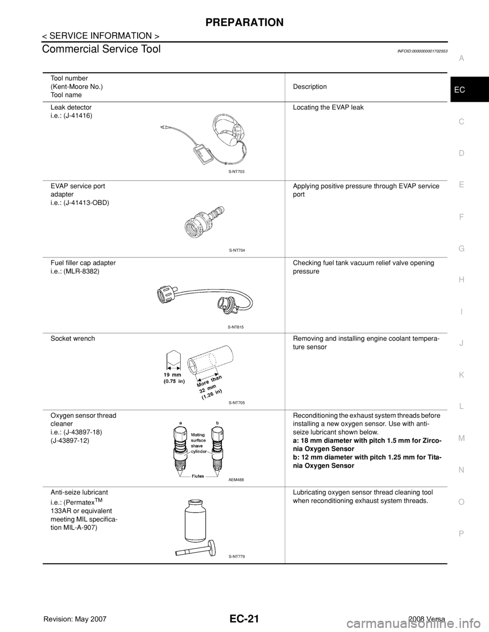
Commercial Service ToolINFOID:0000000001702553
Tool number
(Kent-Moore No.)
Tool nameDescription
Leak detector
i.e.: (J-41416)Locating the EVAP leak
EVAP service port
adapter
i.e.: (J-41413-OBD)Applying positive pressure through EVAP service
port
Fuel filler cap adapter
i.e.: (MLR-8382)Checking fuel tank vacuum relief valve opening
pressure
Socket wrench Removing and installing engine coolant tempera-
ture sensor
Oxygen sensor thread
cleaner
i.e.: (J-43897-18)
(J-43897-12)Reconditioning the exhaust system threads before
installing a new oxygen sensor. Use with anti-
seize lubricant shown below.
a: 18 mm diameter with pitch 1.5 mm for Zirco-
nia Oxygen Sensor
b: 12 mm diameter with pitch 1.25 mm for Tita-
nia Oxygen Sensor
Anti-seize lubricant
i.e.: (Permatex
TM
133AR or equivalent
meeting MIL specifica-
tion MIL-A-907)Lubricating oxygen sensor thread cleaning tool
when reconditioning exhaust system threads.
S-NT703
S-NT704
S-NT815
S-NT705
AEM488
S-NT779
Page 1105 of 2771
EVAPORATIVE EMISSION SYSTEM
EC-31
< SERVICE INFORMATION >
C
D
E
F
G
H
I
J
K
L
MA
EC
N
P O
EVAPORATIVE EMISSION SYSTEM
DescriptionINFOID:0000000001702563
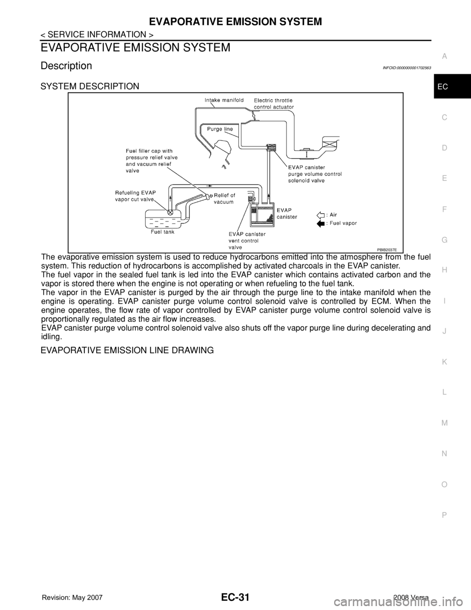
SYSTEM DESCRIPTION
The evaporative emission system is used to reduce hydrocarbons emitted into the atmosphere from the fuel
system. This reduction of hydrocarbons is accomplished by activated charcoals in the EVAP canister.
The fuel vapor in the sealed fuel tank is led into the EVAP canister which contains activated carbon and the
vapor is stored there when the engine is not operating or when refueling to the fuel tank.
The vapor in the EVAP canister is purged by the air through the purge line to the intake manifold when the
engine is operating. EVAP canister purge volume control solenoid valve is controlled by ECM. When the
engine operates, the flow rate of vapor controlled by EVAP canister purge volume control solenoid valve is
proportionally regulated as the air flow increases.
EVAP canister purge volume control solenoid valve also shuts off the vapor purge line during decelerating and
idling.
EVAPORATIVE EMISSION LINE DRAWING
PBIB2037E
Page 1108 of 2771
EC-34
< SERVICE INFORMATION >
EVAPORATIVE EMISSION SYSTEM
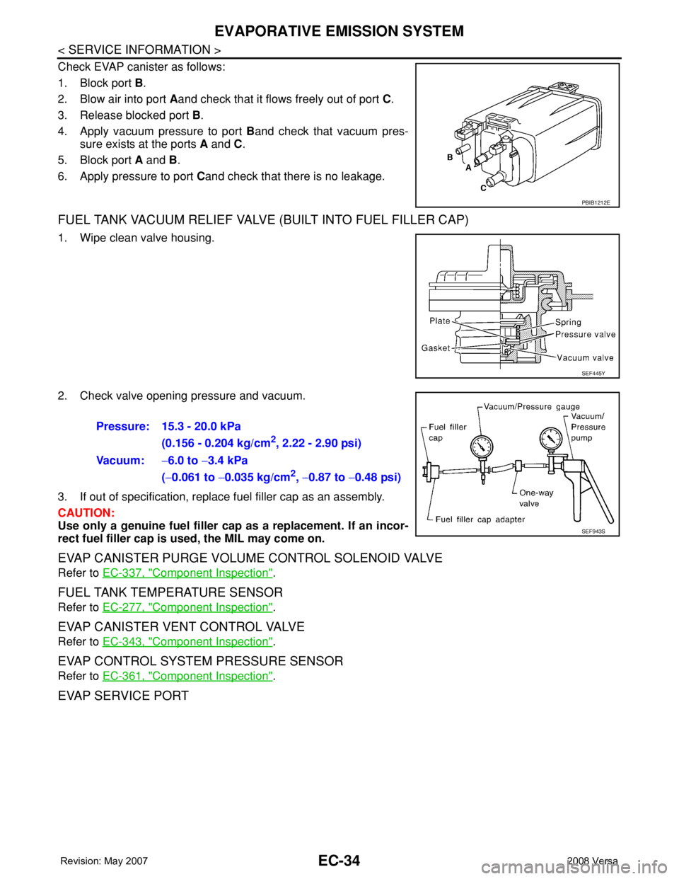
Check EVAP canister as follows:
1. Block port B.
2. Blow air into port Aand check that it flows freely out of port C.
3. Release blocked port B.
4. Apply vacuum pressure to port Band check that vacuum pres-
sure exists at the ports A and C.
5. Block port A and B.
6. Apply pressure to port Cand check that there is no leakage.
FUEL TANK VACUUM RELIEF VALVE (BUILT INTO FUEL FILLER CAP)
1. Wipe clean valve housing.
2. Check valve opening pressure and vacuum.
3. If out of specification, replace fuel filler cap as an assembly.
CAUTION:
Use only a genuine fuel filler cap as a replacement. If an incor-
rect fuel filler cap is used, the MIL may come on.
EVAP CANISTER PURGE VOLUME CONTROL SOLENOID VALVE
Refer to EC-337, "Component Inspection".
FUEL TANK TEMPERATURE SENSOR
Refer to EC-277, "Component Inspection".
EVAP CANISTER VENT CONTROL VALVE
Refer to EC-343, "Component Inspection".
EVAP CONTROL SYSTEM PRESSURE SENSOR
Refer to EC-361, "Component Inspection".
EVAP SERVICE PORT
PBIB1212E
SEF445Y
Pressure: 15.3 - 20.0 kPa
(0.156 - 0.204 kg/cm
2, 2.22 - 2.90 psi)
Vacuum:−6.0 to −3.4 kPa
(−0.061 to −0.035 kg/cm
2, −0.87 to −0.48 psi)
SEF943S
Page 1112 of 2771
EC-38
< SERVICE INFORMATION >
ON BOARD REFUELING VAPOR RECOVERY (ORVR)
ON BOARD REFUELING VAPOR RECOVERY (ORVR)
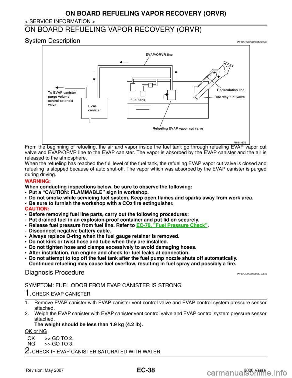
System DescriptionINFOID:0000000001702567
From the beginning of refueling, the air and vapor inside the fuel tank go through refueling EVAP vapor cut
valve and EVAP/ORVR line to the EVAP canister. The vapor is absorbed by the EVAP canister and the air is
released to the atmosphere.
When the refueling has reached the full level of the fuel tank, the refueling EVAP vapor cut valve is closed and
refueling is stopped because of auto shut-off. The vapor which was absorbed by the EVAP canister is purged
during driving.
WARNING:
When conducting inspections below, be sure to observe the following:
• Put a “CAUTION: FLAMMABLE” sign in workshop.
• Do not smoke while servicing fuel system. Keep open flames and sparks away from work area.
• Be sure to furnish the workshop with a CO
2 fire extinguisher.
CAUTION:
• Before removing fuel line parts, carry out the following procedures:
- Put drained fuel in an explosion-proof container and put lid on securely.
- Release fuel pressure from fuel line. Refer to EC-78, "
Fuel Pressure Check".
- Disconnect negative battery cable.
• Always replace O-ring when the fuel gauge retainer is removed.
• Do not kink or twist hose and tube when they are installed.
• Do not tighten hose and clamps excessively to avoid damaging hoses.
• After installation, run engine and check for fuel leaks at connection.
• Do not attempt to top off the fuel tank after the fuel pump nozzle shuts off automatically.
Continued refueling may cause fuel overflow, resulting in fuel spray and possibly a fire.
Diagnosis ProcedureINFOID:0000000001702568
SYMPTOM: FUEL ODOR FROM EVAP CANISTER IS STRONG.
1.CHECK EVAP CANISTER
1. Remove EVAP canister with EVAP canister vent control valve and EVAP control system pressure sensor
attached.
2. Weigh the EVAP canister with EVAP canister vent control valve and EVAP control system pressure sensor
attached.
The weight should be less than 1.9 kg (4.2 lb).
OK or NG
OK >> GO TO 2.
NG >> GO TO 3.
2.CHECK IF EVAP CANISTER SATURATED WITH WATER
PBIB1387E
Page 1113 of 2771
ON BOARD REFUELING VAPOR RECOVERY (ORVR)
EC-39
< SERVICE INFORMATION >
C
D
E
F
G
H
I
J
K
L
MA
EC
N
P O
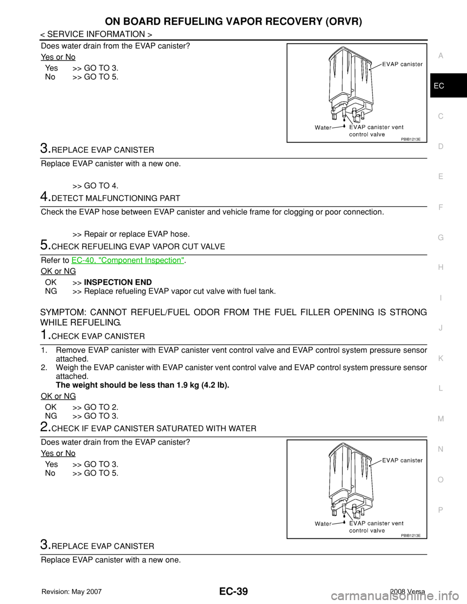
Does water drain from the EVAP canister?
Ye s o r N o
Yes >> GO TO 3.
No >> GO TO 5.
3.REPLACE EVAP CANISTER
Replace EVAP canister with a new one.
>> GO TO 4.
4.DETECT MALFUNCTIONING PART
Check the EVAP hose between EVAP canister and vehicle frame for clogging or poor connection.
>> Repair or replace EVAP hose.
5.CHECK REFUELING EVAP VAPOR CUT VALVE
Refer to EC-40, "
Component Inspection".
OK or NG
OK >>INSPECTION END
NG >> Replace refueling EVAP vapor cut valve with fuel tank.
SYMPTOM: CANNOT REFUEL/FUEL ODOR FROM THE FUEL FILLER OPENING IS STRONG
WHILE REFUELING.
1.CHECK EVAP CANISTER
1. Remove EVAP canister with EVAP canister vent control valve and EVAP control system pressure sensor
attached.
2. Weigh the EVAP canister with EVAP canister vent control valve and EVAP control system pressure sensor
attached.
The weight should be less than 1.9 kg (4.2 lb).
OK or NG
OK >> GO TO 2.
NG >> GO TO 3.
2.CHECK IF EVAP CANISTER SATURATED WITH WATER
Does water drain from the EVAP canister?
Ye s o r N o
Yes >> GO TO 3.
No >> GO TO 5.
3.REPLACE EVAP CANISTER
Replace EVAP canister with a new one.
PBIB1213E
PBIB1213E
Page 1114 of 2771
EC-40
< SERVICE INFORMATION >
ON BOARD REFUELING VAPOR RECOVERY (ORVR)
>> GO TO 4.
4.DETECT MALFUNCTIONING PART
Check the EVAP hose between EVAP canister and vehicle frame for clogging or poor connection.
>> Repair or replace EVAP hose.
5.CHECK VENT HOSES AND VENT TUBES
Check hoses and tubes between EVAP canister and refueling EVAP vapor cut valve for clogging, kink, loose-
ness and improper connection.
OK or NG
OK >> GO TO 6.
NG >> Repair or replace hoses and tubes.
6.CHECK FILLER NECK TUBE
Check recirculation line for clogging, dents and cracks.
OK or NG
OK >> GO TO 7.
NG >> Replace filler neck tube.
7.CHECK REFUELING EVAP VAPOR CUT VALVE
Refer to EC-40, "
Component Inspection".
OK or NG
OK >> GO TO 8.
NG >> Replace refueling EVAP vapor cut valve with fuel tank.
8.CHECK FUEL FILLER TUBE
Check filler neck tube and hose connected to the fuel tank for clogging, dents and cracks.
OK or NG
OK >> GO TO 9.
NG >> Replace fuel filler tube.
9.CHECK ONE-WAY FUEL VALVE-I
Check one-way valve for clogging.
OK or NG
OK >> GO TO 10.
NG >> Repair or replace one-way fuel valve with fuel tank.
10.CHECK ONE-WAY FUEL VALVE-II
1. Make sure that fuel is drained from the tank.
2. Remove fuel filler tube and hose.
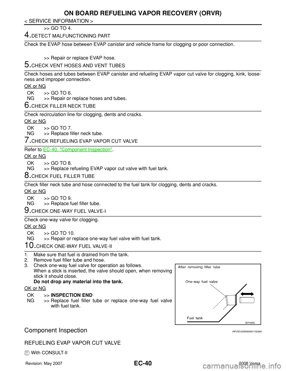
3. Check one-way fuel valve for operation as follows.
When a stick is inserted, the valve should open, when removing
stick it should close.
Do not drop any material into the tank.
OK or NG
OK >>INSPECTION END
NG >> Replace fuel filler tube or replace one-way fuel valve
with fuel tank.
Component InspectionINFOID:0000000001702569
REFUELING EVAP VAPOR CUT VALVE
With CONSULT-II
SEF665U