page 71 NISSAN TIIDA 2008 Service Repair Manual
[x] Cancel search | Manufacturer: NISSAN, Model Year: 2008, Model line: TIIDA, Model: NISSAN TIIDA 2008Pages: 2771, PDF Size: 60.61 MB
Page 3 of 2771

PLEASEHELPMAKETHISSERVICEMANUALBETTER!
YourcommentsareimportanttoNISSANandwillhelpustoimproveourServiceManuals.
UsethisformtoreportanyissuesorcommentsyoumayhaveregardingourServiceManuals.
Pleaseprintthisformandtypeorwriteyourcommentsbelow.Mailorfaxto:
NissanNorthAmerica,Inc.
TechnicalServiceInformation
39001SunriseDrive,P.O.Box9200
FarmingtonHills,MIUSA48331
FAX:(248)488-3910
SERVICEMANUAL:Model:Year:
PUBLICATIONNO.(Refer to Quick Reference Index ):
Pleasedescribeany Service Manualissuesorproblemsindetail:
Pagenumber(s)Note:Pleaseincludeacopyofeachpage,markedwithyourcomments.
Arethetroublediagnosisprocedureslogicalandeasytouse?(circleyouranswer)YESNO
Ifno,whatpagenumber(s)?Note:Pleaseincludeacopyofeachpage,markedwithyourcomments.
Pleasedescribetheissueorproblemindetail:
Istheorganizationofthemanualclearandeasytofollow?(circleyouranswer)YESNO
Pleasecomment:
WhatinformationshouldbeincludedinNISSANServiceManualstobettersupportyouinservicingor
repairingcustomervehicles?
DATE:YOURNAME:POSITION:
DEALER:DEALERNO.:ADDRESS:
CITY:STATE/PROV./COUNTRY:ZIP/POSTALCODE:
Page 17 of 2771

INDEX FOR DTC
AT-5
< SERVICE INFORMATION >
D
E
F
G
H
I
J
K
L
MA
B
AT
N
O
P
SERVICE INFORMATION
INDEX FOR DTC
Alphabetical IndexINFOID:0000000001703149
NOTE:
If DTC “CAN COMM CIRCUIT” is displayed with other DTCs, first perform the trouble diagnosis for
DTC “CAN COMM CIRCUIT”. Refer to AT- 8 3
.
*1: These numbers is prescribed by SAE J2012.
*2: When the fail-safe operation occurs, the MIL illuminates.
*3: The MIL illuminates when both the “Revolution sensor signal” and the “Vehicle speed sensor signal” meet the fail-safe condition at
the same time.
DTC No. IndexINFOID:0000000001703150
NOTE:
If DTC “CAN COMM CIRCUIT” is displayed with other DTCs, first perform the trouble diagnosis for
DTC “CAN COMM CIRCUIT”. Refer to AT- 8 3
.
Items
(CONSULT-III screen terms)DTC
Reference page
CONSULT-III or GST
*1
A/T 1ST GR FNCTN P0731AT-105
A/T 2ND GR FNCTN P0732AT-108
A/T 3RD GR FNCTN P0733AT- 111
A/T 4TH GR FNCTN P0734AT- 11 4
A/T TCC S/V FNCTN P0744AT-124
ATF TEMP SEN/CIRC P0710AT- 9 1
BATT/FLUID TEMP SEN —AT-152
CAN COMM CIRCUIT U1000AT- 8 3
CONTROL UNIT (RAM) —AT-163
CONTROL UNIT (ROM) —AT-163
ENGINE SPEED SIG P0725AT-101
LINE PRESSURE S/V P0745AT-129
OVERRUN CLUTCH S/V P1760AT-144
PNP SW/CIRC P0705AT- 8 6
SHIFT SOLENOID/V A*2P0750AT-134
SHIFT SOLENOID/V B*2P0755AT-139
T/C CLUTCH SOL/V P0740AT- 11 9
TURBINE SENSOR —AT-158
VHCL SPEED SEN-A/T*3P0720AT- 9 6
VHCL SPEED SEN-MTR —AT-149
DTC
Items
(CONSULT-III screen terms) Reference page
CONSULT-III or GST
*1
P0705 PNP SW/CIRCAT- 8 6
P0710 ATF TEMP SEN/CIRCAT- 9 1
P0720
VHCL SPEED SEN-A/T*3AT- 9 6
P0725 ENGINE SPEED SIGAT- 1 0 1
P0731 A/T 1ST GR FNCTNAT- 1 0 5
Page 18 of 2771

AT-6
< SERVICE INFORMATION >
INDEX FOR DTC
*1: These numbers is prescribed by SAE J2012.
*2: When the fail-safe operation occurs, the MIL illuminates.
*3: The MIL illuminates when both the “Revolution sensor signal” and the “Vehicle speed sensor signal” meet the fail-safe condition at
the same time.P0732 A/T 2ND GR FNCTNAT- 1 0 8
P0733 A/T 3RD GR FNCTNAT- 111
P0734 A/T 4TH GR FNCTNAT- 11 4
P0740 T/C CLUTCH SOL/VAT- 11 9
P0744 A/T TCC S/V FNCTNAT- 1 2 4
P0745 LINE PRESSURE S/VAT- 1 2 9
P0750
SHIFT SOLENOID/V A*2AT- 1 3 4
P0755
SHIFT SOLENOID/V B*2AT- 1 3 9
P1760 OVERRUN CLUTCH S/VAT- 1 4 4
U1000 CAN COMM CIRCUITAT- 8 3
— BATT/FLUID TEMP SENAT- 1 5 2
— CONTROL UNIT (RAM)AT- 1 6 3
— CONTROL UNIT (ROM)AT- 1 6 3
— TURBINE SENSORAT- 1 5 8
— VHCL SPEED SEN-MTRAT- 1 4 9
DTC
Items
(CONSULT-III screen terms) Reference page
CONSULT-III or GST
*1
Page 20 of 2771
AT-8
< SERVICE INFORMATION >
PRECAUTIONS
• Be sure to turn the ignition switch OFF and disconnect battery negative cable from battery negative
terminal before any repair or inspection work. The open/short circuit of related switches, sensors,
solenoid valves, etc. will cause the MIL to light up.
• Be sure to connect and lock the connectors securely after work. A loose (unlocked) connector will
cause the MIL to light up due to an open circuit. (Be sure the connectors are free from water, grease,
dirt, bent terminals, etc.)
• Be sure to route and secure the harnesses properly after work. Interference of the harness with a
bracket, etc. may cause the MIL to light up due to a short circuit.
• Be sure to erase the unnecessary malfunction information (repairs completed) from the TCM and
ECM before returning the vehicle to the customer.
PrecautionINFOID:0000000001703154
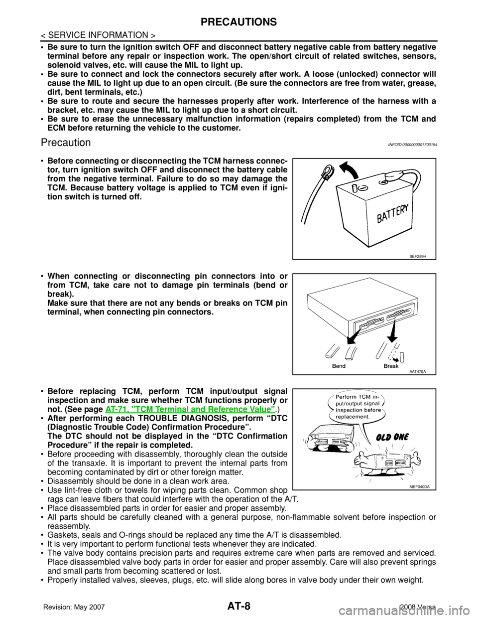
•Before connecting or disconnecting the TCM harness connec-
tor, turn ignition switch OFF and disconnect the battery cable
from the negative terminal. Failure to do so may damage the
TCM. Because battery voltage is applied to TCM even if igni-
tion switch is turned off.
•When connecting or disconnecting pin connectors into or
from TCM, take care not to damage pin terminals (bend or
break).
Make sure that there are not any bends or breaks on TCM pin
terminal, when connecting pin connectors.
•Before replacing TCM, perform TCM input/output signal
inspection and make sure whether TCM functions properly or
not. (See page AT-71, "
TCM Terminal and Reference Value".)
•After performing each TROUBLE DIAGNOSIS, perform “DTC
(Diagnostic Trouble Code) Confirmation Procedure”.
The DTC should not be displayed in the “DTC Confirmation
Procedure” if the repair is completed.
• Before proceeding with disassembly, thoroughly clean the outside
of the transaxle. It is important to prevent the internal parts from
becoming contaminated by dirt or other foreign matter.
• Disassembly should be done in a clean work area.
• Use lint-free cloth or towels for wiping parts clean. Common shop
rags can leave fibers that could interfere with the operation of the A/T.
• Place disassembled parts in order for easier and proper assembly.
• All parts should be carefully cleaned with a general purpose, non-flammable solvent before inspection or
reassembly.
• Gaskets, seals and O-rings should be replaced any time the A/T is disassembled.
• It is very important to perform functional tests whenever they are indicated.
• The valve body contains precision parts and requires extreme care when parts are removed and serviced.
Place disassembled valve body parts in order for easier and proper assembly. Care will also prevent springs
and small parts from becoming scattered or lost.
• Properly installed valves, sleeves, plugs, etc. will slide along bores in valve body under their own weight.
SEF289H
AAT470A
MEF040DA
Page 61 of 2771
TROUBLE DIAGNOSIS
AT-49
< SERVICE INFORMATION >
D
E
F
G
H
I
J
K
L
MA
B
AT
N
O
P
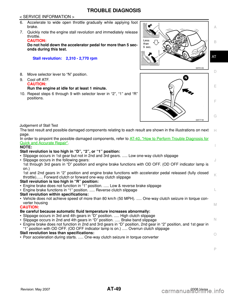
6. Accelerate to wide open throttle gradually while applying foot
brake.
7. Quickly note the engine stall revolution and immediately release
throttle.
CAUTION:
Do not hold down the accelerator pedal for more than 5 sec-
onds during this test.
8. Move selector lever to “N” position.
9. Cool off ATF.
CAUTION:
Run the engine at idle for at least 1 minute.
10. Repeat steps 6 through 9 with selector lever in “2”, “1” and “R”
positions.
Judgement of Stall Test
The test result and possible damaged components relating to each result are shown in the illustrations on next
page.
In order to pinpoint the possible damaged components, refer to AT-40, "
How to Perform Trouble Diagnosis for
Quick and Accurate Repair".
NOTE:
Stall revolution is too high in “D”, “2”, or “1” position:
• Slippage occurs in 1st gear but not in 2nd and 3rd gears. ..... Low one-way clutch slippage
• Slippage occurs in the following gears:
1st through 3rd gears in “D” position and engine brake functions with OD OFF. (OD OFF indicator lamp is
on.)
1st and 2nd gears in “2” position and engine brake functions with accelerator pedal released (fully closed
throttle)...... Forward clutch or forward one-way clutch slippage
Stall revolution is too high in “R” position:
• Engine brake does not function in “1” position. ..... Low & reverse brake slippage
• Engine brake functions in “1” position. ..... Reverse clutch slippage
Stall revolution within specifications:
• Vehicle does not achieve speed of more than 80 km/h (50 MPH). ..... One-way clutch seizure in torque con-
verter housing
CAUTION:
Be careful because automatic fluid temperature increases abnormally:
• Slippage occurs in 3rd and 4th gears in “D” position. ..... High clutch slippage
• Slippage occurs in 2nd and 4th gears in “D” position. ..... Brake band slippage
• Engine brake does not function in 2nd and 3rd gears in “D” position, 2nd gear in “2” position, and 1st gear in
“1” position with OD OFF. (OD OFF indicator lamp is on.) ..... Overrun clutch slippage
Stall revolution less than specifications:
• Poor acceleration during starts. ..... One-way clutch seizure in torque converter Stall revolution: 2,310 - 2,770 rpm
SAT514G
SAT771B
Page 74 of 2771
AT-62
< SERVICE INFORMATION >
TROUBLE DIAGNOSIS
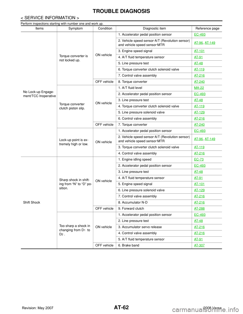
Perform inspections starting with number one and work up.
Items Symptom Condition Diagnostic item Reference page
No Lock-up Engage-
ment/TCC InoperativeTorque converter is
not locked up.ON vehicle1. Accelerator pedal position sensorEC-493
2. Vehicle speed sensor·A/T (Revolution sensor)
and vehicle speed sensor·MTRAT- 9 6, AT- 1 4 9
3. Engine speed signalAT- 1 0 1
4. A/T fluid temperature sensorAT- 9 1
5. Line pressure testAT- 4 8
6. Torque converter clutch solenoid valveAT- 11 9
7. Control valve assemblyAT- 2 1 6
OFF vehicle 8. Torque converterAT- 2 4 0
Torque converter
clutch piston slip.ON vehicle1. A/T fluid levelMA-22
2. Accelerator pedal position sensorEC-493
3. Line pressure testAT- 4 8
4. Torque converter clutch solenoid valveAT- 11 9
5. Line pressure solenoid valveAT- 1 2 9
6. Control valve assemblyAT- 2 1 6
OFF vehicle 7. Torque converterAT- 2 4 0
Lock-up point is ex-
tremely high or low.ON vehicle1. Accelerator pedal position sensorEC-4932. Vehicle speed sensor·A/T (Revolution sensor)
and vehicle speed sensor·MTRAT- 9 6, AT- 1 4 9
3. Torque converter clutch solenoid valveAT- 11 9
4. Control valve assemblyAT- 2 1 6
Shift ShockSharp shock in shift-
ing from “N” to “D” po-
sition.ON vehicle1. Engine idling speedEC-73
2. Accelerator pedal position sensorEC-493
3. Line pressure testAT- 4 8
4. A/T fluid temperature sensorAT- 9 1
5. Engine speed signalAT- 1 0 1
6. Line pressure solenoid valveAT- 1 2 9
7. Control valve assemblyAT- 2 1 6
8. Accumulator N-DAT- 2 1 6
OFF vehicle 9. Forward clutchAT- 2 8 8
Too sharp a shock in
changing from D
1 to
D
2 .ON vehicle1. Accelerator pedal position sensorEC-493
2. Line pressure testAT- 4 8
3. Accumulator servo releaseAT- 2 1 6
4. Control valve assemblyAT- 2 1 6
5. A/T fluid temperature sensorAT- 9 1
OFF vehicle 6. Brake bandAT- 3 0 7
Page 75 of 2771
TROUBLE DIAGNOSIS
AT-63
< SERVICE INFORMATION >
D
E
F
G
H
I
J
K
L
MA
B
AT
N
O
P
Shift ShockToo sharp a shock in
changing from D
2 to
D
3 .ON vehicle1. Accelerator pedal position sensorEC-493
2. Line pressure testAT- 4 8
3. Control valve assemblyAT- 2 1 6
OFF vehicle4. High clutchAT- 2 8 45. Brake bandAT- 3 0 7
Too sharp a shock in
changing from D
3 to
D
4 .ON vehicle1. Accelerator pedal position sensorEC-493
2. Line pressure testAT- 4 8
3. Control valve assemblyAT- 2 1 6
OFF vehicle4. Brake bandAT- 3 0 75. Overrun clutchAT- 2 8 8
6. Forward one-way clutchAT- 2 9 9
Gear change shock
during deceleration by
releasing accelerator
pedal.ON vehicle1. Accelerator pedal position sensorEC-4932. Line pressure testAT- 4 8
3. Overrun clutch solenoid valveAT- 1 4 4
4. Control valve assemblyAT- 2 1 6
Large shock in chang-
ing from 1
2 to 11 in
“1” position.ON vehicle 1. Control valve assemblyAT- 2 1 6OFF vehicle 2. Low & reverse brakeAT- 2 9 5
Improper Shift TimingToo high a gear
change point from D
1
to D
2 , from D2 to D3 ,
from D
3 to D4 .ON vehicle1. Accelerator pedal position sensorEC-493
2. Vehicle speed sensor·A/T (Revolution sensor)
and vehicle speed sensor·MTRAT- 9 6, AT- 1 4 9
3. Shift solenoid valve AAT- 1 3 4
4. Shift solenoid valve BAT- 1 3 9
Gear change directly
from D
1 to D3 occurs.ON vehicle1. A/T fluid levelMA-222. Accumulator servo releaseAT- 2 1 6
OFF vehicle 3. Brake bandAT- 3 0 7
Too high a change
point from D
4 to D3 ,
from D
3 to D 2 , from
D
2 to D1 .ON vehicle1. Accelerator pedal position sensorEC-493
2. Vehicle speed sensor·A/T (Revolution sensor)
and vehicle speed sensor·MTRAT- 9 6, AT- 1 4 9
Kickdown does not
operate when de-
pressing accelerator
pedal in D
4 within
kickdown vehicle
speed.ON vehicle1. Accelerator pedal position sensorEC-493
2. Vehicle speed sensor·A/T (Revolution sensor)
and vehicle speed sensor·MTRAT- 9 6, AT- 1 4 9
3. Shift solenoid valve AAT- 1 3 4
4. Shift solenoid valve BAT- 1 3 9
Kickdown operates or
engine overruns when
depressing accelera-
tor pedal in D
4 be-
yond kickdown
vehicle speed limit.ON vehicle1. Vehicle speed sensor·A/T (Revolution sensor)
and vehicle speed sensor·MTRAT- 9 6
, AT- 1 4 9
2. Accelerator pedal position sensorEC-493
3. Shift solenoid valve AAT- 1 3 4
4. Shift solenoid valve BAT- 1 3 9
Gear change from 22
to 2
3 in “2” position.ON vehicle1. PNP switch adjustmentAT- 2 1 92. Control cable adjustmentAT- 2 0 7
Gear change from 11
to 1
2 in “1” position.ON vehicle1. PNP switch adjustmentAT- 2 1 92. Control cable adjustmentAT- 2 0 7
Items Symptom Condition Diagnostic item Reference page
Page 76 of 2771
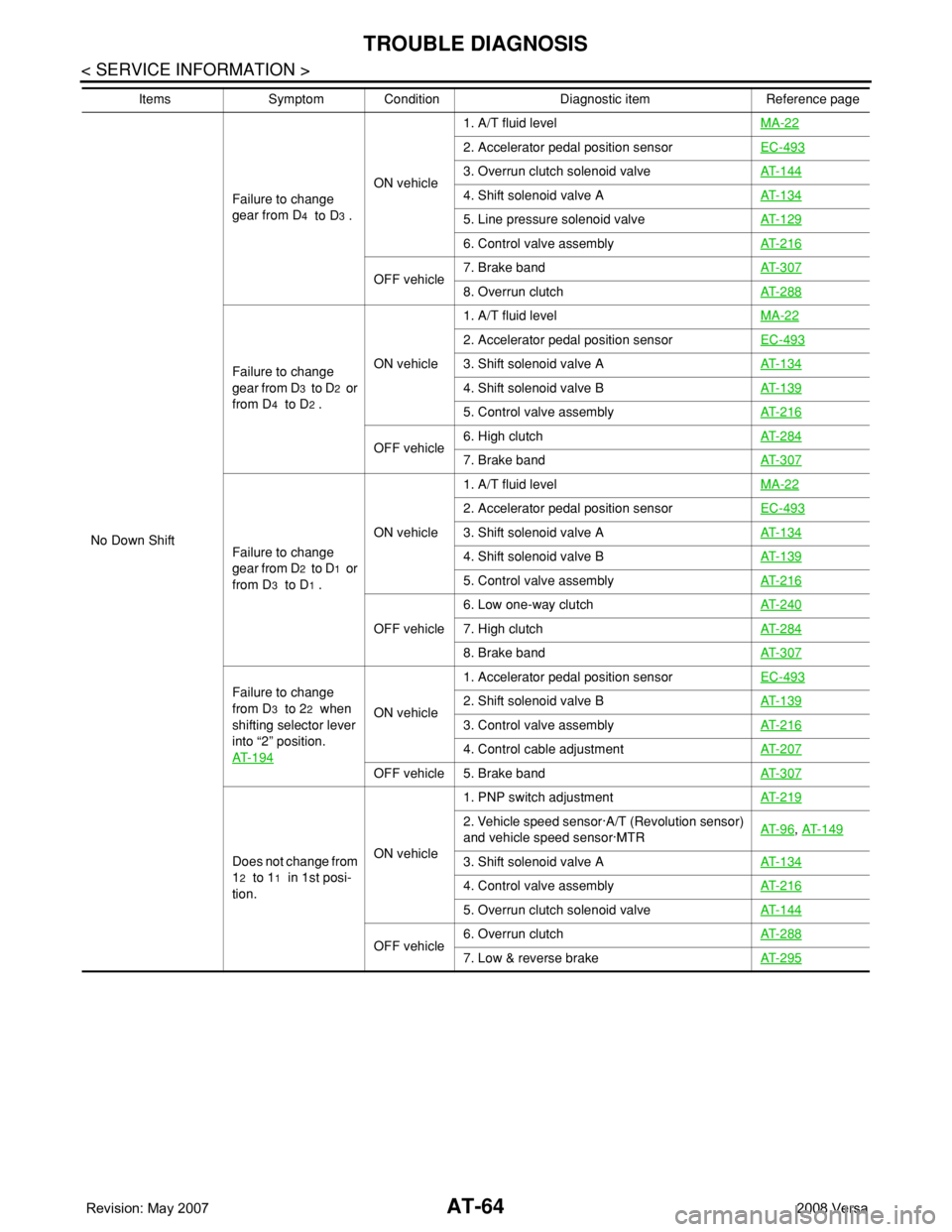
AT-64
< SERVICE INFORMATION >
TROUBLE DIAGNOSIS
No Down ShiftFailure to change
gear from D
4 to D3 .ON vehicle1. A/T fluid levelMA-22
2. Accelerator pedal position sensorEC-493
3. Overrun clutch solenoid valveAT- 1 4 4
4. Shift solenoid valve A AT- 1 3 4
5. Line pressure solenoid valveAT- 1 2 9
6. Control valve assemblyAT- 2 1 6
OFF vehicle7. Brake bandAT- 3 0 78. Overrun clutchAT- 2 8 8
Failure to change
gear from D
3 to D2 or
from D
4 to D2 .ON vehicle1. A/T fluid levelMA-22
2. Accelerator pedal position sensorEC-493
3. Shift solenoid valve AAT- 1 3 4
4. Shift solenoid valve BAT- 1 3 9
5. Control valve assemblyAT- 2 1 6
OFF vehicle6. High clutchAT- 2 8 47. Brake bandAT- 3 0 7
Failure to change
gear from D
2 to D1 or
from D
3 to D1 .ON vehicle1. A/T fluid levelMA-22
2. Accelerator pedal position sensorEC-493
3. Shift solenoid valve AAT- 1 3 4
4. Shift solenoid valve BAT- 1 3 9
5. Control valve assemblyAT- 2 1 6
OFF vehicle6. Low one-way clutchAT- 2 4 07. High clutchAT- 2 8 4
8. Brake bandAT- 3 0 7
Failure to change
from D
3 to 22 when
shifting selector lever
into “2” position.
AT- 1 9 4ON vehicle1. Accelerator pedal position sensorEC-4932. Shift solenoid valve BAT- 1 3 9
3. Control valve assembly AT- 2 1 6
4. Control cable adjustmentAT- 2 0 7
OFF vehicle 5. Brake bandAT- 3 0 7
Does not change from
1
2 to 11 in 1st posi-
tion.ON vehicle1. PNP switch adjustmentAT- 2 1 9
2. Vehicle speed sensor·A/T (Revolution sensor)
and vehicle speed sensor·MTRAT- 9 6, AT- 1 4 9
3. Shift solenoid valve AAT- 1 3 4
4. Control valve assemblyAT- 2 1 6
5. Overrun clutch solenoid valveAT- 1 4 4
OFF vehicle6. Overrun clutchAT- 2 8 87. Low & reverse brakeAT- 2 9 5
Items Symptom Condition Diagnostic item Reference page
Page 77 of 2771
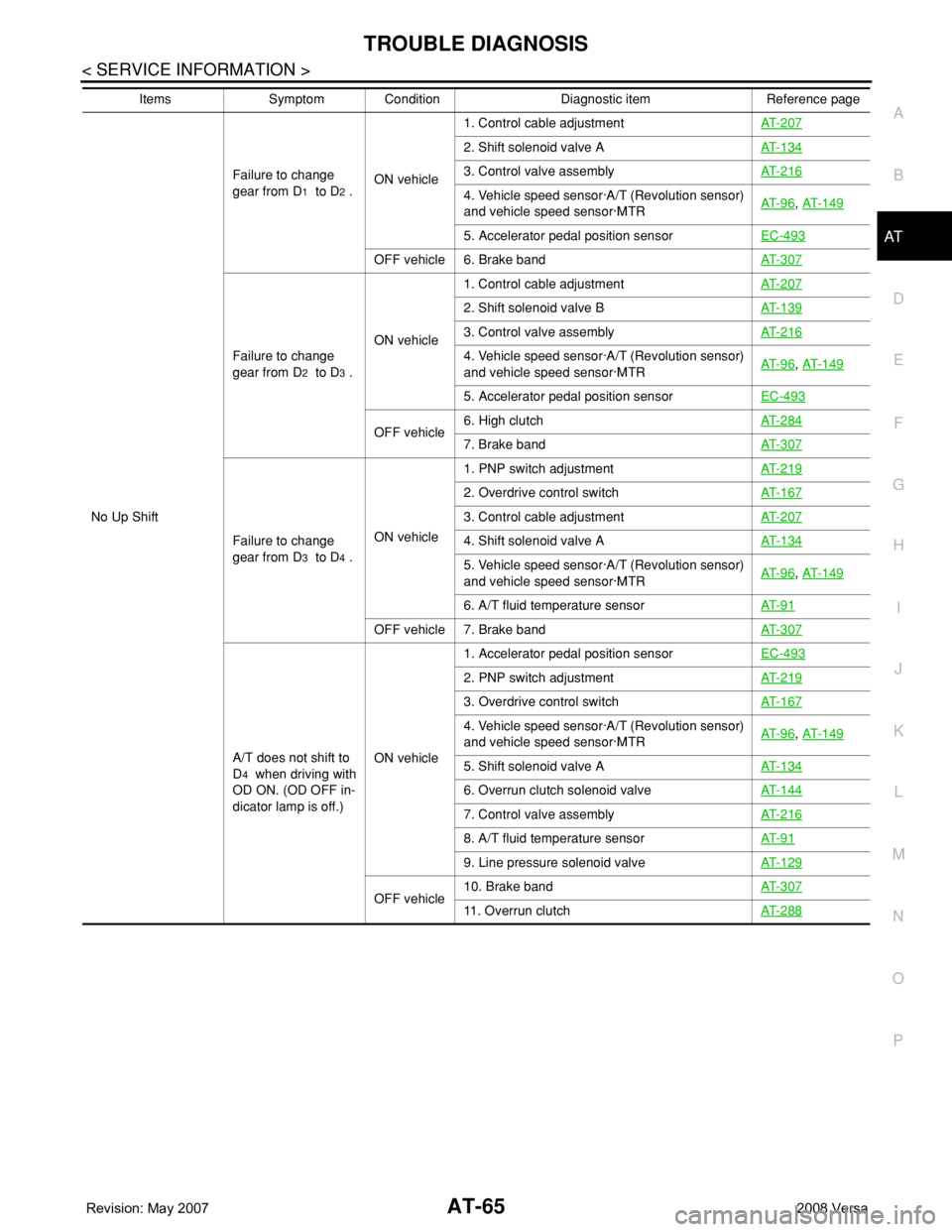
TROUBLE DIAGNOSIS
AT-65
< SERVICE INFORMATION >
D
E
F
G
H
I
J
K
L
MA
B
AT
N
O
P
No Up ShiftFailure to change
gear from D
1 to D2 .ON vehicle1. Control cable adjustmentAT- 2 0 7
2. Shift solenoid valve AAT- 1 3 4
3. Control valve assemblyAT- 2 1 6
4. Vehicle speed sensor·A/T (Revolution sensor)
and vehicle speed sensor·MTRAT- 9 6, AT- 1 4 9
5. Accelerator pedal position sensorEC-493
OFF vehicle 6. Brake bandAT- 3 0 7
Failure to change
gear from D
2 to D3 .ON vehicle1. Control cable adjustmentAT- 2 0 7
2. Shift solenoid valve BAT- 1 3 9
3. Control valve assemblyAT- 2 1 6
4. Vehicle speed sensor·A/T (Revolution sensor)
and vehicle speed sensor·MTRAT- 9 6, AT- 1 4 9
5. Accelerator pedal position sensorEC-493
OFF vehicle6. High clutchAT- 2 8 47. Brake bandAT- 3 0 7
Failure to change
gear from D
3 to D4 .ON vehicle 1. PNP switch adjustmentAT- 2 1 9
2. Overdrive control switchAT- 1 6 7
3. Control cable adjustmentAT- 2 0 7
4. Shift solenoid valve AAT- 1 3 4
5. Vehicle speed sensor·A/T (Revolution sensor)
and vehicle speed sensor·MTRAT- 9 6, AT- 1 4 9
6. A/T fluid temperature sensorAT- 9 1
OFF vehicle 7. Brake band AT- 3 0 7
A/T does not shift to
D
4 when driving with
OD ON. (OD OFF in-
dicator lamp is off.)ON vehicle1. Accelerator pedal position sensorEC-493
2. PNP switch adjustmentAT- 2 1 9
3. Overdrive control switchAT- 1 6 7
4. Vehicle speed sensor·A/T (Revolution sensor)
and vehicle speed sensor·MTRAT- 9 6, AT- 1 4 9
5. Shift solenoid valve AAT- 1 3 4
6. Overrun clutch solenoid valveAT- 1 4 4
7. Control valve assemblyAT- 2 1 6
8. A/T fluid temperature sensorAT- 9 1
9. Line pressure solenoid valveAT- 1 2 9
OFF vehicle10. Brake bandAT- 3 0 711. Overrun clutchAT- 2 8 8
Items Symptom Condition Diagnostic item Reference page
Page 78 of 2771

AT-66
< SERVICE INFORMATION >
TROUBLE DIAGNOSIS
Slips/Will Not EngageVehicle will not run in
“R” position (but runs
in “D”, “2” and “1” po-
sitions). Clutch slips.
Very poor accelera-
tion.ON vehicle1. Control cable adjustmentAT- 2 0 7
2. Stall testAT- 4 8
3. Line pressure testAT- 4 8
4. Line pressure solenoid valveAT- 1 2 9
5. Control valve assemblyAT- 2 1 6
OFF vehicle6. Reverse clutchAT- 2 7 9
7. High clutchAT- 2 8 4
8. Forward clutchAT- 2 8 8
9. Overrun clutchAT- 2 8 8
10. Low & reverse brakeAT- 2 9 5
Vehicle will not run in
“D” and “2” positions
(but runs in “1” and
“R” positions).ON vehicle 1. Control cable adjustmentAT- 2 0 7
OFF vehicle 2. Low one-way clutchAT- 2 4 0
Vehicle will not run in
“D”, “1”, “2” positions
(but runs in R posi-
tion). Clutch slips.
Very poor accelera-
tion.ON vehicle1. A/T fluid levelMA-22
2. Stall testAT- 4 8
3. Line pressure testAT- 4 8
4. Line pressure solenoid valveAT- 1 2 9
5. Control valve assemblyAT- 2 1 6
6. Accumulator N-DAT- 2 1 6
OFF vehicle7. Reverse clutchAT- 2 7 9
8. High clutchAT- 2 8 4
9. Forward clutchAT- 2 8 8
10. Forward one-way clutchAT- 2 9 9
11. Low one-way clutchAT- 2 4 0
Clutches or brakes
slip somewhat in start-
ing.ON vehicle1. A/T fluid levelMA-22
2. Control cable adjustmentAT- 2 0 7
3. Accelerator pedal position sensorEC-493
4. Line pressure testAT- 4 8
5. Line pressure solenoid valveAT- 1 2 9
6. Control valve assemblyAT- 2 1 6
7. Accumulator N-DAT- 2 1 6
OFF vehicle8. Forward clutchAT- 2 8 8
9. Reverse clutchAT- 2 7 9
10. Low & reverse brakeAT- 2 9 5
11 . O i l p u m pAT- 2 6 0
12. Torque converterAT- 2 4 0
Items Symptom Condition Diagnostic item Reference page